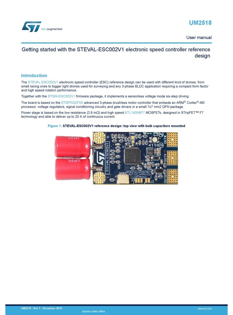
ST UM2520 User manual

Introduction
The STEVAL-IPFC01V1 3 kW interleaved PFC reference design is based on the STNRGPF01 digital controller and includes a
separate power board, control board and programming board. The STNRGPF01 is a digital configurable ASIC developed by
STMicroelectronics, which can drive up to three channels in an interleaved PFC for industrial applications.
The STNRGPF01 digital controller on the control board implements mixed signal (analog/digital) average current mode control
in CCM at fixed frequency. The analog section ensures cycle-by-cycle current regulation, while digital control manages the non-
time critical operations. You can use the eDesignSuite software available on the ST website to configure the STNRGPF01 to
satisfy the specifications of each interleaved PFC.
Figure 1. STEVAL-IPFC01V1 3 kW interleaved PFC reference design
How to use the 3 kW three-channel interleaved PFC based on the STNRGPF01
digital controller
UM2520
User manual
UM2520 - Rev 3 - October 2019
For further information contact your local STMicroelectronics sales office.
www.st.com

1Safety instructions
Danger:
The evaluation board uses voltage levels that can cause serious injury and even death.
Do not touch any of the boards immediately after disconnecting the input power supply as the
charged capacitors need time to discharge.
Due to the high power density, the board components and the heat sink can become very hot and
cause severe burns when touched.
This board is intended for use by skilled technical personnel who are suitably qualified and familiar with the
installation, use and maintenance of power electronic systems. The same personnel must be aware of and must
apply national accident prevention rules.
The electrical installation shall be completed in accordance with the appropriate requirements (e.g., cross-
sectional areas of conductors, fusing, and GND connections).
UM2520
Safety instructions
UM2520 - Rev 3 page 2/28

2STEVAL-IPFC01V1 evaluation kit overview
Figure 2. STEVAL-IPFC01V1 block diagram
1. I/O measurement signals
2. Analog circuitry
3. Power stage
4. Digital control section with STNRGPF01 digital controller
EMI filter
&
rectification
3-channel
interleaved
PFC
Driver Driver Driver
Current
compensator
Triangular
wave
generator
Analog
filter
STNRGPF01
SIN_REF PWM0
flip-flop
SET1 RESET1
OUT_PI[2],[3]
TRIANG_REF
CLOCK
VIN
VDD
VSS
IOUT
VOUT
flip-flop
SET2 RESET2
Load
Auxiliary
Power
Supply
AC
input
DC
output
PWM0 PWM1 PWM2
Itot_fb
1
1
1
1
2
22
33
333
3
3
4
4 4
The STEVAL-IPFC01V1 implements mixed signal (analog/digital) control, so the converter can manage a range of
input and output conditions and still remain highly responsive to fast transients in input signals. The inner current
loop is a hardware analog proportional-integral (PI) compensator that ensures the highest possible bandwidth and
cycle-by-cycle sensing and regulation. The outer voltage loop is performed by a digital PI controller with fast
dynamic response.
2.1 Features
• Input voltage range: 90 to 265 VAC
• Line frequency range: 47 to 63 Hz
• Maximum output power: 3 kW at 230 V
•Output voltage: 400 V
• Power factor: > 0.98 at 20% load
• Total Harmonic Distortion: <5% at 20% load
• Mixed-signal average current mode control, CCM fixed frequency operation
• Switching Frequency: 111 kHz
• Cycle-by-cycle regulation (analog current control loop)
• Input voltage and load feed-forwards
• Phase shedding
• Burst-mode operation
• Overvoltage protection
• Thermal protection
• Status indicator LEDs
• Inrush current limiter function
• Cooling function
UM2520
STEVAL-IPFC01V1 overview
UM2520 - Rev 3 page 3/28

3How to use the STEVAL-IPFC01V1 evaluation board
To perform functional and efficiency testing, you need the following equipment:
•Programmable AC source with power > 3 kW
•DC electronic load/or load resistor > 3 kW
•Power analyzer
• Digital oscilloscope
The STEVAL-IPFC01V1 board can be tested at up to 3 kW at 230 VRMS and 1.5 kW at 115 VRMS, in a frequency
range between 47 and 63 Hz.
Note: Any load or passive oscilloscope probe must be isolated from the input source for the PFC.
3.1 How to connect and start the STEVAL-IPFC01P1 power board
Step 1. Insert the STEVAL-IPFC01C1 control board in connector J301 on the STEVAL-IPFC01P1 power board.
Figure 3. STEVAL-IPFC01C1 insertion in STEVAL-IPFC01P1 J301 connector
J301
Step 2. Connect a 230 V/50 Hz or 115 V/60 Hz AC source to the J2 connector on the STEVAL-IPFC01P1
power board.
Figure 4. STEVAL-IPFC01V1 AC source connection
GND
AC IN
UM2520
How to use the STEVAL-IPFC01V1 evaluation board
UM2520 - Rev 3 page 4/28

Step 3. Connect the load wires to the J1 output terminals on the STEVAL-IPFC01P1 power board.
The actual load (electronic dc load, load resistors, inverter, etc.) must remain disconnected until the
soft startup sequence has completed.
The correct polarity is indicated on the board.
Figure 5. STEVAL- IPFC01V1 DC output connection
GND
+400V
Step 4. Supply one of the following input voltage and frequency ranges while no load is connected on the
output:
– 185 – 265 VAC at 47 - 53 Hz
– 90 – 140 VAC at 57 – 63 Hz
Step 5. Wait for the green LED D2 on the STEVAL-IPFC01C1 control board to light up.
The LED indicates that the startup sequence has finished.
Step 6. Connect the load.
Do not connect the load before the green LED indicates that the board is ready or you may damage the
board.
3.1.1 STEVAL-IPFC01P1 power board startup sequence
1. The appropriate AC input voltage is applied under a no load condition.
–185 – 265 VAC at 47 - 53 Hz
– 90 – 140 VAC at 57 – 63 Hz)
2. When the input voltage rises above 60 V, the auxiliary power supply starts and generates the auxiliary
voltages (15 VDC and 5 VDC) for the drivers and the signal conditioning circuitry.
3. Once the auxiliary voltages are nominal, the inrush current limiter phase begins by charging the output
capacitor until the DC voltage reaches the peak input voltage. The charge current is limited by resistor R101.
UM2520
How to connect and start the STEVAL-IPFC01P1 power board
UM2520 - Rev 3 page 5/28

Figure 6. STEVAL-IPFC01V1 DC input connection
1nF
0
100 nF
R112
AC-IN-L1
VIN
1
3
47k
4
L100
AC-IN-L2
2.2nF
R104
470k
250Vac-16A
2
F100
N.M.
R102
-+
3
33k - 1206
D103
20A
470k
GF1M
A1
33k - 1206
R113
VDD
N.M.S14K275
R109
2
ZVD
R105
3
1
2
3
C102
R108
R111
D104
R106
GF1M
A
100nF
V_INPUT
33k
15V
1
2
2
5
TLP385
50A
A2
2.2nF
D102
Y100
R114
150
D101
1
3k 0.1%
C100
C101
R101
1
10M
10M
7
8
RV100
3
RL100
3
VIN
2x 4.5 mH
2
Y101
Q100
D100
GF1M
6
0
14
STS6NF20V
ISO100
4
11
470k
STPS1L30A
J100
1
1
100k - 1206
R110
4
RELAY
12
2
4
R100 22
33k - 1206
R103
470k
R107
1. The STNRGPF01 then checks for any output current flow:
–If there is no current, the STNRGPF01 closes the contacts of a mechanical relay in parallel with
resistor R101.
–If any current is detected, the STNRGPF01 will keep the relay contacts on R101 open (so the board
cannot start) until the current falls to zero.
2. After the inrush limiter phase, the soft startup is activated and the output voltage rises up to 436 VDC, at
which point the PFC enters burst mode to regulate the output voltage between 416 and 436 VDC.
3. The green LED D2 on the control board indicates that the sequence has finished and the PFC is ready for
the load to be connected:
– the output voltage is regulated to 400 V ±2 V.
– for 185 – 265 V 50 Hz mains, the maximum output power is 3000 W
– for 90 – 140 V 60 Hz mains, the maximum output power is 1500 W
Warning:
If the load is connected before the Inrush current limiter phase, a very high current will flow into
the PFC and possibly damage the board when the relay closes the contacts across resistor R101.
UM2520
How to connect and start the STEVAL-IPFC01P1 power board
UM2520 - Rev 3 page 6/28

4PFC controller customization with eDesign Suite
The eDesignSuite suite software tool developed by STMicroelectronics helps you configure ST products power
conversion applications. You can use it to customize the PFC controller for a specific application: you start by
entering the main specifications for your design and then generate an automatic design or follow a sequential
process to build a highly customized design.
Figure 7. PFC specifications
UM2520
PFC controller customization with eDesign Suite
UM2520 - Rev 3 page 7/28

5Status LEDs and fault conditions
The STEVAL-IPFC01C1 control board has a green LED and a red LED connected to STNRGPF01 pin 15
(PFC_OK) and pin 14 (PFC_FAULT), respectively.
5.1 Normal operation
During normal operation, the green LED (D1) on the STEVAL-IPFC01C1 control board remains lit to indicate that
the PFC is operating under allowable conditions.
5.2 Fault conditions
When a fault is detected, the red LED (D2) on the STEVAL-IPFC01C1 control board is lit and the green LED (D1)
is switched off. The device stops all switching activities and turns off the fan.
After a fault condition, the board must be reset by switching off the AC input voltage and discharging the output
capacitors.
Warning:
Do not short the output terminals to discharge the capacitors as the high discharge current may
damage the output current sensing circuitry.
The following conditions will trigger fault protection:
• Frequency or voltage out of range or highly irregular input voltage waveforms that inhibit frequency
measurement. For example, if the input voltage is 230 Vrms but the mains frequency is 60 Hz, or if the input
voltage is 115 Vrms and the mains frequency is 50 Hz.
• Overcurrent condition on at least one PFC channel. This protection prevents PFC inductor saturation.
• Overvoltage protection on output voltage if the output voltage exceeds 450 VDC
• Overvoltage protection on input voltage:
– for 115 V nominal supply: above 140 V
– for 230 V nominal supply: above 265 V
• Over-temperature protection when the ambient temperature of the board exceeds the threshold setting.
5.3 Wait conditions
The following conditions are signaled when both the green LED (D1) and the red LED (D2) on the STEVAL-
IPFC01C1 control board switched off:
• Undervoltage condition on the output when the DC bus voltage falls below 340 V.
•Undervoltage condition on input when the input rms voltage falls below 90 V at 60 Hz or 185 V at 50 Hz.
• Input voltage dropout when the input voltage signal disappears for more than 25 ms.
Under these conditions, the STNRGPF01 will drive both LEDs on the control board off and will wait until the
conditions have cleared before repeating the startup sequence.
UM2520
Status LEDs and fault conditions
UM2520 - Rev 3 page 9/28
6STEVAL-IPFC01P1 power board schematics
Figure 9. STEVAL-IPFC01P1 schematic - input section
1nF
0
100 nF
R112
AC-IN-L1
VIN
1
3
47k
4
L100
AC-IN-L2
2.2nF
R104
470k
250Vac-16A
2
F100
N.M.
R102
-+
3
33k - 1206
D103
20A
470k
GF1M
A1
33k - 1206
R113
VDD
N.M.S14K275
R109
2
ZVD
R105
3
1
2
3
C102
R108
R111
D104
R106
GF1M
A
100nF
V_INPUT
33k
15V
1
2
2
5
TLP385
50A
A2
2.2nF
D102
Y100
R114
150
D101
1
3k 0.1%
C100
C101
R101
1
10M
10M
7
8
RV100
3
RL100
3
VIN
2x 4.5 mH
2
Y101
Q100
D100
GF1M
6
0
14
STS6NF20V
ISO100
4
11
470k
STPS1L30A
J100
1
1
100k - 1206
R110
4
RELAY
12
2
4
R100 22
33k - 1206
R103
470k
R107
UM2520 - Rev 3 page 10/28
UM2520
STEVAL-IPFC01P1 power board schematics

Figure 10. STEVAL-IPFC01P1 schematic - auxiliary power supply
14
DRAIN2 13
3
4
7COMP
C207
1
3.3k
C200
SRC2
C206
7GND4
R206
L4931ABD50-TR
2
GND1
1
VOUT
33k
8
7
R208 4.7nF
R205
+400V
NC 4
SM6T220A
C210
INHIBIT
6GND3 GND2
L2004.7µH
R207
C204
12k
D201 STPS2150A
D200
4GND
TMMBAT46
C209
C201
24k
100
C208
1nF
+
+
470µF
24k
470µF
470nF
VDD
+
L201
ALTAIR05T-800
C203
15V
C205
3
470µF
U200
4.7µF
U201
D204
6
15
DRAIN3
SRC1
2
2.2mH
6V
DRAIN4
5IREF
5
10
VIN
8
D202
VDD 3
470nF
5
2.7
470nF
4.7µF
16
DRAIN1
1
C202
STTH1L06A
R203
R202
+
FB
6
R204
2.7
D203 STPS1L30A
10µF
R200
UM2520 - Rev 3 page 11/28
UM2520
STEVAL-IPFC01P1 power board schematics

Figure 11. STEVAL-IPFC01P1 schematic - boost interleaving section
C310
STW 40N60M2
2
STPS1L30A
OCP_EN
D313
37
PW M0
31
R302
C339
R365
D319
1nF
2
R316 10
U301
17
-
+
9
R311
CS2
OUT1
8
EN2
2.2k 0.1%
R320
15V
5
VDD
4.7k
10m
+
Vcc 6
CS1
3
CON40A
I_LOAD
A
J300
2.2k 0.1%
C324
OUT1
EN2 8
5
OUT2
62k 0.1%
U307
PW M1
100nF
R345
470k
3
470k
100pF
TS3011ILT
R361
VBUS
100pF
L300INDUCTOR
U302
-
+
VDD
9
1
-
+
35
28
FAN2
I_0
1
15V
1
100nF
I_2
10k
PW M2
C307
2.2k 0.1%
D316
U308
21
4
PW M0
L301INDUCTOR
STS6NF20V
6
5
D314
I_in
OCP1
10m
GND
2
1uF
PW M2
6.8k
R353 6.8k
R307
82k 0.1%
5
4
10nF
STPSC12065
D304
TSV911ILT
14
8
2.2k 0.1%
STLM20W 87F
2k
100nF
0
2PWM1
STPS1L30A
R362
10k 0.1%
R308
5
STPS1L30A
D310
100nF
R309
C304
62k 0.1%
1k
R369
470uF
1
STPS1L30A
100nF
R325
R339
V_INPUT
I_in
R315 10
R305
VBUS
30m
C326
100nF
23
R317 10
-
+
U305
+ COMP MMBT6429LT1G
33
10k
C308
10nF
10
100pF
R351
GND2
VDD
STPS1L30A
R340
VDD
38
30
Q302
C319
I_1
3
100nF
100pF
15V
62k 0.1%
R330
C317
18
19
40
R367 100
C313
R333
Q304
4
D301
R357 470
10k
PWM2 5
OUT2
39
R335
10k
5
C300
R314 33
C329
4
2
+
15
R356
10k
FAN
3.3k 0.1%
R331
2
D318
D306
47k
D312
2
STW 40N60M2
15V
0
CS0
11k
510
5
27
VDD
36
100nF
I_1
BAT46JFILM
Y300
C336
OCP1
ZVD
5
4
Q301
VDD
R338
2
C331
VDD
2
100pF
R312
2.2k 0.1%
D302
STPS1L30A
D300
-
+
1
STPS1L30A
R303
VBUS
10
R360 22
62k 0.1%
R358
C301
1
0.56uF
R346
1
1
7
20
33R313
NC
1
33k
GND
3
R336
22
R355
2.2k 0.1%
R328
PWM1
10nF
J301
2.2k 0.1%
C306
RELAY
STPS1L30A
R344
2.2k 0.1%
R318
R341
100nF
R332
10nF
I_LOAD
OUT2
Vcc 6
2
R300
C322
1EN1
R334
10m
C311
D311
0
Q303
FAN
R366
A
C318
4PWM2
VIN
R343
33
100pF
I_0
150pF
+
C302
TSV911ILT
2
D309
3
470uF
C328
R350
3
6
Vcc
510
3
100
TEMP
VOUT VCC
4
150pF
R323
4m
12
7
8
STPS1L30A
4PWM2
C335
62k 0.1%
C334
4
TSV911ILT
16
62k 0.1%
R337
PM8834
OCP1
100pF
R310
3
R370
470k
R348
2.2k 0.1%
R329
STPSC12065
D305
VDD
100
150pF
RELAY TEMP
3
C340
R363
10nF
1k
C333
U304
26
I_2
+ COMP
STW 40N60M2
R304
2
+ COMP
L302INDUCTOR
C337
100
VOUT
1
3
OCP_EN
2.2k 0.1%
R321
VDD
C305
32
4
TSV911ILT
100
PWM2
A
470uF
9
R359
2
10nF
R354 330k
15V
+
C320
10k 0.1%
5
100nF
U309
4
VDD
10
OUT1
EN2 8
CS1
U306
D317 STPS1L30A
1k
4
STPS1L30A
R326
2
TSV911ILT
I_LOAD
0
7
10nF
-
+
U303
3
FAN
15V
1
R364
2
7EN1
1
C309
PM8834 PM8834
R319
100
VDD
3.3nF
STPS1L30A
R342
VDD
C323
4
STPSC12065
D315
C303
470uF
D308
4
2
OCP_EN
100
29
C316
100nF
4
Q300
C332
1
C338
PWM1
GND
3
C330
10 9
CS2
6
TEMP
5
R306
7
OCP_EN
3
CS0
D303
510
11
STPS1L30A
PWM1
GND
3
U300
R349 3.3k
R347
STPS1L30A
R327
C312
13
EN1
1
100
STPS1L30A
D307
1
VDD
I_in
R324
82k 0.1%
R301
ZVD
15V
100
100
STPS1L30A
C325
10nF
R368
100
1nF
1
2
25
PWM0
C327
R322
3
+400V
R352
+ COMP
5
PW M0
VIN
34
24
UM2520 - Rev 3 page 12/28
UM2520
STEVAL-IPFC01P1 power board schematics

7STEVAL-IPFC01C1 control board schematic
Figure 12. STEVAL-IPFC01C1 schematic
C12
10k 0.1%
PWM1
8
I_LOAD
VIN
C31
R17
34
26
29
VDD
R19
20
100nF
23
R242.4k
11
R26
U4
C1
SET2
+
SET2
19
VDD
RED LED
PWM2
VOUT
VDD
RELAY
C6
35
22
2.2nF
R37
33
VDD
2
10k
VDD
U2D
VDDA
RESET2
RESn
N.M.
VDD
R23
N.M.
PWM0
PWM0
C32
1
RED LED
SET1 R6
PFC_OK
CCO_clk
15nF
C38
R9
74HC132
VDD
100nF
22k
FAN
2
I_in1
8
SET1
1µF
REF SIN
ENABLE
R18
7
5
C13
3
VDD
14
C37
11
RED
PWM[0]
FAN
7
13
C28
O+in
U1
16
7
100pF
25
47µF
VDD
OUT_PI[2]
10
C10
150pF
5
ZVD
10k
C27
OUT_PI
REF SIN
14
RTX_RX
VDD
SWIM
VDD
O-in
100nF
1
PIN29
3
4
VDD
10k
R14
WE-CBF
21
TSV911ILT 10k
10k
VSSA
12
RESET2
PTX
3
2
VCOUT
SYNCR[1] 6
OCP1
74HC132
10nF
100nF
I_in2
VDD
22k
C33
FAN
VBUS
4
R38 100k
21
36
20
OUT_PI[3]
11
25
A
14
R27
100
31
CON4
U2C
VIN
VDD
CCO_clk
1.5nF
PWM1
1
12
C34
56k
+
R10
TRIANG REF
TEMP
PTX_TX
26
100pF
RESET1
14 PFC_FAULT
OCP
N.M.
VIN
OCP1
n.c.
C11
14
C30
150pF
10nF
100
R21R28
220nF
4
A
TRIANG_REF
A
R31
2
LMV358IDT
4
3
R29 0
3.3k
37
A
6.2k
35
12
R25 220K
30
31
VIN
9
U2B
+
U5A
RESET1
150pF
R8
R16
C16
GREEN LED
VSS
10k
J1
R7
100pF
100
9
VDDA
16 SIN_REF
SET2
C23
1
2
12
4.7µF
10V
C2
15nF
U5B
VDD
7
7
14
C17
8
R11
CLOCK
GREEN LED
RESET2
C4
I_0
D2
C36
27
14
I_1
O+in
100nF
R39 100k
TEMP
C15
100nF
C8
A
3
A
R[1]
R[3]
23
RELAY
VDD
37
PRX
34
7
220nF
100pF
6
10nF
5
TRIANG REF
R35 3.3k
SET1
OCP[0]
2
9
10
6
R15
1
2
OCP1
74HC132
U2A
C29 100pF
R12
220nF
15
1k
38
100nF
A
10
74HC132
VDD
A
-
I_LOAD
R33
R[2]
100pF
33pF
56k
14
TEMP
NC[1]
ZVD
32
+
8
I_in1
9
RTX_RX
VDD
1
R22
4
VDD
R40 100k
C7
R30
VDD
R4
74HC132
3
5
10nF
RELAY
C9
2.2k
18
10nF
N.M.
NC[2]
PWM0
74HC132
R2
PWM0
C39
7
FAN
10nF
CCO_clk
-
1k
36
C40
ZVD
D1
0
I_in2
A
28
10k
C3
27
VDD
38
2
74HC132
7
C21
13
39
-
VDD
+
3
4
1nF
100pF
C26
40
GREEN
74HC132
IOUT
10pF
TEMP
I_2
1
24
R36
VDD
10k 0.1%
VDD
8
A
8
NRST
J3
A
13
I_2
7.5k
6
C24
C14
OCP[1] 28
13
5.1k
C19
32
PTX_TX
7
100
R34
330pF
CON40A
OUT_PI
17
4
PWM0
22
220nF
U3B
3
4
33pF
30
U3C
A
5
R1
R[4]
10
U3D
STNRGPF01
U3A
R32
ZVD
14
VBUS
6
R20
I_1
11
L1
C5
15
100nF
18
C35
I_LOAD
RELAY
7
J2
4
LMV358IDT
33
14
C22
29
C18
PWM2
R13
15k
19
C25
7
PWM2
VBUS
17
24
C20
I_0
PROGRAMMING PORT
SYNCR[2]
RESET1
1
5
UM2520 - Rev 3 page 13/28
UM2520
STEVAL-IPFC01C1 control board schematic

8STEVAL-IPFC01A1 adapter board schematic
Figure 13. STEVAL-IPFC01A1 schematic
J
2
YELLOW
R403
1k
LED
1
RED
YELLOW
401
Q400
470k
J400
RED
R401 330
4
3
2
1
BLACK
MMBT2222ALT1G
R402
1
2
3
4
5
6
8
7
6
5
D400
CON4
CON6
GREEN
BROWN
3
ORANGE
ORANGE
UM2520 - Rev 3 page 14/28
UM2520
STEVAL-IPFC01A1 adapter board schematic

9STEVAL-IPFC01V1 3 kW interleaved PFC bill of materials
Table 1. STEVAL-IPFC01V1 bill of materials
Item Q.ty Ref. Part / Value Description Manufacturer Order code
1 1 - STEVAL-
IPFC01P1 Power board ST not available separately
2 1 - STEVAL-
IPFC01C1 Control board ST not available separately
3 1 - STEVAL-
IPFC01A1 adapter board ST not available separately
9.1 STEVAL-IPFC01P1 power board bill of materials
Table 2. STEVAL-IPFC01P1 bill of materials
Item Q.ty Ref. Part / Value Description Manufacturer Order code
1 1 C100 100nF, 275Vac,
±20%
POLYPROPILENE
FILM CAP, through
hole lead spacing
15mm
PANASONIC ECQUAAF104MA
2 1 C101 100nF, 50V,
±10% 0603 ANY ANY
3 1 C102 1nF, 500Vdc,
±20%
Ceramic disc cap,
through hole lead
spacing 7.5mm
VISHAY BC
COMPONENTS VY1102M35Y5UG63V0
4 3 C200, C204,
C208
470nF, 50V,
±20%
X7R Ceramic
Capacitor, 0805 TDK CGA4J3X7R1H474M125AE
5 3 C201, C202,
C203
470µF, 25V,
±20%
Electrolytic
capacitor +105°, TH
8mm diameter,
3.5mm lead spacing
ANY ANY
6 1 C205 10µF, 25V,
±20%
Electrolytic
capacitor +105°,
through hole lead
spacing 2.5mm
ANY ANY
7 2 C206, C207 4.7µF, 50V,
±10%
Ceramic Capacitor,
1210 MULTICOMP MULTICOMP
8 1 C209 4.7nF, 50V,
±10%
X7R Ceramic
Capacitor, 0603 ANY ANY
9 2 C210, C340 1nF, 50V, ±10% X7R Ceramic
Capacitor, 0603 ANY ANY
10 4 C300, C301,
C302, C303
470µF, 450V,
±20%
Electrolytic
capacitor +105°,
through hole lead
spacing 10mm
Nichicon LGL2W471MELC35
11 1 C304 0.56µF, 450V,
±10%
POLYPROPILENE
FILM CAP
, through
hole lead spacing
22.5mm
EPCOS B32673P6564K000
12 1 C305 1µF, 520V,
±10%
POLYPROPILENE
FILM CAP, through
hole lead spacing
22.5mm
EPCOS B32673Z5105K000
UM2520
Bill of materials
UM2520 - Rev 3 page 15/28

Item Q.ty Ref. Part / Value Description Manufacturer Order code
13 11
C306, C328,
C329, C330,
C334, C307,
C323, C324,
C325, C332,
C339
10nF, 50V,
±10%
X7R Ceramic
Capacitor, 0603 ANY ANY
14 3 C308, C309,
C310
100pF, 630 Vdc,
±5%
POLYPROPILENE
FILM CAP, through
hole lead spacing
5mm
KEMET PFR5101J630J11L4BULK
15 4 C311, C312,
C313, C326
100pF, 50V,
±5%
COG Ceramic
Capacitor, 0603 ANY ANY
16 11
C316, C317,
C319, C322,
C331, C335,
C336, C337,
C338, C318,
C320
100nF, 50V,
±10%
X7R Ceramic
Capacitor, 0603 ANY ANY
17 1 C327 3.3nF, 50V, ±5% C0G Ceramic
Capacitor, 0603 ANY ANY
18 3 C328, C329,
C330
150 pF, 50V,
±5%
C0G Ceramic
Capacitor, 0603 ANY ANY
19 1 C333 1nF, 50V, ±5% C0G Ceramic
Capacitor, 0603 ANY ANY
20 18
D100, D203,
D303, D304,
D305, D306,
D307, D308,
D309, D310,
D311, D312,
D313, D314,
D316, D317,
D318, D319
30V, 1A Power schottky
diode, SMA ST STPS1L30A
21 1 D101 50A, 1000V, 50A Single Phase Bridge
Rectifier, GBJ
HY Electronic
Corp GBJ5010
22 3 D102, D103,
D104
GF1M, 1000V,
1A
General Purpose
Rectifier Diode,
SMA
ON
Semiconductor GF1M
23 1 D200 220V TRANSIL, SMB ST SM6T220A
24 1 D201 150V, 2A Power schottky
diode, SMA ST STPS2150A
25 1 D202 1000V, 1A
Turbo 2 ultrafast
high voltage
rectifier, SMA
ST STTH1L06A
26 1 D204 100V, 150mA
Small signal
Schottky diode,
SMD Minimelf
ST TMMBAT46FILM
27 3 D300, D301,
D302 600V, 12A
Silicon carbide high
voltage rectifier,
TO220AC
ST STPSC12065D
28 1 D315 100V, 150mA
Small signal
Schottky diode,
SOD-323
ST BAT46JFILM
29 1 F100 20A, 250Vac,
20A, 0%
Cylindrical Fuse
Class gG/gL and
aM, SMD 10x3 mm
Bel Fuse Inc. SMM 20
UM2520
Bill of materials
UM2520 - Rev 3 page 16/28

Item Q.ty Ref. Part / Value Description Manufacturer Order code
30 1 ISO100 80V, 50mA , 0% Optocoupler, SMD Toshiba TLP385
31 1 J100 VIN, 630V,
17.5A
PCB terminal block,
through hole lead
spacing 7.5mm
Phoenix Contact 1717033
32 1 J300 VOUT, 300Vac,
25A
PCB terminal block,
through hole lead
spacing 7.62mm
RS Pro 790-1130
33 1 J301 CON40A,
550Vca, 6.9A
PCB terminal block
female, through hole
lead spacing 2.54
mm
Samtec ESQ12037GD
34 1 L100
2x 4.5 mH,
250V, 18A,
±20%
Common Mode
Power Line Choke,
through hole
WURTH
ELEKTRONIK 7448051804
35 1 L200 4.7uH, 1.7A,
±20%
SMD Inductor, SMD
4.5x4mm
NIC
COMPONENTS NPI43C4R7MTRF
36 1 L201 2.2mH, 0.47A,
±10%
Switch Mode
Transformer,
through hole
AQ Magnetica
OR
Würth Elektronik
2198.0037
OR
750 318 675
37 3L300, L301,
L302 ±10% Power inductor,
through hole PQ32
AQ Magnetica
OR
Würth Elektronik
2083.0011
OR
750316867
38 2 Q100, Q304 18V, 1A
N-channel 20 V,
Power MOSFET,
SO8
ST STS6NF20V
39 3 Q300, Q301,
Q302 600V, 40A MDmesh II Plus™
low Qg, TO-247 ST STW40N60M2
40 1 Q303 45V, 200 mA
BJT NPN small
signal transistor,
SOT-23
ON
Semiconductor MMBT6429LT1G
41 1 RL100 250Vac-16A,
250V, 16A, 0%
RELAY SPST,
through hole
SCHRACK - TE
CONNECTIVITY RT314018
42 1 RV100 S14K275,
275Vac, ±10%
METAL OXIDE
VARISTORS,
through hole lead
spacing 6mm
EPCOS B72214S0271K101
43 2 R100, R360 22, 200V, ±1% Metal film resistor,
1206 ANY ANY
44 1 R101 150, 350V, ±5%
High power ceramic
resistors, through
hole
TE Connectivity SQMW5150RJ
45 4 R102, R203,
R362 33k, 50V, ±1% Metal film resistor,
0603 ANY ANY
46 7
R103, R104,
R112, R113,
R301, R304,
R308
470k, 200V,
±1%
Metal film resistor,
1206 ANY ANY
47 3 R105, R108,
R109 33k, 200V, ±1% Metal film resistor,
1206 ANY ANY
48 1 R106 100k, 200V,
±1%
Metal film resistor,
1206 ANY ANY
UM2520
Bill of materials
UM2520 - Rev 3 page 17/28

Item Q.ty Ref. Part / Value Description Manufacturer Order code
49 2 R107, R111 10M, 50V, ±1% Metal film resistor,
0603 ANY ANY
50 1 R110 47k, 50V, ±1% Metal film resistor,
0603 ANY ANY
51 1 R114 3k ±0.1%, 50V,
0%
Metal film resistor,
0603 ANY ANY
52 1 R200 3.3k, 200V, ±1% Metal film resistor,
1206 ANY ANY
53 1 R202 100, 200V, ±1% Metal film resistor,
1206 ANY ANY
54 1 R204 12k, 50V, ±1% Metal film resistor,
0603 ANY ANY
55 1 R205 24k, 50V, ±1% Metal film resistor,
0603 ANY ANY
56 2 R206, R207 2.7, 200V, ±1%
Professional MELF
Resistors, MELF
0204
Vishay MMA02040C2708FB300
57 1 R208 24k, 50V, ±1% Metal film resistor,
0603 ANY ANY
58 1 R300 30m, ±1%
Ultra Precision
Current Sensing
Chip Resistor, SMD
4527
Stackpole
Electronics Inc. CSS4527FT30L0
59 11
R302, R303,
R332, R334,
R336, R339,
R341, R343,
R351, R352,
R367
100, 50V, ±1% Metal film resistor,
0603 ANY ANY
60 3 R305, R306,
R307 510, 50V, ±1% Metal film resistor,
0603 ANY ANY
61 10
R309, R310,
R333, R335,
R337, R340,
R342, R344,
R356, R358
2.2k ±0.1%,
75V, 0%
Metal film resistor,
0603 ANY ANY
62 2 R311, R325 10k ±0.1%, 50V,
0%
Metal film resistor,
0603 ANY ANY
63 3 R312, R313,
R314 33, 200V, ±1% High Power Thick
Film Resistor, 1206 ANY ANY
64 2 R315, R316 10, 200V, ±1% High Power Thick
Film Resistor, 1206 ANY ANY
65 1 R317 10, 200V, ±1% High Power Thick
Film Resistor, 1206 ANY ANY
65 3 R318, R322,
R320 10k, 200V, ±1% High Power Thick
Film Resistor, 1206 ANY ANY
67 3 R319, R321,
R323 10m, ±1%
Wirewound Res.,
Precision, SMD
2512
OHMITE MCS3264R010FER
68 1 R324 3.3k ±0.1%,
75V, 0%
Metal film resistor,
0603 ANY ANY
69 1 R326 4m, ±1% Metal film resistor,
SMD 3921 Vishay WSLP39214L000FEA
UM2520
Bill of materials
UM2520 - Rev 3 page 18/28

Item Q.ty Ref. Part / Value Description Manufacturer Order code
70 6
R327, R328,
R329, R346,
R347, R348
62k ±0.1%, 75V,
0%
Metal film resistor,
0603 ANY ANY
71 2 R330, R353 6.8k, 50V, ±1% Metal film resistor,
0603 ANY ANY
72 1 R331 2k, 50V, ±1% Metal film resistor,
0603 ANY ANY
73 1 R338 4.7k, 50V, ±1% Metal film resistor,
0603 ANY ANY
74 1 R345 47k, 50V, ±1% Metal film resistor,
0603 ANY ANY
75 1 R349 3.3k, 50V, ±1% Metal film resistor,
0603 ANY ANY
76 1 R350 10k, 50V, ±1% Metal film resistor,
0603 ANY ANY
77 1 R354 330k, 50V, ±1% Metal film resistor,
0603 ANY ANY
78 2 R355, R359 82k ±0.1%, 75V,
0%
Metal film resistor,
0603 ANY ANY
79 1 R357 470, 50V, ±1% Metal film resistor,
0603 ANY ANY
80 1 R361 11k, 50V, ±1% Metal film resistor,
0603 ANY ANY
81 1 R363 10k, 50V, ±1% Metal film resistor,
0603 ANY ANY
82 3 R364, R365,
R366 0, 200V, ±1% Metal film resistor,
1206 ANY ANY
83 3 R368, R369,
R370 1k, 50V, ±1% Metal film resistor,
0603 ANY ANY
84 1 U200 5V, 0.25A
Very low drop
voltage regulators
with inhibit, SO8
ST L4931ABD50, TR
85 1 U201 900V
Off-line all-primary-
sensing switching
regulator, SO16N
ST ALTAIR05T, 800
86 5
U300, U301,
U302, U303,
U305
-
rail to rail input/
output 5V CMOS
Op-Amp, SOT23-5L
ST TSV911ILT
87 1 U304 -
Rail-to-rail high-
speed comparator,
SOT23-5L
ST TS3011ILT
88 1 U306 5V
Ultra-low current 2.4
V precision analog
temperature sensor,
SOT323-5L
ST STLM20W87F
89 3 U307, U308,
U309 18V, 4A
4 A dual low side
MOSFET driver,
SO8
ST PM8834TR
90 2 Y100, Y101 2.2nF, 250V,
±20%
Ceramic disc cap, T
H lead spac. 7.5
mm
MURATA DE2E3KH222MA3B
UM2520
Bill of materials
UM2520 - Rev 3 page 19/28

Item Q.ty Ref. Part / Value Description Manufacturer Order code
91 1 Y300 FAN2, 12V,
0.25A
DC Axial Fan,
through hole
40X40X20
ARX FD1240-A0241D0AL
92 1 HEATSINK -
HEATSINK 220mm,
standard finishing
size length: 220 mm
PADA 8411
93 1 PLEXIGLASS
SPACER -
PLEXIGLASS
SPACER, DIM:
240X40x3mm
ANY ANY
94 6 SPACER - Nylon spacer 10mm
M3 - -
95 6 NUT - Nylon NUT M3 - -
96 3 INSULATOR KIT
1-INSULATOR KIT
TO-220 MULTICOMP MK3306/S
97 3 INSULATOR KIT
2-INSULATOR
TO-247 - -
98 2 Screw M3 - M3 steel screws -
10 mm length - -
99 7 Screw M2.5 - M2.5 steel screws -
20 mm length - -
100 7 NUT - M2.5 STEEL NUT - -
101 7 Plain Washer - M2.5 Steel Plain
Washer - -
9.2 STEVAL-IPFC01C1 control board bill of materials
Table 3. STEVAL-IPFC01C1 bill of materials
Item Q.ty Ref. Part / Value Description Manufacturer Order code
1 1 C1 4.7µF, 0805, 16
V, 10 %
X7R Ceramic
Capacitor ANY ANY
2 2 C2, C5 100nF, 0603, 50
V, 10 %
X7R Ceramic
Capacitor ANY ANY
3 4 C3, C4, C15,
C17
10nF, 0603, 50
V, 10 %
X7R Ceramic
Capacitor ANY ANY
4 1 C6 47µF, 1206, 6.3
V, 20 %
Polarized tantalum
chip capacitor AVX TAJA476K006RNJ
5 1 C7 1µF, 0603, 25 V,
10 %
X7R Ceramic
Capacitor ANY ANY
6 6 C8, C21, C22,
C25, C26, C27
100pF, 0603, 25
V, 10 %
X7R Ceramic
Capacitor ANY ANY
7 3 C9, C19, C20 150pF, 0603, 25
V, 5 %
C0G Ceramic
Capacitor ANY ANY
8 2 C10, C37 33pF, 0603, 50
V, 5 %
C0G Ceramic
Capacitor ANY ANY
9 1 C11 100nF, 0603, 50
V, 10 %
X7R Ceramic
Capacitor ANY ANY
10 1 C12 15nF, 0603, 50
V, 10 %
X7R Ceramic
Capacitor ANY ANY
11 4C13, C38, C39,
C40
220nF, 0603, 50
V, 10 %
X7R Ceramic
Capacitor ANY ANY
UM2520
Bill of materials
UM2520 - Rev 3 page 20/28
Table of contents
Other ST Controllers manuals
Popular Controllers manuals by other brands

IPAS
IPAS Power Block Series Operating and mounting instructions

Dettson
Dettson EVO Installation and owner's manual

LRP
LRP SPX Competition StockSpec 80710 user manual

Inverter
Inverter DF-12 user manual

Mitsubishi Electric
Mitsubishi Electric MELSERVO J5 Series user manual

Kapego LED
Kapego LED 843022 manual