ST Turbo+ mPSD DK3400 User manual

March 2007 Rev 3 1/24
UM0299
User manual
Turbo+ µPSD DK3400 with RIDE software
Introduction
The Turbo+ µPSD DK3400 with RIDE software is a development kit which provides all you
need to develop and debug applications. An easy-to-use graphical interface provides a quick
and efficient way of:
■Compiling projects and programming the flash memory, see Section 3.2 on page 9.
■Doing single-step execution and source-level debugging, see Section 3.3 on page 10.
■Obtaining device specific formatted displays, see Section 3.4 on page 10.
■Inserting breakpoints, see Section 3.5 on page 11.
■Performing symbolic debugging and monitoring variables, see Section 3.6 on page 12.
■Iterating code, see Section 3.7 on page 12.
■Setting instruction traces approaching real-time performance, see Section 3.8 on page
13.
This development kit contains a simple demonstration project that illustrates the power and
efficiency of the software development tools based upon Raisonance RIDE software. It also
demonstrates the capabilities of the embedded eRLink which provides many features for
editing, compiling, programming, and debugging programs developed for the Turbo+ µPSD
DK3400 MCU Series from STMicroelectronics.
The demonstration application code is a RIDE-based project that shows how to use the
GPIO block within the µPSD3400 device. It is a very simple demo that drives an external red
LED. During the short tutorial, you will be able to step through the code and change the LED
blinking rate.
The DK3400 kit also includes an evaluation version of Keil µVision 3 and Keil ULINK JTAG
adapter. You can try the evaluation version of µVision 3 (code-limited) and upgrade to a full
version for a complete µPSD3400 development environment.
www.st.com

Contents UM0299
2/24
Contents
1 Delivery checklist . . . . . . . . . . . . . . . . . . . . . . . . . . . . . . . . . . . . . . . . . . . 5
2 Installing the software and connecting the hardware . . . . . . . . . . . . . . 7
2.1 Installing the µPSD3400 development kit CD . . . . . . . . . . . . . . . . . . . . . . . 7
2.2 Connecting the µPSD3400 circuit board . . . . . . . . . . . . . . . . . . . . . . . . . . 7
3 Running the demo project . . . . . . . . . . . . . . . . . . . . . . . . . . . . . . . . . . . . 8
3.1 Opening the demo project in RIDE . . . . . . . . . . . . . . . . . . . . . . . . . . . . . . . 8
3.2 Compiling the project and programming the flash memory . . . . . . . . . . . . 9
3.3 Debugging . . . . . . . . . . . . . . . . . . . . . . . . . . . . . . . . . . . . . . . . . . . . . . . . 10
3.4 Changing the display of information . . . . . . . . . . . . . . . . . . . . . . . . . . . . . 10
3.5 Setting breakpoints in the program . . . . . . . . . . . . . . . . . . . . . . . . . . . . . 11
3.6 Monitoring variables in the Watch window . . . . . . . . . . . . . . . . . . . . . . . . 12
3.7 Iterating code . . . . . . . . . . . . . . . . . . . . . . . . . . . . . . . . . . . . . . . . . . . . . . 12
3.8 Setting instruction traces . . . . . . . . . . . . . . . . . . . . . . . . . . . . . . . . . . . . . 13
3.8.1 Starting the trace utility . . . . . . . . . . . . . . . . . . . . . . . . . . . . . . . . . . . . . 13
3.8.2 Displaying traces . . . . . . . . . . . . . . . . . . . . . . . . . . . . . . . . . . . . . . . . . . 14
3.9 RIDE windows and icons . . . . . . . . . . . . . . . . . . . . . . . . . . . . . . . . . . . . . 16
Appendix A µPSD3400 jumper descriptions and default settings. . . . . . . . . . . 19
Appendix B Product support. . . . . . . . . . . . . . . . . . . . . . . . . . . . . . . . . . . . . . . . . 21
B.1 Software updates . . . . . . . . . . . . . . . . . . . . . . . . . . . . . . . . . . . . . . . . . . . 21
B.2 Hardware spare parts . . . . . . . . . . . . . . . . . . . . . . . . . . . . . . . . . . . . . . . . 21
B.2.1 Sockets. . . . . . . . . . . . . . . . . . . . . . . . . . . . . . . . . . . . . . . . . . . . . . . . . . 21
B.2.2 Connectors . . . . . . . . . . . . . . . . . . . . . . . . . . . . . . . . . . . . . . . . . . . . . . . 21
B.3 Getting prepared before you call. . . . . . . . . . . . . . . . . . . . . . . . . . . . . . . . 22
Appendix C Revision history. . . . . . . . . . . . . . . . . . . . . . . . . . . . . . . . . . . . . . . . . 23
UM0299 List of tables
3/24
List of tables
Table 1. Summary of icons. . . . . . . . . . . . . . . . . . . . . . . . . . . . . . . . . . . . . . . . . . . . . . . . . . . . . . . . 17
Table 2. ED3K4 jumpers factory default settings . . . . . . . . . . . . . . . . . . . . . . . . . . . . . . . . . . . . . . . 19
Table 3. Document revision history . . . . . . . . . . . . . . . . . . . . . . . . . . . . . . . . . . . . . . . . . . . . . . . . . 23
List of figures UM0299
4/24
List of figures
Figure 1. Turbo+ µPSD DK3400 development board . . . . . . . . . . . . . . . . . . . . . . . . . . . . . . . . . . . . . 5
Figure 2. RIDE menu bar. . . . . . . . . . . . . . . . . . . . . . . . . . . . . . . . . . . . . . . . . . . . . . . . . . . . . . . . . . . 8
Figure 3. Project window . . . . . . . . . . . . . . . . . . . . . . . . . . . . . . . . . . . . . . . . . . . . . . . . . . . . . . . . . . . 9
Figure 4. MCU registers. . . . . . . . . . . . . . . . . . . . . . . . . . . . . . . . . . . . . . . . . . . . . . . . . . . . . . . . . . . 11
Figure 5. Watch window. . . . . . . . . . . . . . . . . . . . . . . . . . . . . . . . . . . . . . . . . . . . . . . . . . . . . . . . . . . 12
Figure 6. Trace options . . . . . . . . . . . . . . . . . . . . . . . . . . . . . . . . . . . . . . . . . . . . . . . . . . . . . . . . . . . 14
Figure 7. Code view (disassembly) . . . . . . . . . . . . . . . . . . . . . . . . . . . . . . . . . . . . . . . . . . . . . . . . . . 15
Figure 8. Trace display . . . . . . . . . . . . . . . . . . . . . . . . . . . . . . . . . . . . . . . . . . . . . . . . . . . . . . . . . . . 16
Figure 9. Messages window . . . . . . . . . . . . . . . . . . . . . . . . . . . . . . . . . . . . . . . . . . . . . . . . . . . . . . . 16
Figure 10. RIDE interface window . . . . . . . . . . . . . . . . . . . . . . . . . . . . . . . . . . . . . . . . . . . . . . . . . . . . 18
Figure 11. ED3K4 jumpers factory default settings . . . . . . . . . . . . . . . . . . . . . . . . . . . . . . . . . . . . . . . 20

UM0299 Delivery checklist
5/24
1 Delivery checklist
This section lists the hardware and software components of the Turbo+ µPSD DK3400
development kit.
Hardware components
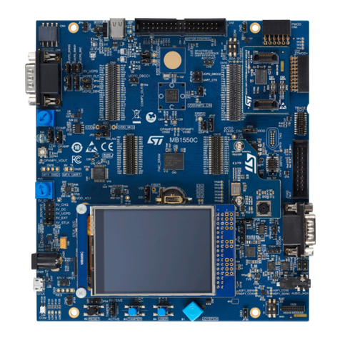
●Turbo+ µPSD DK3400 development board- with a ED3K4 v1.1 daughter-card and
µPSD3434E-40U6 (see Figure 1),
●eRLINK, an embedded JTAG adapter from Raisonance for debugging with Raisonance
integrated development environment (RIDE), present on bottom-side of ED3K4,
●ULINK, a USB-based JTAG adapter from Keil for debugging with Keil's uVision tools,
●USB cables and RS232 cable,
●A 110/220V universal power supply adapter.
Figure 1. Turbo+ µPSD DK3400 development board

Delivery checklist UM0299
6/24
Software components on the Turbo+ µPSD DK3400 CD from
STMicroelectronics
●RIDE C-compiler and assembler (limited to 4Kbytes code size) in RIDE
●RIDE debugger utility (no code size limit) in RIDE
●µPSD3400 sample projects with USB support and application notes
●CAPS software (configuration and programming system) from STMicroelectronics for
configuring the programmable logic inside the µPSD3400. This software is a
replacement for the former PSDSoft Express tool.
●STMicroelectronics datasheets, tools, software, user manual and application notes
●Keil uVision 3 software and support tools for µPSD3400 - (demo version limited to
2Kbytes code size)
The µPSD3400 circuit board with its embedded RLINK tool or your own designed circuit
board with a µPSD3400 MCU is all that is needed to develop code. The RIDE debugger
utility can be used to symbolically debug 8051 code generated from almost any 8051
compiler. Therefore, you have the choice between two options:
●Keeping your existing 8051 compiler and debugging with the RIDE debugger (no code
size limit),
●Upgrading from the evaluation version of the RIDE compiler on the CD to the full
version so that you can compile with no size limit and debug code all within the RIDE
environment. Go to the Raisonance web site for more information on RIDE and
upgrades.

UM0299 Installing the software and connecting the hardware
7/24
2 Installing the software and connecting the hardware
This section explains how to install the software provided on the development kit CD and
how to connect the µPSD3400 circuit board.
2.1 Installing the µPSD3400 development kit CD
1. Insert the STMicroelectronics CD supplied with the µPSD3400 development kit in your
CD drive. The auto run utility will bring up the home page or the main menu page.
2. Click on Install ST and 3rd Party Tools.
3. Install CAPS, accept all default choices.
4. Install RIDE, accept all default choices.
5. Go back to the home page and click on Copy Device Drivers and Demo Code.
6. Click on Install Demos for the Ride Environment (Raisonance).
7. Unzip the files in the foloder of your choice on your hard drive.
2.2 Connecting the µPSD3400 circuit board
1. Check the jumper settings on the board and make sure that they match the default
settings shown in Appendix A: µPSD3400 jumper descriptions and default settings on
page 19.
The embedded Rlink should detect the Turbo+ µPSD DK3400 MCU immediately.
2. Connect the eRLINK USB plug to your PC/laptop using the supplied USB cable and let
the USB driver install on Windows.
3. Attach the power plug (9V DC, 500mA) to the CN0 power jack of the motherboard.
4. Switch ON the DK3400 motherboard (SW1 in position ON).

Running the demo project UM0299
8/24
3 Running the demo project
This section contains a number of exercises that will rapidly help you become familiar with
the major steps for creating and debugging µPSD3400 projects.
Using the demo project supplied with the µPSD3400 development kit as an example, it
provides step-by-step instructions on how to to do basic tasks in RIDE. You can refer to
Figure 10 on page 18 for help as you follow the procedures.
3.1 Opening the demo project in RIDE
1. Launch RIDE from the Windows programs menu (Raisonance Kit 6.1) or from the RIDE
icon.
The RIDE title menu bar is diplayed (see Figure 2) with a blank workspace.
Figure 2. RIDE menu bar
2. Open the demo project.
a) In title menu bar click "Project", then "Open".
b) Double-click on the project named led_blink.prj, in the folder:
\RIDE\EXAMPLES\8051\DERIVATIVES\ST_UPSD\UPSD3400\LED_BLINK
The project files are displayed in the left side of the window. (See Figure 3).
3. Click on the "+" to expand the project files and then double-click on led_blink.c to open
it.

UM0299 Running the demo project
9/24
Figure 3. Project window
3.2 Compiling the project and programming the flash memory
1. Click the "Make All" icon in the menu bar:
This compiles and builds the project.
2. Start the debugger by clicking the debugger icon in the menu bar.
This programs the flash and refreshes the RIDE environment, showing actions in the
"Debug/Action/Messages Window" (See Figure 10 on page 18 ).
The line highlighted in blue in the Code/ Edit/Trace window indicates where MCU
execution has stopped in the main program, waiting for your debugging command. In
the example shown in Figure 10, MCU execution stopped at the first line of executable
code.

Running the demo project UM0299
10/24
3.3 Debugging
1. Click the "Go" icon in the menu bar to run the program.
The program runs full speed with the D6 red LED (middle LED in the bank of 3 red
ones) blinking at a couple HZ frequency.
2. Click the "Reset" icon to restart execution at the first line of the main program.
The blue line should be on blink_delay = SHORT.
3. Click the "Step-In" icon twice.
The debugger is now in the called function, timer0_init().
4. Double click " Disassembly Code" in the left debugger window.
This opens a display named "Disassembly code (led_blink)" showing both C and
Assembly code source instructions.
5. Click the "Step-Over" icon a few times to see that code execution can be stepped one
assembly instruction at a time.
6. Click "Reset" to return to the main program, led_blink.c.
7. Click on the LED_BLINK.C tab the Code/ Edit/Trace window to return to the C code
window.
3.4 Changing the display of information
1. Double-click the "Main Registers" icon in the left debugger window.
The contents of the MCU core registers is displayed (see Figure 4).

UM0299 Running the demo project
11/24
Figure 4. MCU registers
2. Double-click the "Port 1" icon in the left debugger window to show the current value of
the pins in I/O port 1.
3. Go back to the file, led_blink.c by clicking on the tab at the bottom of the main
display window (see Figure 10), and expand the window view back to full screen.
3.5 Setting breakpoints in the program
The µPSD3400 hardware provides physical registers into which up to four hardware
breakpoint addresses can be set by the debugger.
1. Set two breakpoints by clicking on the green dot on the left of the two lines of code
timer0_delay (blink_delay) in the while(1) loop.
The green dot turns into a red S icon and the line of code is highlighted in red as shown
in Figure 10.
2. Click "Go".
The program will run until it hits the first breakpoint.
3. Check the status of the red LED D6.
4. Click "Go" again. See the red LED changing from ON to OFF, toggling back and forth,
by repeatedly clicking on the icon.
5. Remove the two breakpoints, by clicking in the margin on the two red S icons.
6. Click GO again.
The blinking routine now runs without interruption.

Running the demo project UM0299
12/24
3.6 Monitoring variables in the Watch window
1. Click STOP to stop running the program.
2. Double-click the variable name blink_delay at the beginning of the main() function
to highlight it. Right-click on it, then select "Add Watch". Alternatively, press F6.
You can now monitor this variable in the Watch Window at bottom left of the screen as
shown in Figure 5 below and in Figure 10 on page 18.
Figure 5. Watch window
3. Remove any existing breakpoints, then Click "Reset".
4. Click "Go" and then click "Stop" to see that the blink_delay value is updated in the
watch window.
It should report the value 0x0A (see Figure 5).
5. Click "Go" again. While the code is running, place the mouse over the Value field
(should read as 0xA), right-click and select Evaluate, enter 0x64 in the New Value field,
then click on Modify.
The LED should now blink at a rate 10 times slower because the 0x64 value causes a
blink frequency that is 10 times longer than 0xA. This action shows that the debugger is
active while the code is running.
6. Close the Evaluate Expression window. Click "Reset" and then "Go".
The LED is blinking again at the faster rate. Section 3.7 explains how to make this
change permanent in the flash memory.
3.7 Iterating code
You can make the code change described in Section 3.6 permanent in the flash memory, as
explained in the following procedure.

UM0299 Running the demo project
13/24
1. Close the debugger by clicking on the debugger icon. (It is same icon that starts the
debugger).
You are now in the editor.
2. Go to the file led_blink.c by clicking on its file tab, and change the following C code
statement from
blink_delay = SHORT;
to
blink_delay = LONG;
3. Click "Make All" to recompile and rebuild the program.
4. Start the debugger by clicking on the debugger icon to re-program this new code into
the Flash memory.
5. Click "Go" and see that the LED is now permanently blinking at the slower rate.
This code modification is now permanent and resident in the code Flash.
6. Click "Reset".
3.8 Setting instruction traces
The µPSD3400 will rapidly stream a record of all the MCU instruction steps out to the Ride
software via the eRlink adapter. From this data, RIDE creates a formatted file to help you
find even the most stubborn bugs, showing a history as deep as 500,000+ instruction steps
that the MCU has last executed.
3.8.1 Starting the trace utility
1. To enable the trace utility, from the title bar select "Debug", then "Trace", then “Options”.
The trace options dialog box is displayed as shown in Figure 6.
2. Click "Set Trace ON", then click OK.

Running the demo project UM0299
14/24
Figure 6. Trace options
3. To open the Trace Display, from the title bar select "Debug", then "Trace", then "View".
A blank Trace Display window appears.
A Trace Display file can display program source code in both C and Assembly formats.
Tracing runs in the background with little impact on the real-time performance of the
project.
3.8.2 Displaying traces
1. Go back to the file led_blink.c by clicking on its file tab.
2. Set one breakpoint at the following line of code (before while(1)) :
PSD_reg.DATAOUT_D |= LED_OFF; // Initialize LED to OFF
To set the breakpoint, click on the green dot to the left of the line of code. The green dot
turns into a red S and the line is highlighted in red.
3. Click "Go".
The MCU will run until it hits the breakpoint. A window displaying the disassembly code
appears, as shown in Figure 7.

UM0299 Running the demo project
15/24
Figure 7. Code view (disassembly)
Note: The red line indicates where the breakpoint is set, the blue line indicates the next instruction
to execute, and pink lines indicate where a breakpoint happened.
4. Open the Trace Display window by clicking on the "Trace (led_blink)" file tab.
The last instruction that was executed (MCU Program Counter at 01B) is listed at the
bottom of the Trace Display window. Above this line is the history of all the instructions
that the MCU executed before hitting the breakpoint. There should be 13 records. See
Figure 8.

Running the demo project UM0299
16/24
Figure 8. Trace display
5. To list both C and ASM code instructions, right-click in the trace window, select Options,
and in the Trace Options dialog box, select ASM and C sequential list.
6. Go back to the file led_blink.c and click "Go".
The LED should now blink normally and in real-time.
7. After about 10 seconds click "Stop" and look at the messages in the window that
records the actions (see Figure 9).
This window shows the number of non-sequential instructions traced. Thousands of
instructions are now showing in the Trace window.
The powerful Trace allows effective code debugging.
Figure 9. Messages window
3.9 RIDE windows and icons
The RIDE graphical user interface uses a number of icons. Table 1 gives the equivalent
menu option and associated action.

UM0299 Running the demo project
17/24
Table 1. Summary of icons
Icon Associated action
Runs the current program.
Stops the current program.
Resets program execution at the beginning of the program.
Runs the compiler.
Starts and stops the debugger.
Step-in: single-steps into a called function.
Step-over: steps through code, one instruction at a time. (Executes an
entire called function as one step, stopping with the first instruction after
the call's return).
Opens the disassembly code window which displays C and assembly
source code instructions
Displays the contents of the MCU main registers.
Displays the state of the corresponding pin.

Running the demo project UM0299
18/24
Figure 10. RIDE interface window

UM0299 µPSD3400 jumper descriptions and default settings
19/24
Appendix A µPSD3400 jumper descriptions and default
settings
Table 2 and Figure 11 describe the settings of the DK3400 jumpers on the daughter-board.
These are the defaults setting for Operating Mode #2 that enables the on-board eRLINK to
drive the on-board µPSD3400.
Table 2. ED3K4 jumpers factory default settings
Jumper Status Jumper Status Jumper Status
JP1 close JP5 2<->3 JP9 close
JP2 open JP6 close JP10 close
JP3 close JP7 1<->2 JP11 open
JP4 1<->2 JP8 close JP12 1<->3;2<->4

µPSD3400 jumper descriptions and default settings UM0299
20/24
Figure 11. ED3K4 jumpers factory default settings
JP4
1
2
3
JP6
1 2
JP7
1
2
3
JP8 JP9 JP10
1
2
1
JP1 JP2 JP3
2
1
2
JP11 2 4 6
1 3 5
JP12
JP5
1
2
3 uPSD3400
128Mbit NAND Flash
uPSD eRlink
JTAG connecto
r
Power
Extension connector CN1
Extension connector CN2
Extension connector CN3
SW1
SW2
IrD
A
Extension connector CN4
Extension connector CN5
Table of contents
Other ST Microcontroller manuals

ST
ST STM32L053 User manual

ST
ST STM32U585 Series User manual

ST
ST STM32F40 Series User manual

ST
ST STM32F746IGT6 User manual

ST
ST STM32 Nucleo Installation and operating instructions

ST
ST STM32F74 Series User manual

ST
ST STM32 Nucleo User manual

ST
ST STMod+ User manual

ST
ST STM32L0 Series Installation and operating instructions

ST
ST STM32G4 Series User manual
Popular Microcontroller manuals by other brands

Texas Instruments
Texas Instruments MSP432P401R user guide

Mediatek Labs
Mediatek Labs LinkIt 2523 HDK user manual

hilscher
hilscher netX 90 Technical reference guide

Cypress
Cypress PSOC 3 CY8CKIT-030A quick start guide

LINK LABS
LINK LABS Symphony Link manual

DF ROBOT
DF ROBOT BEETLE KIT0059 quick start guide