ST STEVAL-ISB68WTX User manual


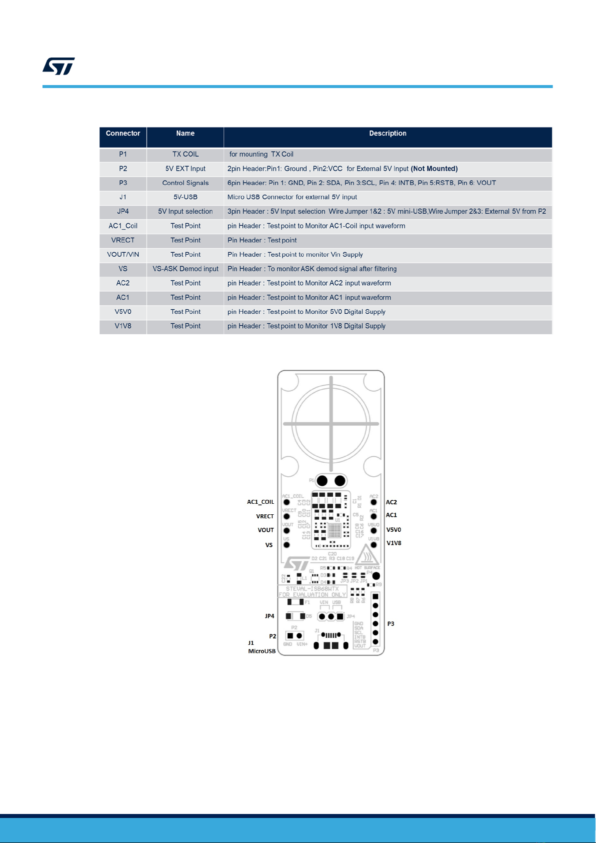


Table of contents
Other ST Microcontroller manuals

ST
ST UC2842B User manual

ST
ST STM32F072 User manual

ST
ST STM32L0 Series Installation and operating instructions

ST
ST STM8L Installation and operating instructions

ST
ST SPIRIT1 User manual

ST
ST STM32F205 series Owner's manual

ST
ST STM8S User manual

ST
ST STEVAL-BCN002V1B User manual

ST
ST UM0250 User manual

ST
ST STM32F746IGT6 User manual

ST
ST STM32H723 User manual

ST
ST STM32F31xx User manual

ST
ST AN3154 Installation and operating instructions

ST
ST X-NUCLEO-53L4A1 User manual

ST
ST STM32G4 Series User manual

ST
ST ST624 B-EMU2 Series User manual

ST
ST PSD4256G6V User manual

ST
ST ST802RT1 User manual

ST
ST STM32 Nucleo User manual

ST
ST P-NUCLEO-WB55 User manual


Popular Microcontroller manuals by other brands

AMS
AMS AS7261 Demo Kit user guide

Novatek
Novatek NT6861 manual

Espressif Systems
Espressif Systems ESP8266 SDK AT Instruction Set

Nuvoton
Nuvoton ISD61S00 ChipCorder Design guide

STMicrolectronics
STMicrolectronics ST7 Assembler Linker user manual

Texas Instruments
Texas Instruments Chipcon CC2420DK user manual


Texas Instruments
Texas Instruments TMS320F2837 D Series Workshop Guide and Lab Manual

CYPRES
CYPRES CY14NVSRAMKIT-001 user guide

Texas Instruments
Texas Instruments INA-DUAL-2AMP-EVM user guide

Espressif Systems
Espressif Systems ESP8266EX Programming guide

Abov
Abov AC33M8128L user manual

Laird
Laird BL654PA user guide