General description and features
1 General description and features
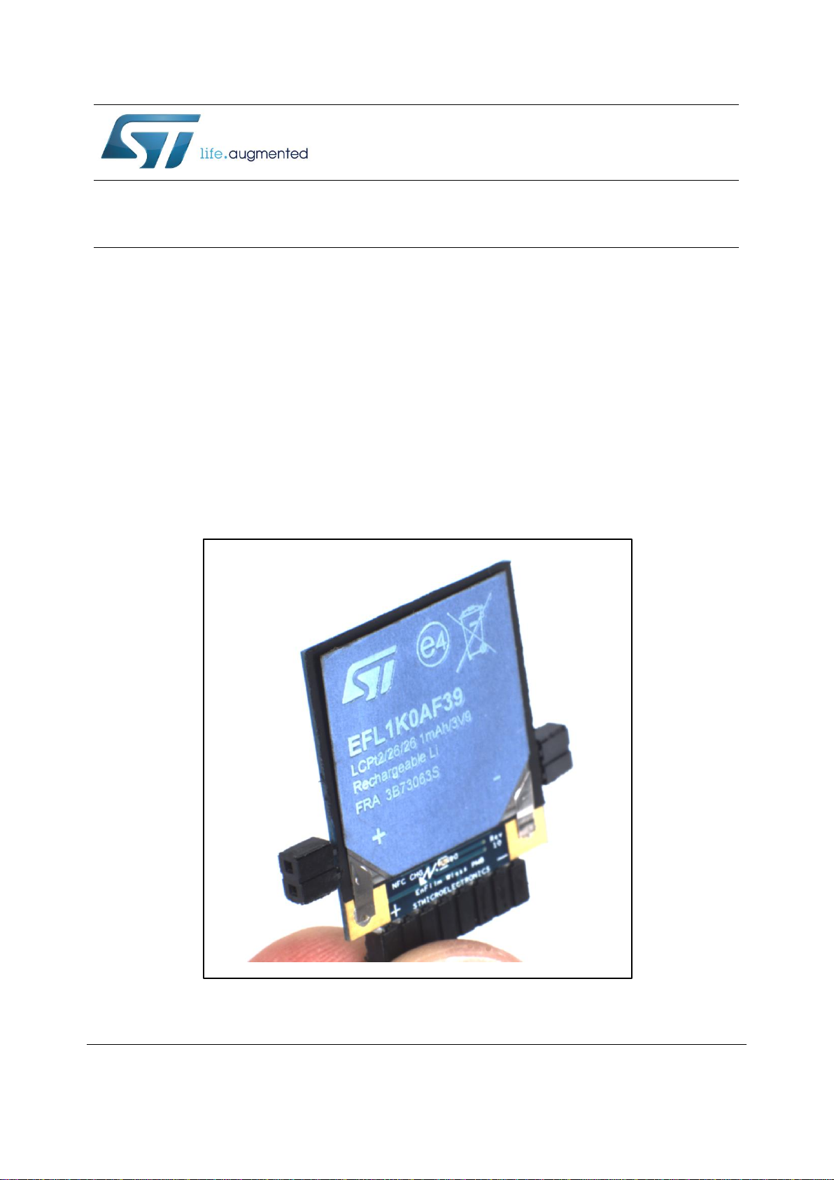
The EnFilm™ EFL1K0AF39 battery brings many benefits compared to conventional
battery:
Low thickness
Fast charge
Low self-discharge
Extremely long calendar and cycle life time
High safety with no risk of burning or explosion
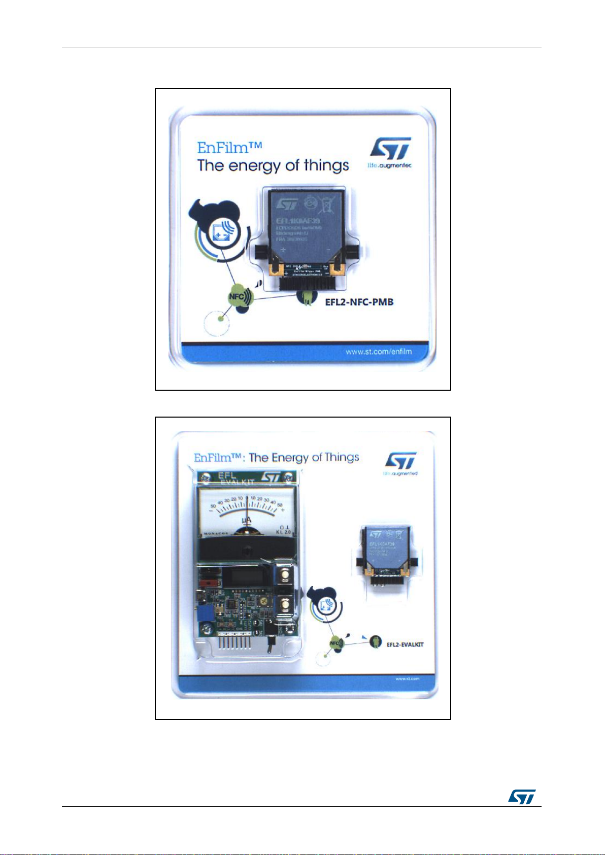
EFL2-NFC-PMB and EFL2-EVALKIT kits were developed to help designers to evaluate the
charge and discharge performances of the EnFilm™ EFL1K0AF39 with a proper setup of
power management.
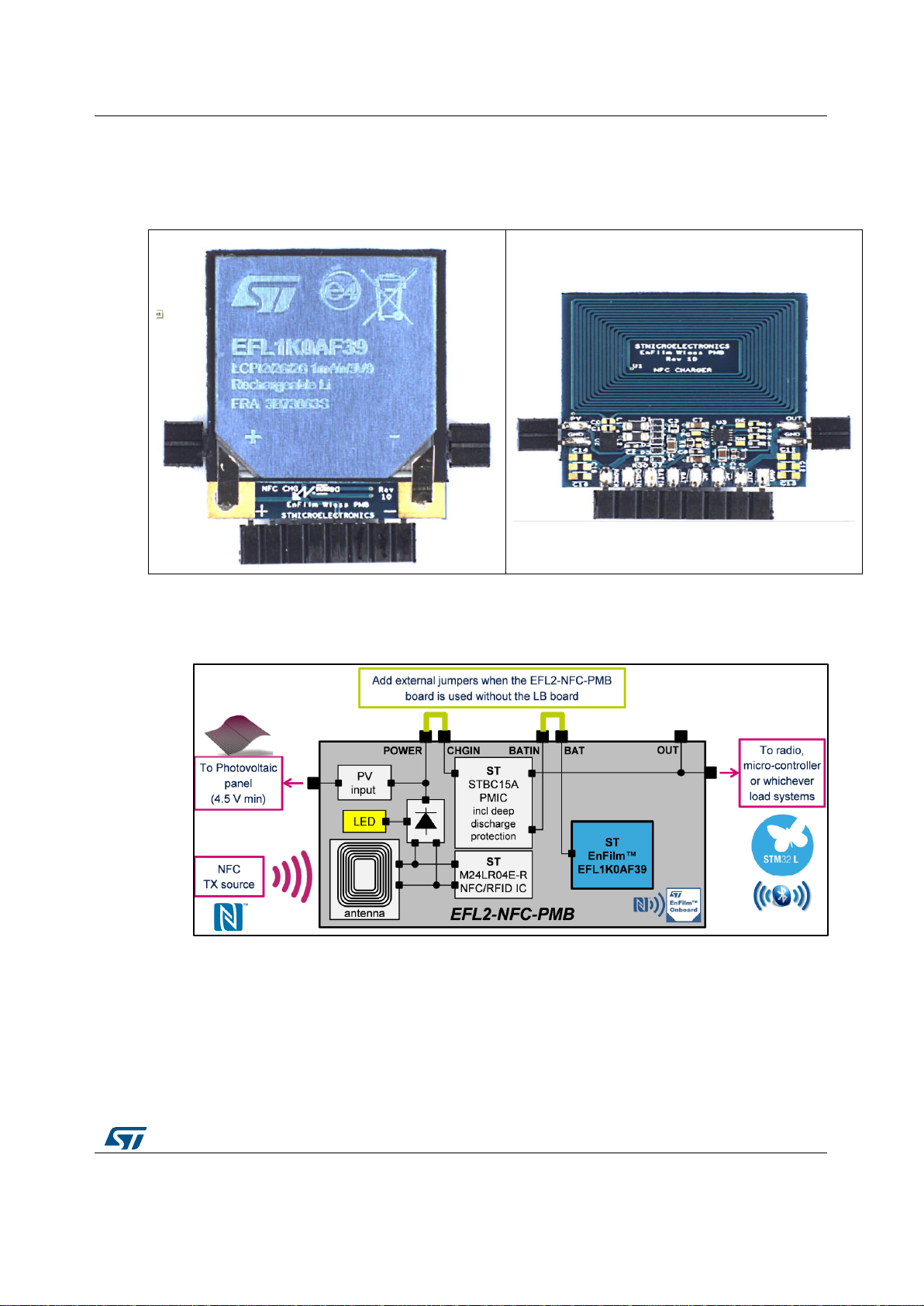
The EFL2-NFC-PMB power management board includes one PCB. It has the same size as
the EFL1K0AF39 battery which is mounted on the top side. It can be charged by different
type of energy source and can be connected to any kind of load with its own power
management circuit.
Whatever the harvester and load system are, the EFL2-NFC-PMB allows a safe and
efficient use of the EFL1K0AF39 micro-battery.
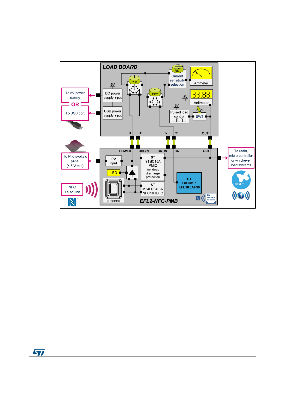
1.1 The EFL2-NFC-PMB power management board
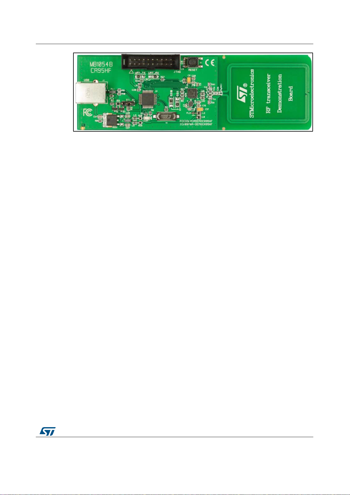
Includes an embedded NFC contact-less smart charger based on the ST M24LR04E-
R dynamic NFC/RFID tag IC for easy and fast EnFilm™ charge
Manages the charge voltage regulation and the deep discharge protection of the
EFL1K0AF39 using an advanced ST ultra-low current consumption power
management IC
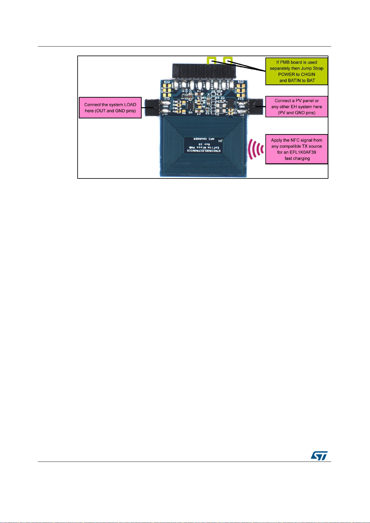
Includes also an additional power input pin for wire plugging of an external charger like
an energy harvesting source or any other power supply (4.5V MIN).
The EFL2-NFC-PMB can be powered by a NFC/RFID reader, a NFC-enabled phone, a
photo-voltaic panel or any kind of harvester with its own power management.
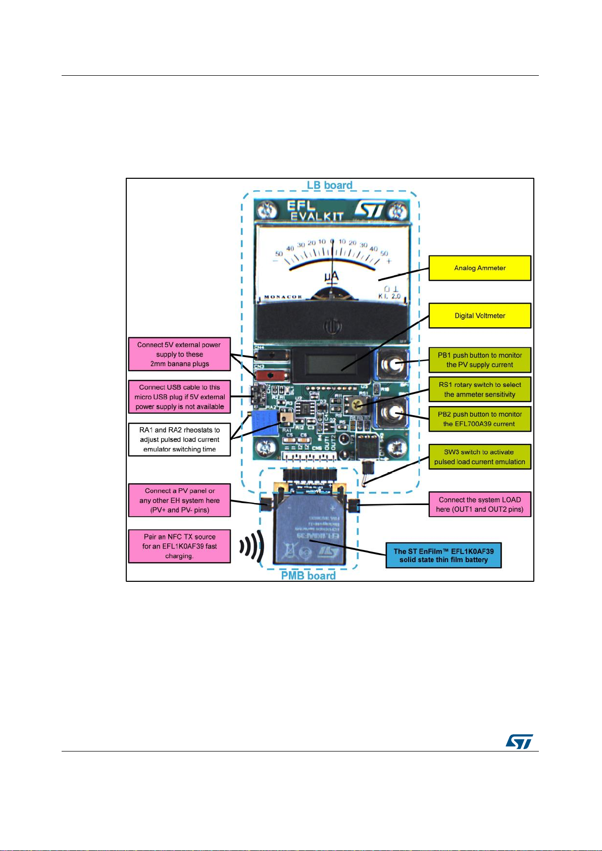
1.2 The EnFilm™ load board from EFL2-EVALKIT
The EnFilm™ load board board is included inside the EFL2-EVALKIT kit together with an
EFL2-NFC-PMB power management board. The EnFilm™ load board embeds:
An analog ammeter and a digital voltmeter allowing the user to monitor:
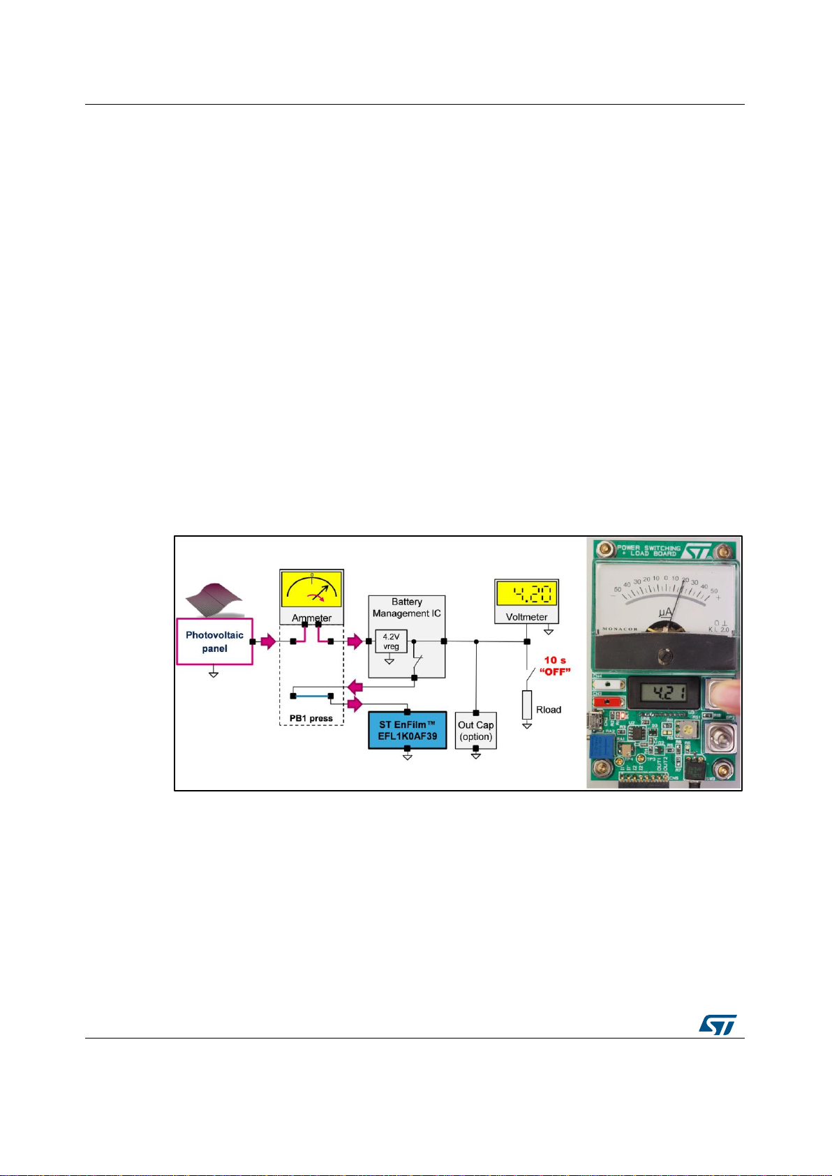
The current delivered by the source by pressing PB1.
The current going through the EFL1K0AF39 battery by pressing PB2.
The battery voltage
A pulsed load emulator with the possibility to adjust the pulsed load cyclic ratio. Its
features are:
Enable / disable function by toggling the switch SW3.
Default pulsed load current set to 5 mA during a pulse time of 100 ms every 10 s.
Tunable pulse duration from 1 ms up to 100 ms through RA1 rheostat.
Tunable pulse repetition time from 1 s up to 10 s through RA2 rheostat.
The LB can be powered via 2 mm banana connectors or a micro-USB plug.
The use of the EnFilm™ load board is recommended to get familiar with operations of
EFL2-NFC-PMB power management board and thus with the EFL1K0AF39 electrical
management characteristics.