ST L5965 User manual
Other ST Motherboard manuals
ST
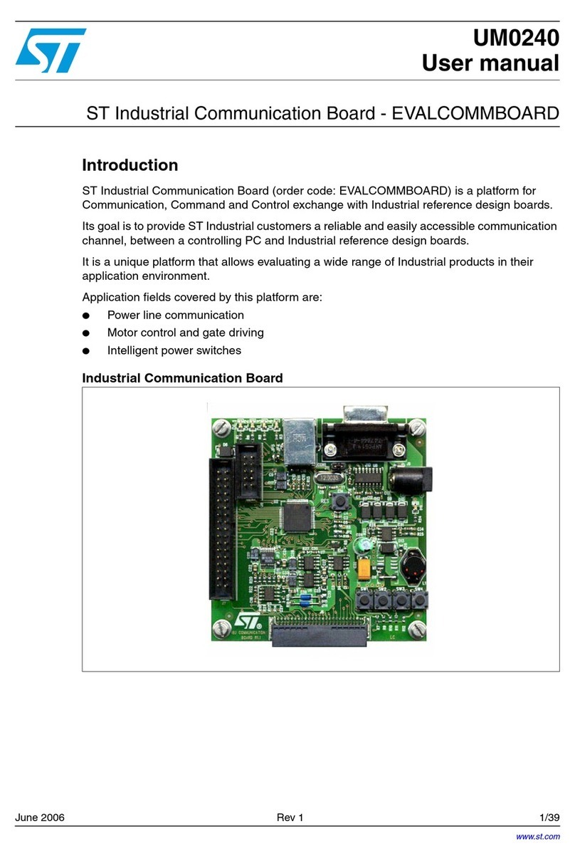
ST EVALCOMMBOARD User manual
ST
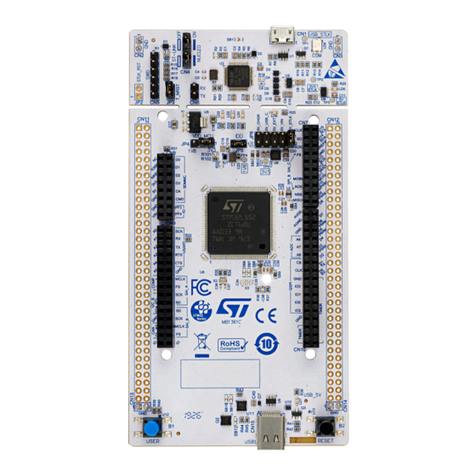
ST STM32L5 Nucleo-144 board User manual

ST
ST STEVAL-SMARTAG2 User manual
ST
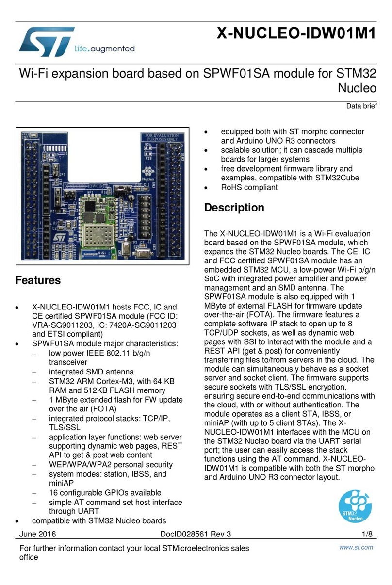
ST X-NUCLEO-IDW01M1 User manual
ST
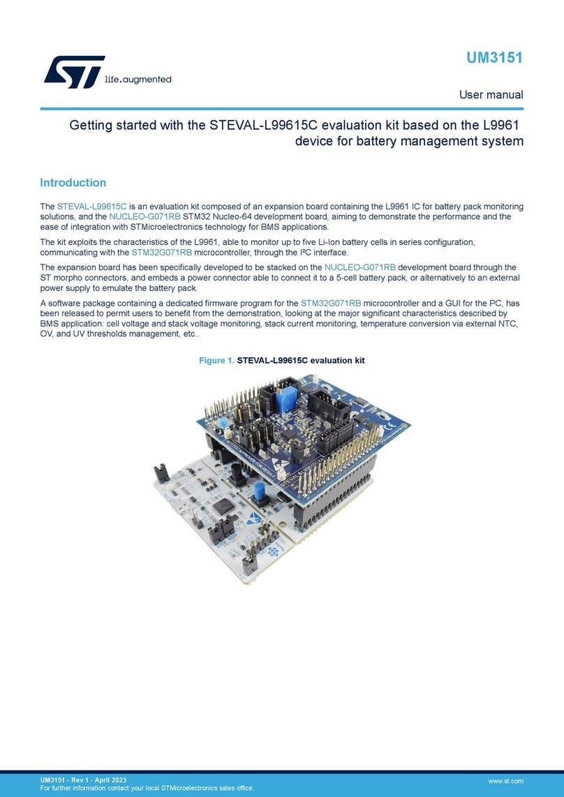
ST STEVAL-L99615C User manual
ST
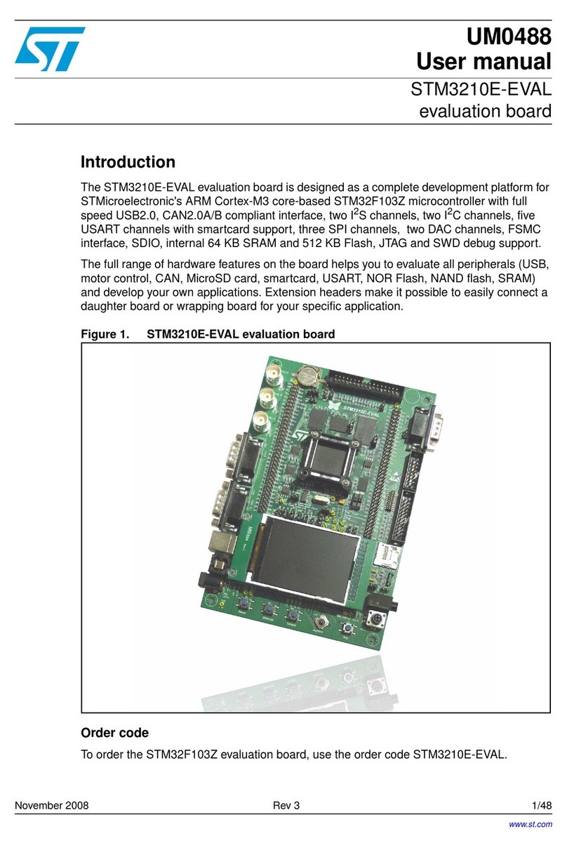
ST STM3210E-EVAL User manual
ST
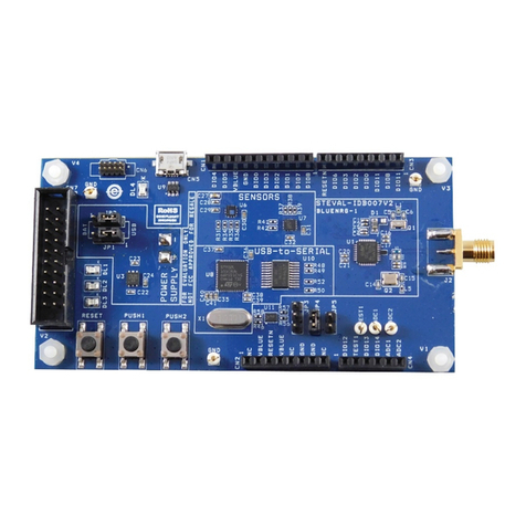
ST STEVAL-IDB007V Series User manual

ST
ST STEVAL-IHM011V1 User manual
ST
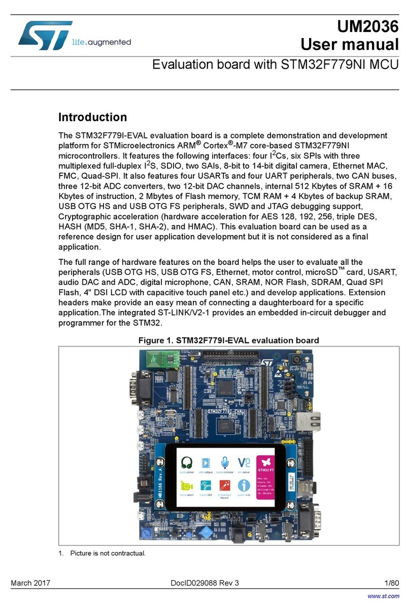
ST STM32F779I-EVAL User manual
ST
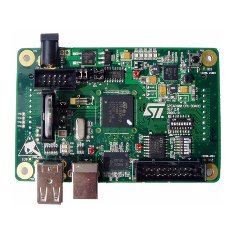
ST EVALSPEAr320CPU User manual
ST
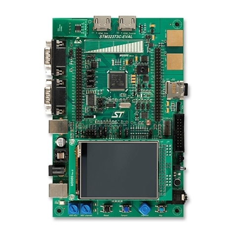
ST STM32373C-EVAL User manual

ST
ST STM32G4 Nucleo-64 User manual
ST
ST EVAL-L9960 User manual

ST
ST STEVAL-ISC005V1 Administrator Guide
ST
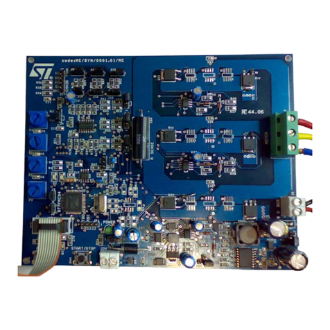
ST STEVAL-IHM015V1 User manual

ST
ST STM32100B-EVAL User manual
ST
ST ST7LIT15BY0 User manual
ST
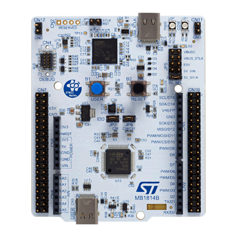
ST STM32H5 User manual
ST
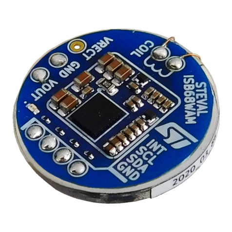
ST STEVAL-ISB68WA User manual
ST
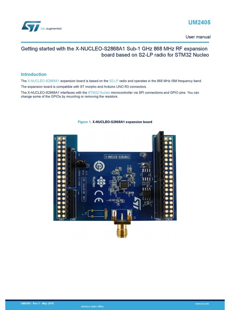
ST X-NUCLEO-S2868A1 User manual
