Getting started with EVAL-L9958 AN4627
6/11 DocID027205 Rev 1
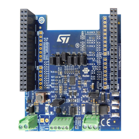
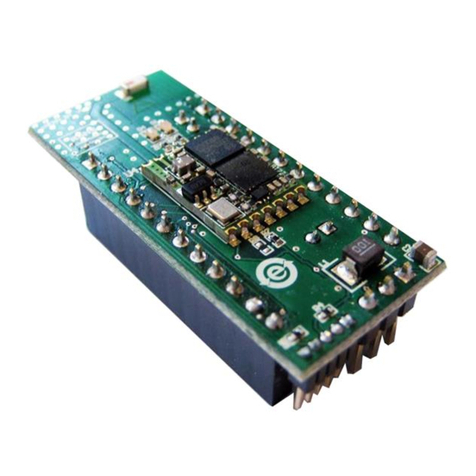
The board comes already configured and the it works properly if plugged in a SPC56x
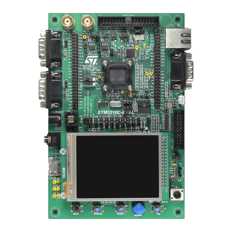
Discovery+ board. Adding some wires, the board can be driven using SPCDiscovery board
(SPC560B-DIS or SPC560B-DIS) or a different microcontroller evaluation board
Table 2 shows jumper name, the function and the default configuration.
The external PSU must be connected to the VBatt terminal blocks following the polarity
indication on top of the board (check the silkscreen).
VBatt level must be selected in accordance with the motor connected to the outputs as well
as the PSU current capability. The VBAT voltage level must be lower than the maximum
operative voltage of the L9958. The LED D6 is turned on when the board is supplied and
VBAT is ON; the LED D2 highlights the VDD status.
The load (motor) must be connected to J5.
The load connections as well as all the wires must be connected to the board when the
board is not supplied.
Table 1. Microcontroller connector (J8) – Pin description
Pin name Description
A22 PWM input signal
C17 DI input signal
C18 DIR input signal
C26 SI input signal
D17 EN input signal
D18 CS - SPI
D25 SCK - SPI
D18 SO - SPI
C33 VDDIO
A34 GND
Table 2. Jumpers: description and default configuration
Jumper name Description Default config
J2 DIR setting
(from uC, VDDIO, GND or external source)
2-3
(µController)
J3 EN Setting
(from uC, GND or external source)
1-2
(µController)
J4 VDD setting
(from internal regulator or VDDIO)
ON
(+5V)
J6 VDD setting:
(from VDDIO or external source) OFF
