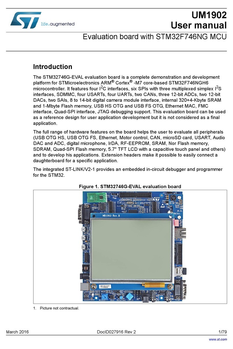
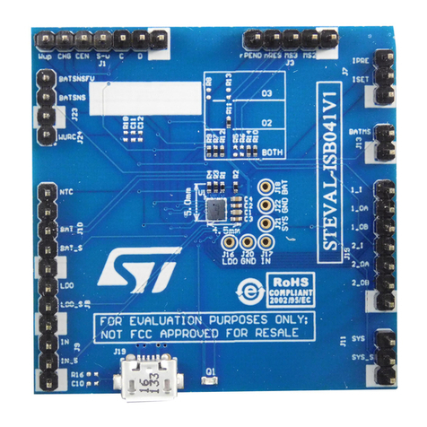
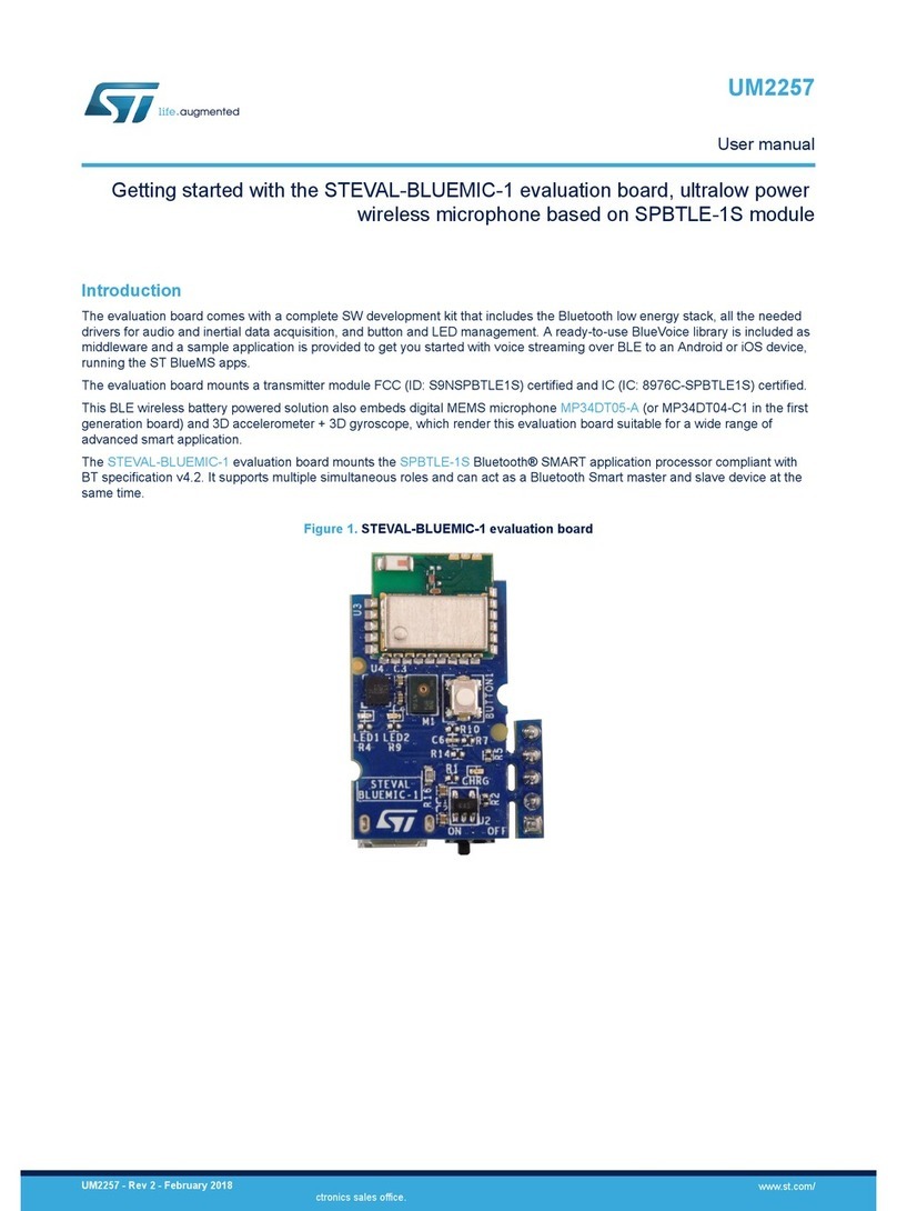
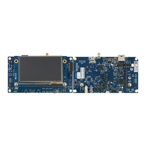
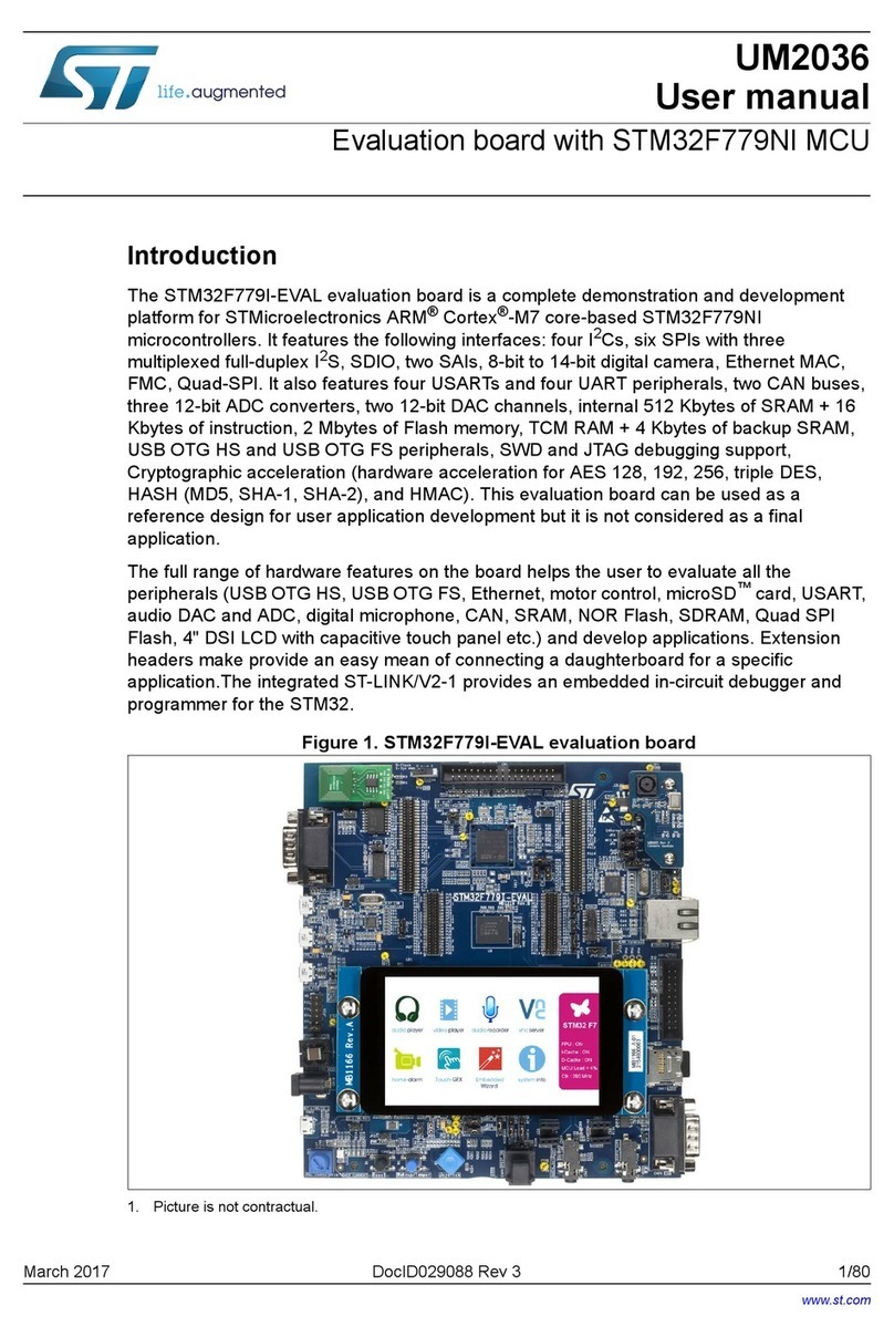
ST STEVAL-ISF003V1 User manual

July 2016
DocID029457 Rev 1
1/43
www.st.com
UM2076
User manual
Getting started with the STEVAL-ISF003V1
Introduction
The STEVAL-ISF003V1 evaluation board allows the inrush-current which charges a DC bus capacitor to
be limited to comply with standard IEC 61000-3-3. This inrush current limitation is based on a soft-start
procedure of the mixed bridge diodes and SCRs rectifier using progressive phase control at board start-
up.
This solution can also drastically reduce standby losses as the DC bus can be totally disconnected from
the AC mains when it does not have to operate. DC bus deactivation is simply achieved by turning off
SCRs, without requiring an additional relay to open the circuit in standby.
The steady-state losses are also reduced, thanks to the removal of the NTC / PTC resistor traditionally
used to limit inrush current. Also in this case, no relay is required to bypass this resistor as it is no longer
used.
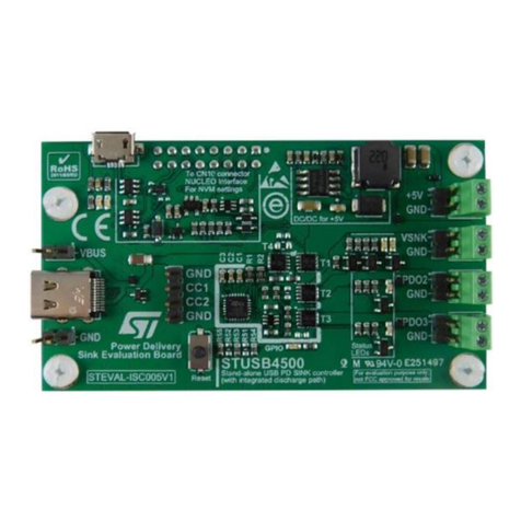
Figure 1: STEVAL-ISF003V1 board (top view)

Contents
UM2076
2/43
DocID029457 Rev 1
Contents
1Demonstration board overview......................................................6
1.1 What does this demoboard aim to demonstrate?..............................6
1.2 STEVAL-ISF003V1 functional blocks................................................6
1.3 Target applications............................................................................7
1.4 Main part numbers............................................................................7
1.5 Operating range................................................................................7
1.6 Performance characteristics..............................................................8
1.7 Standby consumption........................................................................9
2Getting started...............................................................................11
2.1 Safety instructions...........................................................................11
2.2 Board connection and start-up........................................................11
2.3 DC bus capacitor discharge for demonstration purposes................13
2.4 LED indications...............................................................................13
2.5 Possible board variations................................................................14
2.5.1 EMI filter and DC bus capacitor alteration........................................ 14
2.5.2Power factor circuit connection ........................................................ 14
2.5.3 Motor inverter connection................................................................. 15
2.5.4 Control with an external microcontroller........................................... 15
3Schematic diagrams......................................................................17
4STEVAL-ISF003V1 power supplies and typical consumption....20
5Inrush-current limitation...............................................................22
5.1 IEC 61000-3-3 overview..................................................................22
5.2 STEVAL-ISF003V1 compliance with the IEC 61000-3-3 limit.........22
6Mains voltage dips and interruptions ..........................................26
7AC voltage monitoring and zero-voltage synchronization.........30
7.1 Zero voltage and AC line voltage sensor circuits ............................30
7.2 Zero AC line voltage detection........................................................31
8SCR switch insulated control.......................................................32
9EN55014 test results .....................................................................34
10 STEVAL-IHT008V1 silk-screen .....................................................35
11 Bill of materials..............................................................................36
12 Test points.....................................................................................40
List of tables
UM2076
4/43
DocID029457 Rev 1
List of tables
Table 1: Power sources from flyback converter .........................................................................................7
Table 2: Comparison of standby losses....................................................................................................10
Table 3: Typical STEVAL-ISF003V1 control-circuit consumption ............................................................20
Table 4: Maximum input RMS current variation for 230 V single-phase grid according to IEC 61000-3-3
..................................................................................................................................................................22
Table 5: Dip and interruption tests and STEVAL-ISF003V1 performance...............................................27
Table 6: Document revision history ..........................................................................................................42

UM2076
List of figures
DocID029457 Rev 1
5/43
List of figures
Figure 1: STEVAL-ISF003V1 board (top view)...........................................................................................1
Figure 2: STEVAL-ISF003V1 functional block diagram..............................................................................6
Figure 3: Connection of a PFC at the HVDC output...................................................................................8
Figure 4: Inrush current at STEVAL-ISF003V1 start-up on 230 V line (1 mF output DC capacitor)..........9
Figure 5: Solution using relays to limit the inrush current and standby losses...........................................9
Figure 6: J1 jumper plugged on board (bypass mode).............................................................................11
Figure 7: J1 jumper position left free (phase control mode) .....................................................................12
Figure 8: AC line connections...................................................................................................................12
Figure 9: HVDC switch..............................................................................................................................13
Figure 10: PFC activation permission (PFC_Start signal) when the HV output capacitor is charged......15
Figure 11: STEVAL-IFS003V1 power and insulated control schematic...................................................17
Figure 12: STEVAL-ISF003V1 control circuit schematic..........................................................................18
Figure 13: STEVAL-ISF003V1 flyback SMPS schematic.........................................................................19
Figure 14: Typical output characteristics of the 5 V and 15 V positive supplies (5V_DC/15V_DC).........21
Figure 15: Typical output characteristics of the 5 V positive supply (VCC_AC).......................................21
Figure 16: HV capacitor charging controlled ............................................................................................23
Figure 17: SCR current zoom for the highest peak current during start-up..............................................24
Figure 18: Triac current for the highest peak current during start-up.......................................................25
Figure 19: Board operation during 1-cycle line interruption......................................................................28
Figure 20: Board operation during 2-cycle line interruption......................................................................29
Figure 21: AC line voltage measurement principle...................................................................................30
Figure 22: Zero AC line voltage crossing detection..................................................................................31
Figure 23: SCR switch insulated control...................................................................................................32
Figure 24: EMI noise test with 2000W load..............................................................................................34
Figure 25: EMI noise test with no load......................................................................................................34
Figure 26: STEVAL-IHT008V1 silk-screen...............................................................................................35

Demonstration board overview
UM2076
6/43
DocID029457 Rev 1
1 Demonstration board overview
1.1 What does this demoboard aim to demonstrate?
The STEVAL-ISF003V1 is a standalone board designed to demonstrate efficient trade-offs
regarding:
inrush-current limitation without inrush-current resistors
standby losses in line with ECO European directive.
The STEVAL-ISF003V1 board is also a development tool for designing broad inrush-
current reduction systems (EV chargers, telecom power supply, etc.). For this purpose,
connectors are available for an external power factor corrector, an intelligent power module
(IPM), or for an external microcontroller (see Section 4.5: "Possible board variations").
1.2 STEVAL-ISF003V1 functional blocks
Figure 2: STEVAL-ISF003V1 functional block diagram
See Section 5: "Schematic diagrams" for detailed schematics.

UM2076
Demonstration board overview
DocID029457 Rev 1
7/43
The principal sections of the STEVAL-ISF003V1 board are:
1. T1 and T2 silicon-controlled rectifiers (SCRs) in the mixed rectifier bridge.
2. The MCU, which drives SCRs through opto-transistors (see APPENDIX 6) and can
also activate any supply or motor inverter referenced to the DC bus ground (GND_DC)
in a final application.
3. The flyback power converter providing the sources in the table below.
Table 1: Power sources from flyback converter
Source
Output
Ground
Destination
Maximum output
current
VCC_AC
5 V
GND_AC is
connected to the
HVDC bus
control SCRs (T1 and T2)
200 mA
5V_DC
+5 V
referenced to the
DC bus Ground
(GND_DC)
MCU and control circuits
90 mA
15V_DC
+15 V
referenced to the
DC bus Ground
(GND_DC)
can supply an IPM to control a
three-phase motor in a final
application
500 mA (together
with 5V_DC
consumption)
VCC_INS
+5 V
insulated output
for components which must be
insulated from the mains voltage,
(e.g., sensors). Not used on the
demoboard
90 mA
For further information regarding the SMPS outputs, please refer to Section 6: "STEVAL-
ISF003V1 power supplies and typical consumption".
1.3 Target applications
Target applications include all those using a diode-bridge to rectify the AC line voltage,
where NTC or PTC resistor removal and loss reduction in standby are desirable, such as:
EV chargers.
Telecom power supplies.
1.4 Main part numbers
The references of the main part-numbers used in this demoboard are:
Inrush-current-limiter SCRs: TN5050H-12WY
Rectifier diodes: STBR6012WY
Microcontroller unit (MCU): STM8S003F3
Flyback IC: VIPER26LD
1.5 Operating range
The STEVAL-ISF003V1 board is designed to operate inside following operating ranges:
RMS line voltage range:85 to 264 VRMS
Line voltage frequency range: 45 to 65 Hz
Ambient temperature range is: 0 to 60 °C (heatsink fans keep junction temperature of
bridge components below Tjmax)
Maximum input current: 32 ARMS (7.4 kW input power for operation on 230 VRMS and
3.6 kW input power on 120 VRMS).

Demonstration board overview
UM2076
8/43
DocID029457 Rev 1
Allowed DC output capacitor (or DC bus capacitor): up to 2 mF. This value is the
equivalent of all capacitors in parallel at the bridge output, like C3 and CPFC at the PFC
in the figure below. If an interleaved PFC is used, all the output capacitors of each
PFC must be added.
Figure 3: Connection of a PFC at the HVDC output
1.6 Performance characteristics
Efficiency at 230 V 50 Hz 3.3 kW (with output DC resistive load @ COUT = 1mF) >
98%
Efficiency at 120 V 60 Hz 3.3 kW (with output DC resistive load @ COUT = 1mF) > 98
%
Standby losses < 300 mW (see Section 3.7: "Standby consumption")
Compliance with IEC 61000-3-3 (with MAX_INRUSH CURRENT potentiometer set to
default position, see Section 7: "Inrush-current limitation")
Compliance with EN55014 (CIPSPR 22 method B, see Section 11: "EN55014 test
results")
IEC 61000-4-4: 2 kV criteria A, SCR1 and SCR2 withstands a level of 5 kV without
triggering. This avoids undesired triggering and uncontrolled inrush current in case of
EMI noise.
IEC 61000-4-5: 4 kV
IEC61000-4-11: criteria A for dips down to 100% of the line voltage during 1 cycle;
criteria B for interrupts up to 300 cycles or more (see Section 8: "Mains voltage dips
and interruptions").
The figure below shows an example of the progressive DC capacitor charge which is
ensured by SCR1 and SCR2. The test is performed at start-up when the STEVAL-
ISF003V1 board is connected to a 230 V, 50 Hz grid (VAC), while the output DC capacitor is

UM2076
Demonstration board overview
DocID029457 Rev 1
9/43
completely uncharged (its initial voltage is null). The output DC capacitor connected to the
demonstration board is 1 mF.
The output capacitor is charged over 900 ms while the input RMS current (2.8 A) remains
far below the 16.1 A (IAC). The input RMS current easily complies with the IEC 61000-3-3
standard.
Figure 4: Inrush current at STEVAL-ISF003V1 start-up on 230 V line (1 mF output DC
capacitor)
1.7 Standby consumption
Mixed SCR/Diode rectifier bridges prevent undesirable standby losses through full bridge
disconnection by simply turning off the SCRs; this would otherwise require a front-end
relay, like S2 in the figure below, to achieve.
Figure 5: Solution using relays to limit the inrush current and standby losses
To appreciate the benefits of bridge disconnection, we measured the typical losses of the
STEVAL-ISF003V1 board in standby mode for the following cases:

Demonstration board overview
UM2076
10/43
DocID029457 Rev 1
1. STEVAL-ISF003V1 board (without modifications) with SCRs in the OFF state (SW2
HVDC switch in OFF position) and the J1 bypass mode jumper is unplugged (PTC not
connected).
2. Same as 1, but the following circuits used for demonstration purposes and which
consume undesired power in standby are disconnected:
HV Capacitor Discharge circuit: R5 and R6 are disconnected from the DC bus
D6 HVDC LED: D1 is disconnected from the DC bus
D14 POWER_ON LED: R44 is disconnected
3. Same as 2, but the J1 bypass jumper is plugged (PTC connected) to simulate the
losses for a conventional solution using only one PTC (EPCOS B59107J0130A020).
Table 2: "Comparison of standby losses" gives the experimental results for the above
cases with 230 and 120 V line voltages and a 2-mF HV output capacitor connected to the
demonstration board. The test results clearly show that the mixed SCR/Diode bridge
rectifier is the only solution with power consumption lower than 0.5 W, as currently required
by European directive 2005/32/EC.
The losses on this demonstration board are mainly due to:
resistors R54, R55 and R56 to discharge the HV output capacitor
resistors R7 and R9 and the current source to control HVDC LED indicating HVDC
voltage
resistors R6 and R9 to accelerate the HV output capacitor discharge time connected
to the demonstration board output
the other R24, R25 and R28 resistor divider circuit to sense the HVDC voltage
The HVDC voltage is monitored to ensure proper soft-start operation and avoid the DC
capacitor charging too long (e.g., a load is kept connected to the DC bus before start-up).
In standard circuits, such a voltage sensor is often required (e.g., to start the PFC or the
DC/DC supplies).
The losses for a 230 V rectified voltage are:
140 mW for the discharge circuit
500 mW for the HVDC LED circuit
180 mW for the acceleration circuit to discharge the HV output capacitor connected to
the demonstration board output
52 mW for the HVDC sense.
Table 2: Comparison of standby losses
case
SCR
status
PTC
status
circuits
power consumption (mW)
Power
LED
HVDC
LED
HV capacitor
discharge
circuit
VAC=230
VRMS,
CHVout=2 mF
VAC=120
VRMS,
CHVout=2 mF
1
OFF
OFF
connected
270
200
2
OFF
OFF
disconnected
200
140
3
OFF
ON
disconnected
500
200

UM2076
Getting started
DocID029457 Rev 1
11/43
2 Getting started
2.1 Safety instructions
The high voltage levels used to operate the STEVAL-IHT008V1 evaluation board
may present a serious electrical shock hazard. This evaluation board must be
used in a suitable laboratory and only by qualified personnel who are familiar with
the installation, use, and maintenance of power electrical systems. The STEVAL-
ISF003V1 evaluation board is designed for demonstration purposes only and
must not be used for either domestic installation or industrial installation.
2.2 Board connection and start-up
To reduce inrush current by operating the board with the PTC, plug jumper J1 as indicated
by the silk-screen and in the following figure.
Figure 6: J1 jumper plugged on board (bypass mode)

Getting started
UM2076
12/43
DocID029457 Rev 1
To control the inrush current with SCRs, do not plug the J1 jumper.
Figure 7: J1 jumper position left free (phase control mode)
Connect L, N and PE (if required) on the respective J3, J6 and J7 headers to an un-
powered mains plug.
Figure 8: AC line connections
Switch on the mains voltage; from this moment, do not make any contact with live parts
under line voltage.
The Power_ON LED lights red to indicate the demoboard is powered. The ICL-STATUS
LED first lights red, then orange, then green and finally turns off to indicate the board is
operational. This occurs each time the board is connected to the AC line and the C39
capacitor (5V_DC) is discharged.

UM2076
Getting started
DocID029457 Rev 1
13/43
Toggle the HVDC switch ON to start charging the DC capacitors.
Figure 9: HVDC switch
When J1 jumper is unplugged, DC capacitor charging can be accelerated if the
allowed peak current is increased by rotating the MAX-INRUSH CURRENT
potentiometer knob clockwise.
2.3 DC bus capacitor discharge for demonstration purposes
With default STEVAL-ISF003V1 output 47 nF capacitor (C3) and associated 470 kΩ
resistors (R54, 55, and R56) used in parallel to discharge the C3 capacitor, the DC bus
discharging time is a few milliseconds, if no load is connected.
For larger C3 capacitors, a circuit with MOSFET Q2 and resistor R5 is implemented to
accelerate this discharging time, especially when several start-ups are required over a
short interval for test or demonstration purposes. Q2 remains on while the SW1 SPDT
toggle switch (marked HV CAPACITOR DISCHARGE on the PCB) is set to the momentary
ON position.
For a 2-mF C3 capacitor, the full discharge time is around 15 seconds. In this case, the
SW1 switch must be kept at the momentary ON position for these 15 seconds, at least.
The D6 LED (marked HVDC on the PCB) remains lit while the HVDC voltage remains
above 50 V; as soon as this LED turns off, switch SW1 can be released and a new start-up
can begin.
2.4 LED indications
Several status LEDs on the board provide useful information.
ICL-STATUS (LED D1):
On board plug-in, the LED lights red, then orange, then green and finally then off
to indicate that the microcontroller has finished the start-up procedure (correct
mains connection, line frequency measurement, power supply available, etc.) and
the board is ready. The DC output capacitor can now be charged when the
HVDC switch (SW6) is toggled ON.
Green flashing: the DC bus capacitors are charging (flashing starts when the
HVDC switch is toggled ON and ends when the DC bus capacitors are fully

Getting started
UM2076
14/43
DocID029457 Rev 1
charged). This flashing mode can last less than one second and may therefore
not be perceived.
Green: DC bus is charged to the right voltage.
Orange flashing: the DC bus capacitors are charging, but the rate of increase of
the output DC voltage is too low. This may occur when a load connected to the
HVDC bus sinks too much current for the DC capacitor to charge efficiently.
Orange: the LED stops flashing and remains lit orange if the output DC capacitor
is not charged to the peak line voltage. This may occur if the bridge is started but
a power load is already connected to the HVDC bus and sinks too much current
for the DC capacitor to fully charge.
Red flashing: the MCU detected an error (e.g., line voltage outside 85 to 264 V
operating range or line frequency outside 45 to 65 Hz operating range).
HVDC (LED6): lights red when the voltage between HVDC and GND_DC terminals is
higher than 50 V (see Section 4.3: "DC bus capacitor discharge for demonstration
purposes").
POWER_ON (LED14): lights when the AC line is plugged to the AC line.
2.5 Possible board variations
The STEVAL-ISF003V1 board allows some external components to be added to the front-
end circuit so designers can evaluate entire systems.
2.5.1 EMI filter and DC bus capacitor alteration
The EMI filter and DC capacitors are simple through-hole devices so they are easy to
change. This allows a designer to adapt the EMI filter and HVDC voltage ripple to specific
application requirements (e.g., the power rating).
However, if these components are modified, the SCR control law must be updated to
maintain IEC 61000-3-3 compliance. This can be done by adjusting the maximum peak
current during start-up with the MAX-INRUSH CURRENT potentiometer. When this
potentiometer is turned clockwise, the SCRs are turned on sooner (according to the AC line
polarity) at each half-cycle, leading to a higher peak current.
Maximum RMS current or voltage fluctuation (if a normalized line impedance is used) must
then be measured according to the potentiometer position to check IEC 61000-3-3
compliance.
If the EMI filter capacitor (C4 to C9) values are increased, R10 and R12 values
may be decreased to ensure that the capacitors still discharge down to a safe
voltage (120 V for DC voltage) in less than one or two seconds. Indeed, the EMI
filter capacitor voltage is applied to the power plug when the board is unplugged
and, if the power terminals have accessible live parts, you may be vulnerable to
electric shock.
2.5.2 Power factor circuit connection
A PFC can be connected on the HVDC bus via the HVDC (J2) and GND_DC connections
(J8). Capacitor C3 must be unsoldered by using a 630 V DC film capacitor if needed.
As SCRs are alternately controlled by a DC gate current (according to AC line polarity),
when the HVDC voltage reaches its steady-state value, either a discontinuous mode or a
continuous mode PFC can be used.
For proper STEVAL-ISF003V1 front-end circuit operation, the PFC must be activated after
the PFC_START signal is set to a low level (see Figure 10: "PFC activation permission
(PFC_Start signal) when the HV output capacitor is charged", indicating that the PFC HV

UM2076
Getting started
DocID029457 Rev 1
15/43
output capacitor is charged. This signal is referenced to GND_DC terminal and is available
from the J16 header.
The PFC_START signal is an open drain output that must be compatible with the digital rail
used by an external system. The PFC DC storage capacitor (CPFC in Figure 3: "Connection
of a PFC at the HVDC output") must be inside the range specified in Section 3.5:
"Operating range ".
Connector J13 gives the rectifier AC line voltage and can be used to by an
external PFC to shape the input current waveform.
Figure 10: PFC activation permission (PFC_Start signal) when the HV output capacitor is
charged
2.5.3 Motor inverter connection
An inverter or any other DC/DC power converter can be added after the PFC or directly
behind the HVDC bus output.
A 15 V positive output referenced to the DC Bus Ground (GND_DC) is available on header
J11 to supply an IPM module if needed. The maximum current sunk from this supply must
be well below the limit in .
2.5.4 Control with an external microcontroller
You can control the STEVAL-ISF003V1 front-end circuit with an external MCU instead of
the embedded STM8S003F3 MCU to directly check the compliance of your own firmware
with this kind of circuit.
All the control signals required to drive the SCRs are available on the J16 header.
EC_SCR1 and EC_SCR2 are the connections to externally drive SCR1 and SCR2,
respectively. GND_DC of the DC bus ground and the ZVS_ext signal (to synchronize the
control signals of the external MCU) are also available on this header.

Getting started
UM2076
16/43
DocID029457 Rev 1
For correct operation with external signals, Jumpers J9 and J10 (marked as
INT/EXT_CONTROL on the PCB) must be removed to disconnect the opto-Transistor input
LEDs from the U7 microcontroller outputs (see SCRs gate ctrl section in Section 5:
"Schematic diagrams").
It is also possible to control the STEVAL-ISF003V1 front-end circuit with an external MCU
by using the embedded STM8S003F3. In this case, the inrush current limitation is
managed by the embedded STM8S003F3 MCU. The control signal required to start the
inrush current limitation is available on J16 header (HVDC_EXT).
the input HVDC_EXT signal is 3.3V/5V compatible.

UM2076
Schematic diagrams
DocID029457 Rev 1
17/43
3 Schematic diagrams
Figure 11: STEVAL-IFS003V1 power and insulated control schematic

Schematic diagrams
UM2076
18/43
DocID029457 Rev 1
Figure 12: STEVAL-ISF003V1 control circuit schematic

UM2076
Schematic diagrams
DocID029457 Rev 1
19/43
Figure 13: STEVAL-ISF003V1 flyback SMPS schematic

STEVAL-ISF003V1 power supplies and typical
consumption
UM2076
20/43
DocID029457 Rev 1
4 STEVAL-ISF003V1 power supplies and typical
consumption
The table below gives the typical current consumed from the 5V_DC output for the different
STEVAL-IFS003V1 operating modes.
Table 3: Typical STEVAL-ISF003V1 control-circuit consumption
Operating mode
Current sunk from
5V_DC (mA)
MCU in standby mode (SCRs off)
Power_ON LED connected
2.9
Power_ON LED not connected
0.7
MCU in standby mode (SCRs on)
Power_ON LED connected
27.6
Power_ON LED not connected
25.4
Table 1: "Power sources from flyback converter" lists the following flyback output supplies:
a non-regulated 5 V VCC_AC supply for SCR control
+15 V and +5 V supplies (15V_DC and 5V_DC outputs) supply circuits referenced to
the DC bus Ground (MCU, IPM if added)
a +5 V insulated supply (VCC_INS/GND_INS) for sensors if needed, this output is not
implemented by default
Only the +15 V output is regulated by the VIPer26LD circuit, as this supply is always
loaded when the other outputs are loaded. The two +5 V supplies (5V_DC, VCC_INS) are
also regulated thanks to two LM2931 positive voltage regulators.
The VCC_AC level is not regulated: its voltage level will be higher if it is not loaded and if
the +15 V supply is loaded with its maximum current.
The current capabilities of the different outputs are (for the whole operating range):
For 5V_DC: 90 mA
For VCC_AC (non-regulated 5 V negative output): 200 mA
For 15V_DC: 500 mA (with 5V_DC consumption included)
For VCC_INS (optional 5 V regulated output): 90 mA
A +12 V supply is implemented to supply the fan to control the SCR/diode rectifier
bridge temperature; it is regulated through the L78M12 device from the 15V_DC
positive supply.
The two figures below give the typical output voltage according to the current sunk from
each output. The measurements were taken with the STEVAL-ISF003V1 connected to 230
V and 120 V lines for the whole temperature operating range (0 to 60 °C). The 15 V_DC,
and the 5 V outputs (5V_DC and VCC_INS) are well regulated by the VIPer26LD and
LM2931 devices, respectively.
For the VCC_AC, four curves provide the minimum and maximum values of this output
when the MCU and fan are ON and OFF, respectively. For these two cases, the minimum
voltage is reached when no current is sunk from the 15V_DC, and the maximum voltage is
reached when a 500 mA maximum current is sunk from the 15V_DC.
Table of contents
Other ST Motherboard manuals

ST
ST STEVAL-L99615C User manual

ST
ST STM32F3DISCOVERY User manual

ST
ST STEVAL-USBPD45H Administrator Guide

ST
ST STEVAL-L6982CDR User manual

ST
ST STEVAL-IHM020V1 User manual

ST
ST STEVAL-WBC86TX User manual

ST
ST STEVAL-IPMM10B User manual

ST
ST STEVAL-IHP007V1 User manual

ST
ST NUCLEO-H745ZI-Q User manual

ST
ST STM32 Nucleo User manual

ST
ST EVAL-L9963-MCU Installation and operating instructions

ST
ST STM32 Nucleo-32 User manual

ST
ST EVALSTPM34 User manual

ST
ST STEVAL-IPMnM1S User manual

ST
ST STM3220G-EVAL User manual

ST
ST STR730-EVAL User manual

ST
ST STMPE821 User manual

ST
ST AN3954 Installation and operating instructions

ST
ST STEVAL-IFS001V1 User manual

ST
ST SPC572LADPT80S User manual