UM1659 Rev 4 7/25
UM1659 Getting started
24
2.5 License registering and activation of SPC5-UDESTK
The starter kit version of SPC5-UDESTK can be used for an evaluation purposes without
registration. In this case, the SPC5-UDESTK is restricted to a limited code size for
downloading of 256 kBytes.
The registered version of SPC5-UDESTK unlocks the limitation of code size downloading.
STMicroelectronics offers licenses with a validation period of 1 year with option to extend to
further 2 years. For the purchase of a license, please visit ST web site and search for SPC5-
UDEDEBG or SPC5-UDEDEBG-TL.
For activation of a new SPC5-UDESTK license or an extended SPC5-UDESTK license,
please send the following information via the PLS website form at:
http://www.pls-mc.com/spc5-udestk
1. Company data
2. Customer data
3. Host PC’s MAC (Media Access Control) address
4. Serial number of PLS USB/JTAG adapter for SPC5 (see the sticker backside of the
adapter)
5. Activation code, delivered by STMicroelectronics
After that, the license file will be delivered by PLS.
Note: SPC5-UDESTK functionality is guaranteed only for ST evaluation boards. Visualization
functions at runtime and script support are not supported features.
2.6 Installing hardware
2.6.1 Static electricity precautions
Electrostatic Discharge (ESD) can damage a sensitive electronic component. Under several
conditions static electricity and ground potential differences between the host PC, the
SPC5-UDESTK PLS USB/JTAG adapter for SPC5 and the user's target hardware can build
up high voltages - over 10000 V (10 kV) in some cases. The electrostatic discharge of this
build-up voltage results in fast high current waveforms and fast magnetic (H-field) or
electrostatic (E-field) disturbances. The discharge into the electronic components and
circuitry can damage or destroy hardware components, resulting in failures and reduced
reliability.
To protect your hardware against damage from static electricity and ground potential
discharge, you should follow some basic precautions:
1. Please ensure that the static electricity and ground potentials between the SPC5-
UDESTK PLS USB/JTAG Adapter for SPC5, the host PC and the starter kit board are
balanced
2. Establish the target connection and power-on the systems.
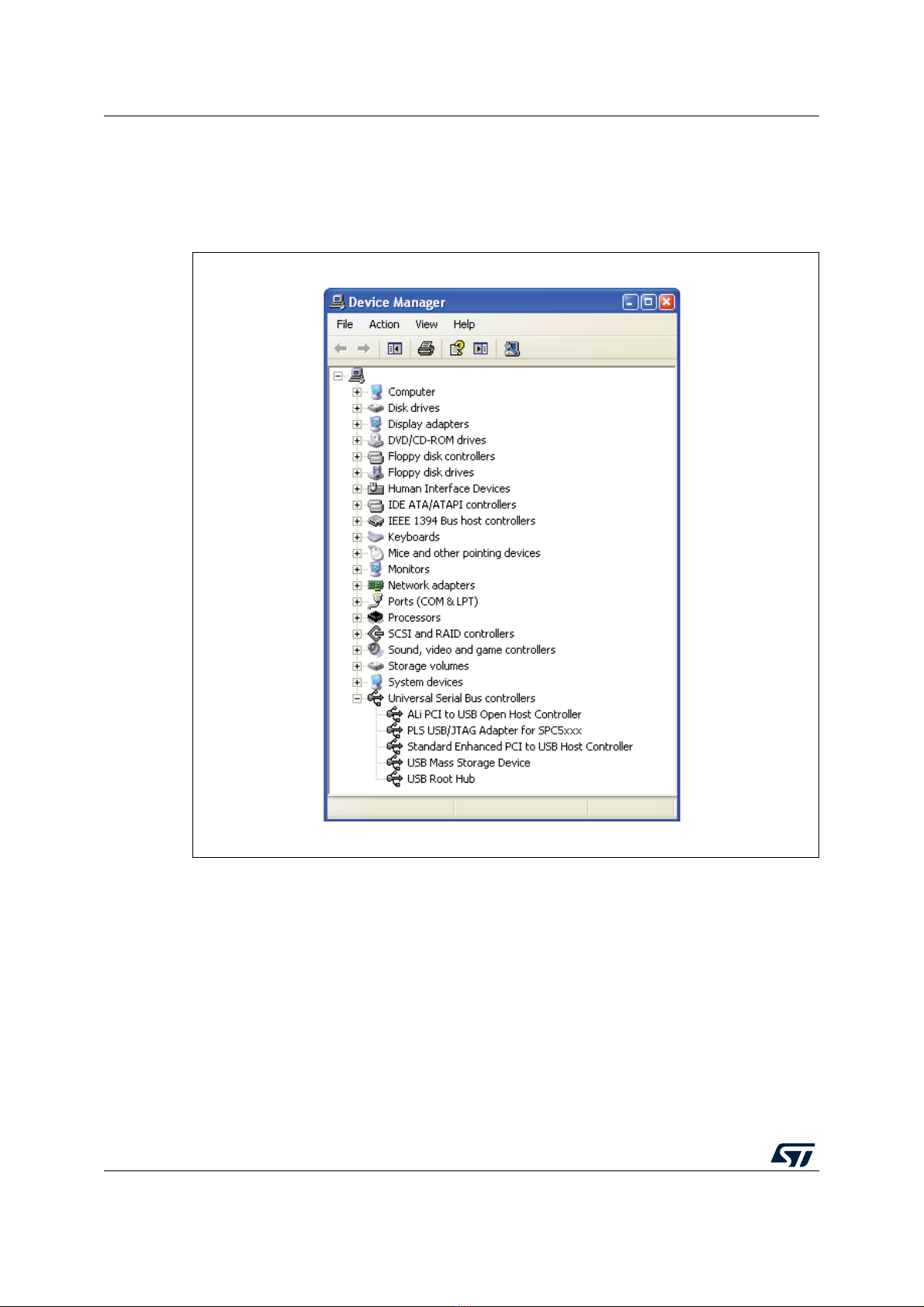
2.6.2 Driver installation of PLS USB/JTAG adapter for SPC5
If the previous steps are done successfully, the SPC5-UDESTK starter kit version installed
the hardware driver components automatically, when the SPC5-UDESTK PLS USB/JTAG
adapter for SPC5 is connecting to the host PC via the mini-USB cable the first time.