ST ST72F651 User manual

September 2007 Rev 1 1/30
UM0452
User manual
Temperature sensor evaluation board
Introduction
This document explains the functioning of the temperature sensor evaluation board which
consists of the ST72F651 microcontroller, STLM75 and STDS75 as temperature sensors,
and NAND Flash.
This board can operate in 2 modes:
■Standalone / external power mode
■USB powered mode
The configuration and operation of the evaluation board in both modes is explained in
different sections.
To select the desired mode, there is a power selection switch (S1) on the board which
enables the appropriate selection.
When this evaluation board is connected to the computer through a USB cable it also
functions as a mass storage device. The default state of the evaluation board is mass
storage mode. It switches over to temperature sensor mode using GUI.
Figure 1. Temperature sensor evaluation board (STEVAL-IFS003V1)
www.st.com

Contents UM0452
2/30
Contents
1 Abbreviations . . . . . . . . . . . . . . . . . . . . . . . . . . . . . . . . . . . . . . . . . . . . . . 5
2 Getting started . . . . . . . . . . . . . . . . . . . . . . . . . . . . . . . . . . . . . . . . . . . . . . 5
2.1 Package contents . . . . . . . . . . . . . . . . . . . . . . . . . . . . . . . . . . . . . . . . . . . . 5
2.2 Hardware description . . . . . . . . . . . . . . . . . . . . . . . . . . . . . . . . . . . . . . . . . 6
2.2.1 Components . . . . . . . . . . . . . . . . . . . . . . . . . . . . . . . . . . . . . . . . . . . . . . 6
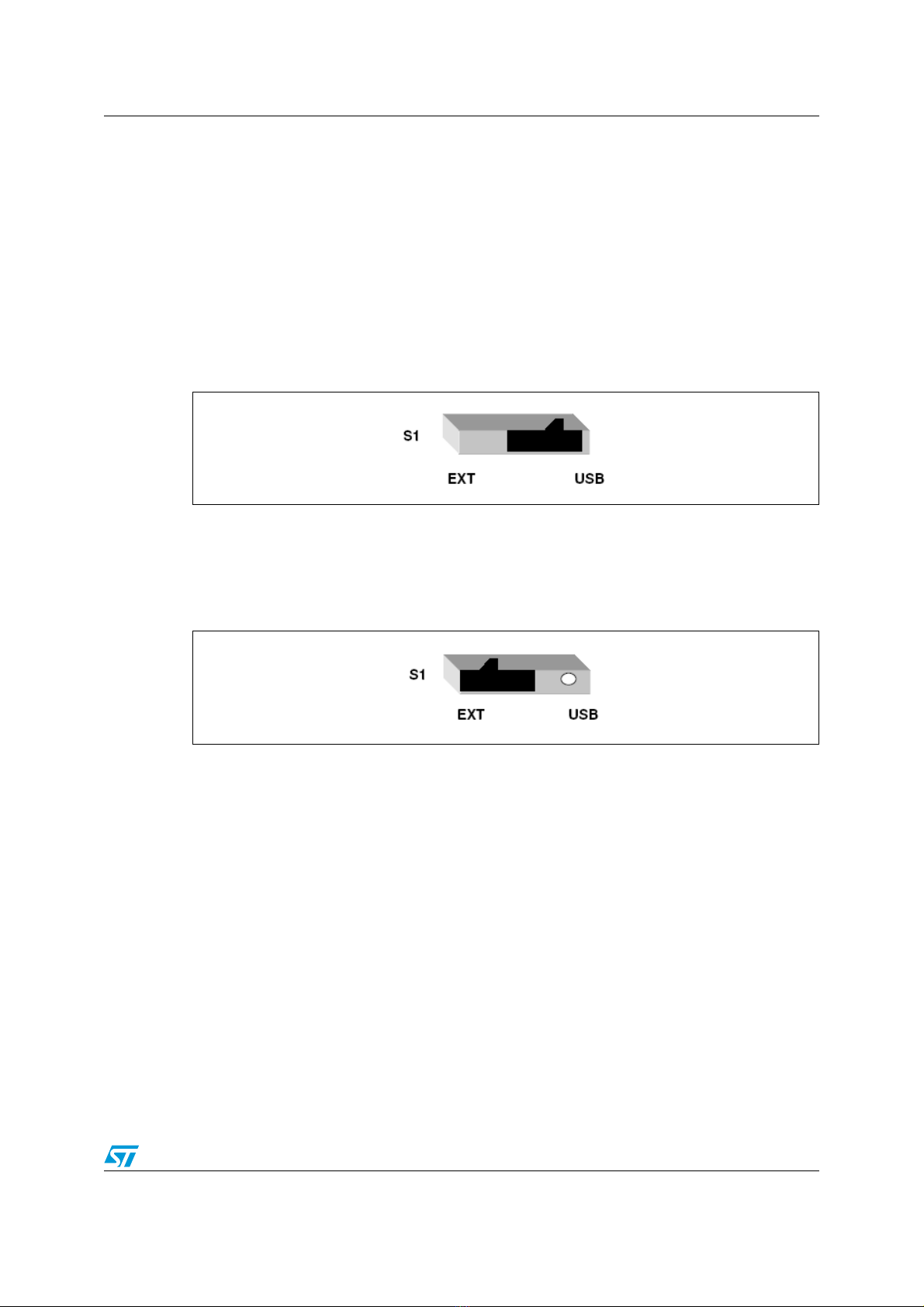
2.2.2 Power supply selection . . . . . . . . . . . . . . . . . . . . . . . . . . . . . . . . . . . . . . 7
3 External power mode of evaluation board . . . . . . . . . . . . . . . . . . . . . . . 8
3.1 Powering of evaluation board . . . . . . . . . . . . . . . . . . . . . . . . . . . . . . . . . . . 8
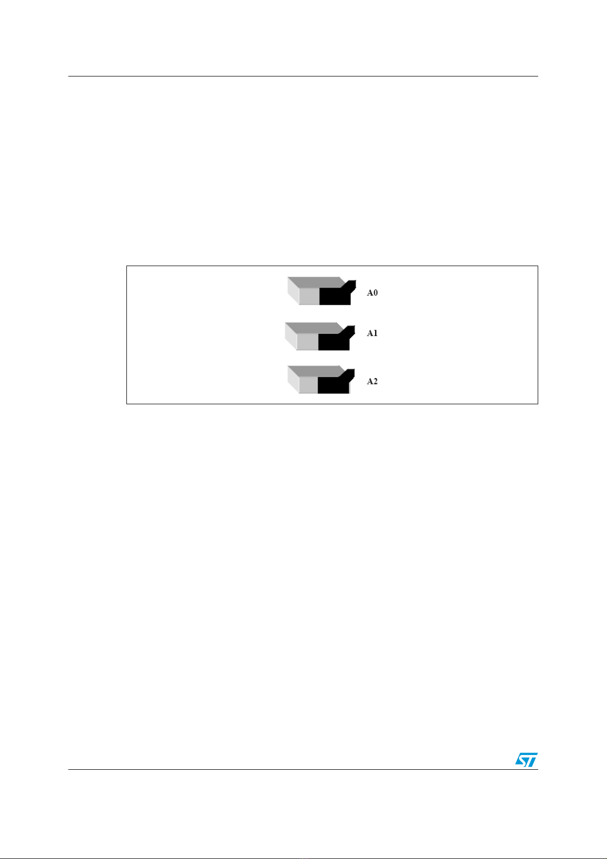
3.2 Address selection on the evaluation board . . . . . . . . . . . . . . . . . . . . . . . . . 8
3.2.1 Address configuration of TS1 using the switches . . . . . . . . . . . . . . . . . . 9
3.2.2 Address configuration of TS2 using the switches . . . . . . . . . . . . . . . . . 10
3.3 Values of temperature sensor registers in standalone mode . . . . . . . . . . 11
3.4 Behavior of FAN in standalone mode . . . . . . . . . . . . . . . . . . . . . . . . . . . . 11
3.5 Sequence of operation of evaluation board in standalone mode . . . . . . . 12
4 USB power/GUI mode of evaluation board . . . . . . . . . . . . . . . . . . . . . . 12
4.1 Getting started . . . . . . . . . . . . . . . . . . . . . . . . . . . . . . . . . . . . . . . . . . . . . 12
4.2 Powering of board in GUI mode . . . . . . . . . . . . . . . . . . . . . . . . . . . . . . . . 13
4.3 Switching to temperature sensor mode . . . . . . . . . . . . . . . . . . . . . . . . . . 14
4.3.1 Address selection in GUI mode . . . . . . . . . . . . . . . . . . . . . . . . . . . . . . 15
4.3.2 Address selection for TS1 (SO-8 package) . . . . . . . . . . . . . . . . . . . . . . 15
4.3.3 Address selection for TS2 (TSSOP-8 package) . . . . . . . . . . . . . . . . . . 15
4.3.4 Temperature sensor application selection . . . . . . . . . . . . . . . . . . . . . . . 15
4.3.5 Address checking using GUI . . . . . . . . . . . . . . . . . . . . . . . . . . . . . . . . . 16
4.3.6 Setting of temperature sensor registers . . . . . . . . . . . . . . . . . . . . . . . . . 18
4.3.7 Alarms . . . . . . . . . . . . . . . . . . . . . . . . . . . . . . . . . . . . . . . . . . . . . . . . . . 19
4.4 RTC mode of GUI . . . . . . . . . . . . . . . . . . . . . . . . . . . . . . . . . . . . . . . . . . . 20
4.4.1 RTC date and time setting . . . . . . . . . . . . . . . . . . . . . . . . . . . . . . . . . . . 20
4.4.2 RTC alarm setting . . . . . . . . . . . . . . . . . . . . . . . . . . . . . . . . . . . . . . . . . 20
4.4.3 RTC SYNC . . . . . . . . . . . . . . . . . . . . . . . . . . . . . . . . . . . . . . . . . . . . . . . 21
4.5 Plotter mode . . . . . . . . . . . . . . . . . . . . . . . . . . . . . . . . . . . . . . . . . . . . . . . 21

UM0452 Contents
3/30
4.5.1 Dynamic mode . . . . . . . . . . . . . . . . . . . . . . . . . . . . . . . . . . . . . . . . . . . . 22
4.5.2 NAND mode . . . . . . . . . . . . . . . . . . . . . . . . . . . . . . . . . . . . . . . . . . . . . . 23
5 Behavior of LEDS and buzzer . . . . . . . . . . . . . . . . . . . . . . . . . . . . . . . . 24
5.1 Power status LEDs . . . . . . . . . . . . . . . . . . . . . . . . . . . . . . . . . . . . . . . . . . 24
5.2 Application LEDs . . . . . . . . . . . . . . . . . . . . . . . . . . . . . . . . . . . . . . . . . . . 25
5.3 Buzzer . . . . . . . . . . . . . . . . . . . . . . . . . . . . . . . . . . . . . . . . . . . . . . . . . . . 25
5.4 Evaluation board schematic . . . . . . . . . . . . . . . . . . . . . . . . . . . . . . . . . . . 26
5.5 Bill of material . . . . . . . . . . . . . . . . . . . . . . . . . . . . . . . . . . . . . . . . . . . . . . 27
6 Revision history . . . . . . . . . . . . . . . . . . . . . . . . . . . . . . . . . . . . . . . . . . . 29

List of figures UM0452
4/30
List of figures
Figure 1. Temperature sensor evaluation board (STEVAL-IFS003V1) . . . . . . . . . . . . . . . . . . . . . . . . 1
Figure 2. Temperature sensor evaluation board . . . . . . . . . . . . . . . . . . . . . . . . . . . . . . . . . . . . . . . . . 6
Figure 3. Power selection switch to select external power . . . . . . . . . . . . . . . . . . . . . . . . . . . . . . . . . 7
Figure 4. Power selection switch to select for USB power. . . . . . . . . . . . . . . . . . . . . . . . . . . . . . . . . . 7
Figure 5. Logical level and relative switch positions . . . . . . . . . . . . . . . . . . . . . . . . . . . . . . . . . . . . . . 8
Figure 6. Default settings of TS2 to select TS1 on board . . . . . . . . . . . . . . . . . . . . . . . . . . . . . . . . . . 9
Figure 7. Default settings of TS1 to select TS2 on board . . . . . . . . . . . . . . . . . . . . . . . . . . . . . . . . . 10
Figure 8. GUI on start up with board not connected . . . . . . . . . . . . . . . . . . . . . . . . . . . . . . . . . . . . . 13
Figure 9. Board connected to GUI and status changed to connected in status bar. . . . . . . . . . . . . . 14
Figure 10. Temperature sensor mode selected . . . . . . . . . . . . . . . . . . . . . . . . . . . . . . . . . . . . . . . . . . 14
Figure 11. Temperature sensor window . . . . . . . . . . . . . . . . . . . . . . . . . . . . . . . . . . . . . . . . . . . . . . . 16
Figure 12. Address error message display on GUI . . . . . . . . . . . . . . . . . . . . . . . . . . . . . . . . . . . . . . . 17
Figure 13. Active temperature sensor window . . . . . . . . . . . . . . . . . . . . . . . . . . . . . . . . . . . . . . . . . . . 17
Figure 14. Temperature sensor register settings . . . . . . . . . . . . . . . . . . . . . . . . . . . . . . . . . . . . . . . . 19
Figure 15. RTC window . . . . . . . . . . . . . . . . . . . . . . . . . . . . . . . . . . . . . . . . . . . . . . . . . . . . . . . . . . . . 21
Figure 16. Plotter window for dynamic mode . . . . . . . . . . . . . . . . . . . . . . . . . . . . . . . . . . . . . . . . . . . . 22
Figure 17. Plotter window with dynamic mode graph . . . . . . . . . . . . . . . . . . . . . . . . . . . . . . . . . . . . . 23
Figure 18. Plotter window with NAND mode . . . . . . . . . . . . . . . . . . . . . . . . . . . . . . . . . . . . . . . . . . . . 24
Figure 19. Schematic . . . . . . . . . . . . . . . . . . . . . . . . . . . . . . . . . . . . . . . . . . . . . . . . . . . . . . . . . . . . . . 26

UM0452 Abbreviations
5/30
1 Abbreviations
2 Getting started
2.1 Package contents
The temperature sensor evaluation board includes the following items:
●Hardware content
– One evaluation board.
●Documentation
–Usermanual
●GUI installation file
Table 1. Abbreviations
Word Abbreviation
BLDC Fan Brushless direct current fan
GUI Graphical User Interface
LCD Liquid crystal display
USB Universal serial bus
RTC Real time clock
°C Degree Centigrade

Getting started UM0452
6/30
2.2 Hardware description
Figure 2. Temperature sensor evaluation board
2.2.1 Components
Major blocks present on the board are:
●Temperature sensor SO-8 package: STDS75M2F/STLM75M2F
●Temperature sensor TSSOP-8 package: STDS75DS2F/STLM75DS2F
●Microcontroller : ST72F651AR6T1
●NAND Flash : NAND512W3A0AN6
●BLDC FAN: 5 V
●RTC: M41T81S
●Graphic LCD (122 X 32)
●Button battery: 3 V
●AC buzzer
●Power socket for external power supply
●USB jacket for USB connection
●Switches TS1 and TS2 to configure the address of the temperature sensor
●Power selection switch (S1) to select between external power and USB power

UM0452 Getting started
7/30
2.2.2 Power supply selection
The board can work in two different power supply modes.
1. External power mode
2. USB powered mode
Selection of required power mode is done by the S1 switch.
1. External power mode selection:
To select for external supply mode place the switch as shown in Figure 3. Then plug in the
12 V adapter with a female connector to the power jacket (J1) and the green LED (EXT)
lights up.
Figure 3. Power selection switch to select external power
2. USB powered mode selection:
To select for USB powered mode plug out the external power supply and then turn the
power switch as shown in Figure 4. Then plug in the USB cable in the USB socket (J2) on
the board. The red LED (USB) lights and board will be powered up with USB power.
Figure 4. Power selection switch to select for USB power
Note: Only one power supply should be plugged in at once. The power LED ( green for external
supply and red for USB supply) lights up as soon as the power is plugged in, but power is
connected to the board only by the appropriate switch settings as shown in Figure 3 and
Figure 4.

External power mode of evaluation board UM0452
8/30
3 External power mode of evaluation board
This mode is also called standalone mode of the evaluation board. In this mode the board is
supplied by an external power supply and continuously displays the time and temperature
on LCD. We do not need any computer interface for this mode.
3.1 Powering of evaluation board
To power up the board, follow these steps:
1. Select the power selection switch (S1) to external power mode as explained above.
2. Plug in the DC power supply through adapter (7.5 V - 19 V output). As soon as power is
plugged in, the green LED (EXT) lights up.
Note: This LED (EXT) shows only that power is connected or not. Power to board is selected
through the power selection switch (S1).
3.2 Address selection on the evaluation board
There are a total of 6 address switches on the board: three for temperature sensor 1 (TS1)
and the other three for temperature sensor 2 (TS2).
Switches A0, A1, A2 are used for configuring the address lines of the temperature sensor 1
and A0#, A1#, A2# are used for configuring the address lines of temperature sensor 2.
Logic level is assigned to the address line using the address selection switches. Figure 5
shows the position of the switch and the respective logic level assigned by that switch.
Note: Address 0x9E is used for selecting the temperature sensor package on the board.
If TS1 = 0x9E then TS2 is selected for temperature measurement and if TS2 = 0x9E then
TS1 is selected for the temperature measurement.
Figure 5. Logical level and relative switch positions

UM0452 External power mode of evaluation board
9/30
3.2.1 Address configuration of TS1 using the switches
To select the temperature sensor 1 (TS1) follow these steps:
1. Put all the switches of TS2 (A0#, A1#, A2#), to logic level 1.Condition shown in
Figure 6.
Figure 6. Default settings of TS2 to select TS1 on board
2. Configure the addresses of temperature sensor 1 (TS1) using the switches. In
standalone mode seven addresses are allowed for TS1. These addresses are 0x90,
0x92, 0x94, 0x96, 0x98, 0x9A, 0x9C.
3. The allowed addresses and their settings for TS1 are as follows:
– Address 1 = 0x90, => A2 = 0, A1 = 0, A0 = 0
– Address 2 = 0x92, => A2 = 0, A1 = 0, A0 = 1
– Address 3 = 0x94, => A2 = 0, A1 = 1, A0 = 0
– Address 4 = 0x96, => A2 = 0, A1 = 1, A0 = 1
– Address 5 = 0x98, => A2 = 1, A1= 0, A0 = 0
– Address 6 = 0x9A, => A2 = 1, A1 = 0, A0 = 1
– Address 7 = 0x9C, => A2 = 1, A1 = 1, A0 = 0
Table 2. Switch settings for selecting a different address of TS1 on board
Address
lines
Address 1
0x90
Address 2
0x92
Address 3
0x94
Address 4
0x96
Address 5
0x98
Address 6
0x9A
Address 7
0x9C
A0
A1
A2

External power mode of evaluation board UM0452
10/30
After setting the address press the reset button (S2) present on the board.
The board then functions showing the temperature and time on LCD.
Note: If the address setting for TS1 is other than as shown in Ta bl e 2 or if the switches of TS2 are
not all set to 1 (as shown in Figure 6) then an error message appears on the LCD
"ADDR.ERROR" in which case, reconfigure the correct address of TS1 and again press the
reset button (S2).
3.2.2 Address configuration of TS2 using the switches
To select the temperature sensor 2 (TS2) follow these steps:
1. Put all switches of TS1 (A0, A1, A2) to logic level 1 as shown in Figure 7.
Figure 7. Default settings of TS1 to select TS2 on board
2. Configure the addresses of temperature sensor 2 (TS2) using the switches. In
standalone mode seven addresses are allowed for TS2.
These addresses are: 0x90,0x92,0x94,0x96,0x98, 0x9A and 0x9C.
The allowed addresses and their settings for TS2 are as follows:
●Address 1 = 0x90, => A2# = 0, A1# = 0, A0#= 0
●Address 2 = 0x92, => A2#= 0, A1# = 0, A0# = 1
●Address 3 = 0x94, => A23 = 0, A1# = 1, A0# = 0
●Address 4 = 0x96, => A2#= 0, A1# = 1, A0# = 1
●Address 5 = 0x98, => A2# = 1, A1# = 0, A0# = 0
●Address 6 = 0x9A, => A2# = 1, A1# = 0, A0# = 1
●Address 7 = 0x9C, => A2# = 1, A1# = 1, A0# = 0

UM0452 External power mode of evaluation board
11/30
3. After setting the address press the reset button (S2) present on the board.
4. Then the board functions showing the temperature and time on LCD.
Note: If the address setting for TS2 is other than as shown in Ta bl e 3 or if the switches of TS1 are
not all set to 1 (Figure 7) then an error message appears on the LCD "ADDR.ERROR", in
which case, reconfigure the correct address of TS1 and again press the reset button (S2).
Note: If the addresses are configured and there is no device in the socket an error message is
displayed on the LCD as "DEVICE ERR”, in which case place the device in the socket, and
reconfigure the addresses to select the device. Press the reset button to start the
application.
3.3 Values of temperature sensor registers in standalone mode
3.4 Behavior of FAN in standalone mode
There is a 5 V BLDC FAN present on the board. Whenever the temperature measured by
the sensor rises above the Tos (29 degree C in standalone case) value the FAN starts
running. As the measured temperature increases, the speed of FAN also increases until the
temperature reaches the maximum value setting (40 degree C for standalone case). For
temperature greater than 40 degree C, the FAN runs at maximum speed.
For the time and date an RTC is present on the board. This RTC also has a 3 V button
battery (Maxell CR2032) which powers the RTC in absence of power. Once the time and
Table 3. Switch settings for selecting a different address of TS2 on board
Address
lines
Address 1
0x90
Address 2
0x92
Address 3
0x94
Address 4
0x96
Address 5
0x98
Address 6
0x9A
Address 7
0x9C
A0#
A1#
A2#
Table 4. Register values in standalone mode
Register name Value
Oversaturation (Tos) 29 Degree centigrade
Hysteresis (Thys) 27 Degree centigrade
Configuration (Tconfig) 0x04

USB power/GUI mode of evaluation board UM0452
12/30
date are configured in the RTC using GUI, the RTC keeps the time and date record. This
time and date is displayed on the LCD at each powering sequence.
3.5 Sequence of operation of evaluation board in standalone
mode
To use the board in standalone mode follow these steps:
●Place the temperature sensor in socket 1 (TS1) or socket 2 (TS2).
●Configure the address lines of TS1 and TS2 accordingly.
●Adjust the power selection switch (S1) to select the external power supply.
●Plug in the power adapter to the board and switch on the supply.
●Press the reset button (S2) on the board.
●The application starts running. Temperature and time are displayed on the LCD.
Note: If the address configuration is not done as mentioned in Section 3.2,an ADDR.ERROR
message on the LCD appears, in which case, reconfigure the board for the correct address
and then press the reset button (S2).
If the addresses are correctly configured but there is no device in the socket, an error
message on the LCD appears as "DEVICE ERR.", in which case, place the device in the
socket, configure the address lines and then press the reset button to start the application.
4 USB power/GUI mode of evaluation board
The second mode of operation of the Temperature sensor board uses GUI through a USB
connection. In this mode if GUI is not connected, then the board functions as a mass
storage device and appears as a removable drive on computer. To use the board in
temperature sensor mode we connect it to the computer using the USB cable and
communicate with GUI using the USB communication protocol. GUI is used to configure the
temperature sensor registers and to explore all the features of the temperature sensor.
4.1 Getting started
Run the GUI setup (.exe) file to install GUI on the host system.
To install the GUI, the user should have administrative rights, as the setup overwrites files
(.dll) in the system folder that are protected using administrative rights. If the user does not
have administrative rights, this GUI cannot be installed (error message: 0x80040707
appears). Open up the temperature sensor GUI by clicking on the GUI icon which opens the
GUI window as shown in Figure 8.

UM0452 USB power/GUI mode of evaluation board
13/30
Figure 8. GUI on start up with board not connected
4.2 Powering of board in GUI mode
Follow these steps in order to power the board in GUI mode:
1. Adjust the power selection switch (S1) to select USB power mode as explained in
Figure 4.
2. Plug the USB cable in the USB socket (J2) on the board. As soon as the USB cable is
plugged in, the red LED lights up.
Note: This LED (USB) shows only that power is connected or not. Power to board is selected
through the power selection switch (S1).
3. After plugging in the USB cable and if the power switch is correctly set, then the status
in the status bar of GUI changes to "Connected" as shown in Figure 9.

USB power/GUI mode of evaluation board UM0452
14/30
Figure 9. Board connected to GUI and status changed to connected in status bar
4.3 Switching to temperature sensor mode
By default the board is in mass storage mode and as we open the GUI it shows the Mass
storage mode in status bar. Once the board is connected to GUI and the status changes to
connected in status bar, press the temperature sensor mode selection button in the toolbar
to switch to temperature sensor mode. As the GUI goes in temperature sensor mode, all
three icons of temperature sensor, clock and plotter become active. GUI appears as shown
in Figure 10.
Figure 10. Temperature sensor mode selected

UM0452 USB power/GUI mode of evaluation board
15/30
In this mode the LCD shows:
●Temperature written in Chinese and °C in first row
●Date and time in second row
4.3.1 Address selection in GUI mode
In GUI mode we can address two different packages of temperature sensors: TS1 is the SO-
8 package of STDS75/STLM75 and TS2 is the TSSOP-8 package of STDS75/STLM75.
Each of the sensor packages can have eight different addresses but in order to access both
sensors using GUI, one address is fixed for package selection and the remaining seven
addresses can be configured for the sensor.
Note: The address 0x9E is fixed for package selection. If a user wants to select TS1 for
application, the address of TS2 should be 0x9E. The user can then give any of the
remaining seven addresses (0x90, 0x92, 0x94, 0x96, 0x98, 0x9A, 0x9C) to sensor 1 using
the TS1 switches on the board.
4.3.2 Address selection for TS1 (SO-8 package)
To select the TS1 package temperature sensor, follow these steps:
1. Put all switches of TS2 (A0#, A1#, A2#) to logic high, that is, assign address 0x9E to
TS2.
2. Then using the TS1 switches assign any of the remaining 7 addresses to the TS1
sensor. Possible addresses for TS1 are 0x90, 0x92, 0x94, 0x96, 0x98, 0x9A, 0x9C.
4.3.3 Address selection for TS2 (TSSOP-8 package)
To select TS2 package temperature sensor, follow the following steps:
1. Put all the switches of TS1 (A0, A1, A2) to logic high, that is. assign address 0x9E to
TS1.
2. Then using the TS2 switches assign any of the remaining 7 addresses to the TS2
sensor. Possible addresses for TS2 are 0x90, 0x92, 0x94, 0x96, 0x98, 0x9A, 0x9C.
Note: If in error the address selection on both the switches is 0x9E , then "ADDR ERROR"
appears on the LCD.
4.3.4 Temperature sensor application selection
1. To start the temperature sensor application click on the temperature sensor icon in the
toolbar. It opens the temperature sensor window as shown in Figure 11.
2. Select one temperature sensor either STLM75 or STDS75.
3. Select the address from the Choose Address drop down menu on GUI. Select the
address on the board using the address selection switches.

USB power/GUI mode of evaluation board UM0452
16/30
Figure 11. Temperature sensor window
4.3.5 Address checking using GUI
After the sensor package is selected and address is selected on the board (as stated in
Section 4.3.1), the address is sent from the GUI through the drop down menu of Choose
Address. If the address sent by the GUI does not match the address setting done on the
board, an error message pops up on GUI as shown in Figure 12, in which case, check the
address setting on the board and the address sent by GUI. Reset the address and then
recheck the address. When the addresses match, the temperature sensor window becomes
active and the default settings of the sensor registers are displayed on GUI as shown in
Figure 13.

UM0452 USB power/GUI mode of evaluation board
17/30
Figure 12. Address error message display on GUI
Figure 13. Active temperature sensor window

USB power/GUI mode of evaluation board UM0452
18/30
4.3.6 Setting of temperature sensor registers
There are four different registers in the temperature sensor which can be configured. The
behavior of the sensor depends on this configuration. These registers are:
1. 8 bit Configuration register
2. 16 bit Oversaturation (Tos) register
3. 16 bit Hysteresis (Thys) register
4. 16 bit read only temperature register
GUI has a register section to configure the following registers.
1. Configuration register:
– GUI has a drop down menu to set up the configuration register. Select the desired
bits in the configuration register.
– Press the WRITE button to program the sensor with the selected value
–Figure 14 shows the settings
2. Oversaturation register (Tos):
– This register is used to enter the oversaturation temperature
– Enter the desired temperature using the slider or through the up /down button
– Press the WRITE button to program the sensor with the selected temperature
–Figure 14 shows the settings
3. Hystersis register (Thys):
– This register is used to enter the hysteresis temperature
– Enter the desired hysteresis temperature using the slider or the up/down button
– Press the WRITE button to program the sensor with this value of hysteresis.
–Figure 14 shows the settings
Table 5. Switch configuration for different address settings
Address
lines
Address 1
0x90
Address 2
0x92
Address 3
0x94
Address 4
0x96
Address 5
0x98
Address 6
0x9A
Address 7
0x9C
A0
A1
A2

UM0452 USB power/GUI mode of evaluation board
19/30
4. Temperature register:
– This register is used to show the temperature measured by the sensor.
– The ONCE button is used to read the temperature at any one instant.
– The LOOP button is used to continuously measure and display the temperature.
– Alarms appear on GUI only when the GUI is in LOOP mode.
The first slider present on GUI is the maxima temperature for FAN. This is used for setting
the temperature after which the FAN runs at maximum speed. To reset this temperature
adjust the slider and set the value by pressing the WRITE button.
The READ button is used for reading the values back from the sensor present on the board.
As soon as the address is checked, the registers show the default settings in this window.
Note: Setting of temperature values uses the following order for the correct functionality of the
sensor: Maxima Temperature for FAN > Oversaturation Temperature > Hystersis
Temperature
GUI does not allow violating the above condition.
Figure 14. Temperature sensor register settings
4.3.7 Alarms
To see the state of the alarms, the GUI should be in loop mode for continuous reading of the
temperature. There are three alarms present on the GUI:
1. Temperature alarm:
Whenever the temperature measured by GUI rises above the temperature set for maxima
temperature for FAN this alarm lights up. When the Temperature falls below "Maxima
Temperature for FAN" the alarm goes off.
2. Oversaturation alarm:

USB power/GUI mode of evaluation board UM0452
20/30
This alarm is used to indicate the behavior of the OS pin output of the temperature sensor.
Its nature is dependent on the polarity selected in the configuration register.
– If the polarity selected in the configuration register is LOW then:
a) Default state: alarm LIGHTS UP
b) Temperature rises above oversaturation temperature (Tos): alarm goes off
c) Temperature falls below Thys: alarm LIGHTS UP
– If the polarity selected in the configuration register is HIGH, then:
a) Default state: alarm off
b) Temperature rises above Tos: alarm LIGHTS UP
c) Temperature falls below Thys: alarm off
3. FAN alarm:
This alarm demonstrates the behavior of the FAN present on the board.
a) Default state: alarm off
b) FAN starts running (for T >= Tos): alarm turns YELLOW
c) FAN starts running at full speed (for T >= Tmax for FAN): alarm turns RED
4.4 RTC mode of GUI
4.4.1 RTC date and time setting
1. Click on the CLOCK icon in the toolbar of GUI. The RTC window opens up as shown in
Figure 14.
2. The user can configure the RTC DATE and TIME by clicking on the date and time panel
of RTC.
3. Press the WRITE button to enter these new values in the RTC present on the board.
4. Press the READ button which shows the clock after reading the RTC from the board
4.4.2 RTC alarm setting
1. Set the alarm date and time using the alarm panel of the RTC GUI window
2. Press the WRITE button to enter these alarm settings in the RTC present on the board
3. When the alarm date and time match, the alarm signal turns RED on the GUI.
4. To reset the alarm signal, rewrite either the RTC date and time or alarm settings.
This manual suits for next models
1
Table of contents
Other ST Motherboard manuals

ST
ST STEVAL-BLUEMIC-1 User manual

ST
ST EVAL-IBD002-35W User manual

ST
ST EVALKITSTKNX User manual

ST
ST STM8/128-EVAL User manual

ST
ST STEVAL-ISC004V1 User manual

ST
ST FDA803S User manual

ST
ST AN3954 Installation and operating instructions

ST
ST STEVAL-IPC002V1 User manual

ST
ST STM32CubeH7 User manual

ST
ST EVSPIN32G4-DUAL User manual

ST
ST STM3210C-EVAL User manual

ST
ST STEVAL-OET001V1 User manual

ST
ST X-NUCLEO-NFC03A1 User manual

ST
ST STEVAL-LVLP01 User manual

ST
ST STM32MP157 Series User manual

ST
ST SPC58XXADPT292S User manual

ST
ST STM3221G-EVAL User manual

ST
ST STM32G474E-EVAL User manual

ST
ST MB1367 User manual

ST
ST STEVAL-ISF003V1 User manual