ST TN100 RF User manual

January 2009 Rev 1 1/37
UM0579
User manual
TN100 RF evaluation kit
This document describes the TN100 RF evaluation kit (TN100/M32B-EVAL) used to
evaluate the capabilities of the TN100 device for ranging operations and RF data
transmission based on the Chirp technology.
The entire package consists of two TN100 sensor boards (version 1.1) and a complete
software package.
Both boards are exactly the same and are equipped with:
■a board (TN100-RCM) which integrates both an STM32 microcontroller and a TN100
transceiver
■a set of sensors to detect temperature and accelerations
■one reset (S1) and three general-purpose buttons (S2 to S4)
■four general-purpose LEDs (LD1 to LD4), Tx/Rx activity LED (LD5), power supply LED
(LD6)
The sensor boards act as source of information providing data regarding distance
measurement (ranging), temperature, accelerations, and status.
The software consists of:
■The ST TN100 Application running on a host PC used to interact with the sensor boards
and easily perform ranging operations, packet data transmission, and retrieval of on-
board sensor data. Additionally, it offers a graphical representation of the two-node
network constituted by the sensor boards.
■Firmware running on the STM32 microcontroller including: driver for the TN100 device,
drivers for all the sensors such as MEMS, temperature, internal protocol used to
exchange data, and commands, among nodes and the PC.
More details on boards and software are provided in the following sections.
Figure 1. TN100 sensor board with STM32 microcontroller
www.st.com
Obsolete Product(s) - Obsolete Product(s)

Obsolete Product(s) - Obsolete Product(s)
Contents UM0579
2/37
Contents
1 Reference information . . . . . . . . . . . . . . . . . . . . . . . . . . . . . . . . . . . . . . . 4
1.1 Acronyms and definitions . . . . . . . . . . . . . . . . . . . . . . . . . . . . . . . . . . . . . . 4
1.2 References . . . . . . . . . . . . . . . . . . . . . . . . . . . . . . . . . . . . . . . . . . . . . . . . . 4
2 Description of the delivered package . . . . . . . . . . . . . . . . . . . . . . . . . . . 5
2.1 Hardware overview . . . . . . . . . . . . . . . . . . . . . . . . . . . . . . . . . . . . . . . . . . . 5
2.2 Software overview . . . . . . . . . . . . . . . . . . . . . . . . . . . . . . . . . . . . . . . . . . . 6
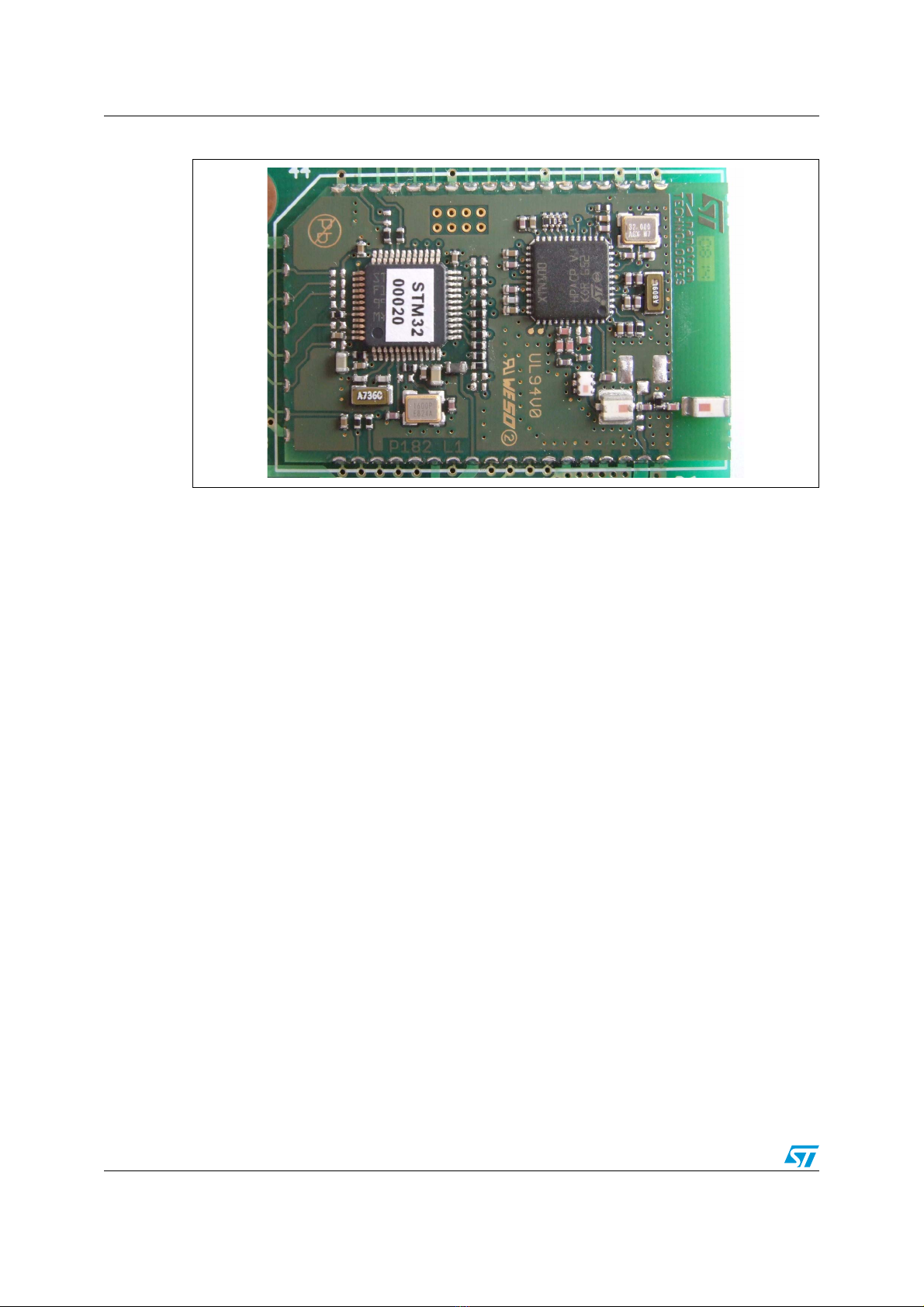
3 TN100 sensor board . . . . . . . . . . . . . . . . . . . . . . . . . . . . . . . . . . . . . . . . . 8
3.1 Description of connectors . . . . . . . . . . . . . . . . . . . . . . . . . . . . . . . . . . . . . . 9
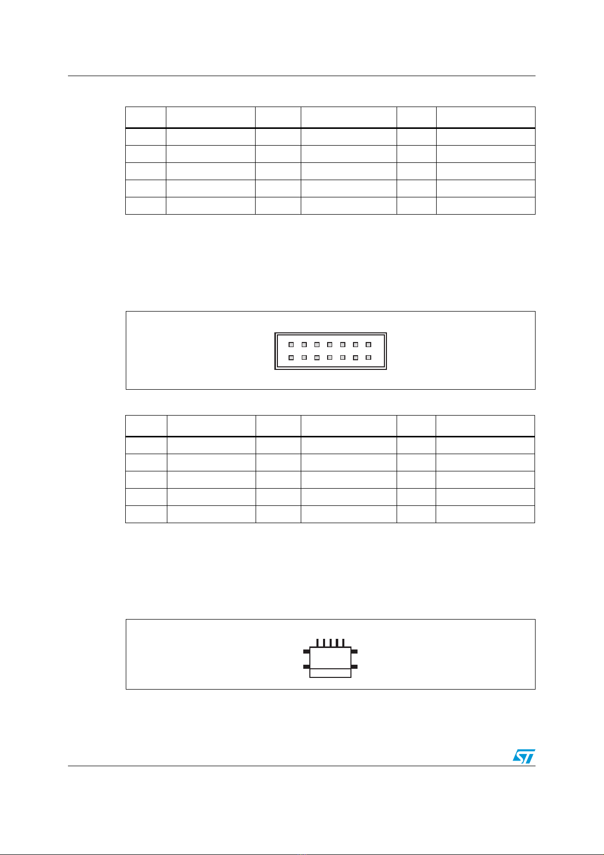
3.1.1 JTAG connector (CN1) . . . . . . . . . . . . . . . . . . . . . . . . . . . . . . . . . . . . . . . 9
3.1.2 Extension connector (CN2) . . . . . . . . . . . . . . . . . . . . . . . . . . . . . . . . . . . 9
3.1.3 Extension connector (CN3) . . . . . . . . . . . . . . . . . . . . . . . . . . . . . . . . . . 10
3.1.4 USB connector (CN4) . . . . . . . . . . . . . . . . . . . . . . . . . . . . . . . . . . . . . . 10
3.1.5 RS-232 connector (CN5) . . . . . . . . . . . . . . . . . . . . . . . . . . . . . . . . . . . . 11
3.2 General-purpose and reset buttons . . . . . . . . . . . . . . . . . . . . . . . . . . . . . 12
3.3 LED indicators . . . . . . . . . . . . . . . . . . . . . . . . . . . . . . . . . . . . . . . . . . . . . 13
3.4 Power supply . . . . . . . . . . . . . . . . . . . . . . . . . . . . . . . . . . . . . . . . . . . . . . 14
4 Getting started . . . . . . . . . . . . . . . . . . . . . . . . . . . . . . . . . . . . . . . . . . . . . 16
4.1 Kit setup . . . . . . . . . . . . . . . . . . . . . . . . . . . . . . . . . . . . . . . . . . . . . . . . . . 16
4.1.1 Software installation . . . . . . . . . . . . . . . . . . . . . . . . . . . . . . . . . . . . . . . . 16
4.1.2 Board setup . . . . . . . . . . . . . . . . . . . . . . . . . . . . . . . . . . . . . . . . . . . . . . 16
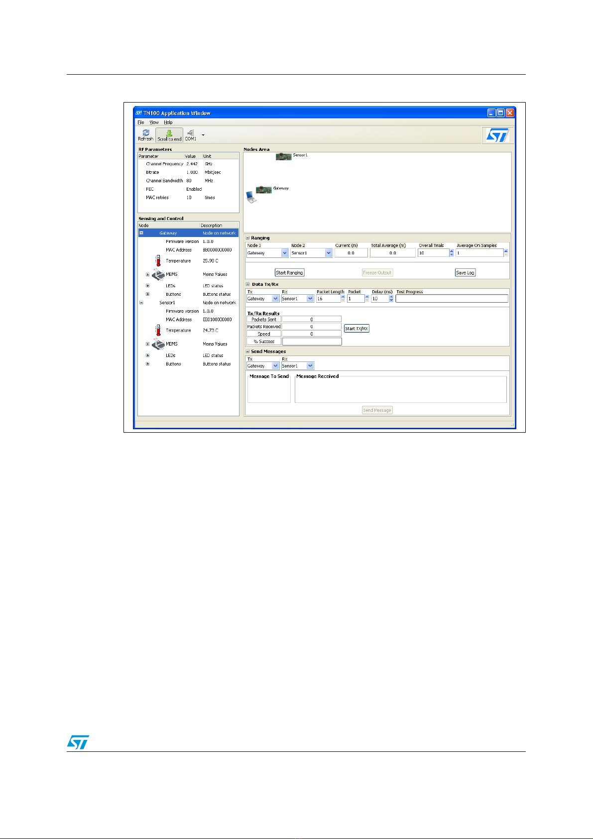
4.2 Application description . . . . . . . . . . . . . . . . . . . . . . . . . . . . . . . . . . . . . . . 17
4.2.1 Running the application . . . . . . . . . . . . . . . . . . . . . . . . . . . . . . . . . . . . . 17
4.2.2 Menu bar and toolbar . . . . . . . . . . . . . . . . . . . . . . . . . . . . . . . . . . . . . . . 17
4.2.3 Sensing and control . . . . . . . . . . . . . . . . . . . . . . . . . . . . . . . . . . . . . . . . 18
4.2.4 Ranging . . . . . . . . . . . . . . . . . . . . . . . . . . . . . . . . . . . . . . . . . . . . . . . . . 19
4.2.5 Data Tx/Rx . . . . . . . . . . . . . . . . . . . . . . . . . . . . . . . . . . . . . . . . . . . . . . . 21
4.2.6 Send messages . . . . . . . . . . . . . . . . . . . . . . . . . . . . . . . . . . . . . . . . . . . 22
4.2.7 RF parameters . . . . . . . . . . . . . . . . . . . . . . . . . . . . . . . . . . . . . . . . . . . . 22
4.2.8 Packet log . . . . . . . . . . . . . . . . . . . . . . . . . . . . . . . . . . . . . . . . . . . . . . . 23
5 Updating firmware nodes . . . . . . . . . . . . . . . . . . . . . . . . . . . . . . . . . . . . 24

Obsolete Product(s) - Obsolete Product(s)
UM0579 Contents
3/37
5.1 Upload firmware using HyperTerminal . . . . . . . . . . . . . . . . . . . . . . . . . . . 24
5.2 Upload firmware using TN100 application . . . . . . . . . . . . . . . . . . . . . . . . 25
5.3 Loading the boot loader into the sensor board . . . . . . . . . . . . . . . . . . . . . 26
Appendix A Board assembly setup manual . . . . . . . . . . . . . . . . . . . . . . . . . . . . . 27
Appendix B Bill of materials . . . . . . . . . . . . . . . . . . . . . . . . . . . . . . . . . . . . . . . . . 29
Appendix C Artwork prints . . . . . . . . . . . . . . . . . . . . . . . . . . . . . . . . . . . . . . . . . . 31
Appendix D Schematic diagrams . . . . . . . . . . . . . . . . . . . . . . . . . . . . . . . . . . . . . 33
Revision history . . . . . . . . . . . . . . . . . . . . . . . . . . . . . . . . . . . . . . . . . . . . . . . . . . . . 36

Obsolete Product(s) - Obsolete Product(s)
Reference information UM0579
4/37
1 Reference information
1.1 Acronyms and definitions
1.2 References
1. TN100 RF board datasheet
2. TN100 High performance CSS transceiver enabling location awareness datasheet
3. LIS302DL MEMS motion sensor 3-axis
4. STLM20W87F analog temperature sensor
5. STM32F103CB STM32 ARM-based 32-bit MCU
Please check the STMicroelectronics web site www.st.com for any available updates.
Table 1. List of acronyms and definitions
Term Meaning
ARQ The Automatic Repeat Request (ARQ) scheme is used to achieve correct
data transmission.
CSMA/CA Carrier Sense Multiple Access with Collision Avoidance
CSS Chirp Spread Spectrum
FEC
The Forward Error Correction coding scheme is a (7, 4) shortened
Hamming code and consists of 4 data bits and 3 parity bits. The FEC
scheme on the MACFrame reduces the number of retransmissions.
LBS Location-based services
MAC Medium Access Controller
MAC retries Maximum allowed number of retransmission attempts for Data packets.
Ranging Term used to indicate the capability to determine the distance between two
RF devices.
RTLS Real-time locating system
SPI Serial Peripheral Interface bus
TDMA Time Division Multiple Access

Obsolete Product(s) - Obsolete Product(s)
UM0579 Description of the delivered package
5/37
2 Description of the delivered package
The ST RF TN100 Evaluation kit contains the following items:
●One guarantee record card
●Two TN100 sensor boards
●One CD-ROM including the following items:
– Application and firmware source code
–Usermanual
– Board schematics
– Datasheets
Please check the STMicroelectronics website www.st.com for any available updates and
downloads.
2.1 Hardware overview
Figure 2 shows the main components of the sensor boards contained in the package.
The TN100 transceiver is a highly integrated mixed signal chip that uses CSS (chirp spread
spectrum) wireless communication technology. With its unique ranging capability, the TN100
can measure the link distance between two nodes. Thus, the TN100 supports location
awareness applications including location-based services (LBS) and asset tracking (2D/3D
RTLS). Ranging is performed during regular data communication and does not require
additional infrastructure, power, and/or bandwidth. The TN100 transceiver IC is designed to
build up robust, short distance wireless networks operating in the 2.45 GHz ISM band with
extremely low power consumption over a wide range of operating temperatures.
The TN100 supports 7-frequency channels with 3 non-overlapping channels. This provides
support for multiple physically independent networks and improved coexistence
performance with existing 2.4 GHz wireless technologies. Data rates are selectable between
2 Mbps and 125 kbps. The TN100 transceiver includes a sophisticated Medium Access
Controller (MAC) with CSMA/CA and TDMA support as well as forward error correction
(FEC) and 128-bit hardware encryption. Through its high-speed standard SPI interface, the
TN100 can be interfaced with an external microcontroller. It includes a 4-kbit frame buffer so
that several receive and transmit frames can be stored simultaneously in the buffers. This
solution eliminates the problems of different peak data rates between air and microcontroller
interfaces.
ST's STM32 family of 32-bit Flash microcontrollers is based on the breakthrough ARM
Cortex™-M3 core - a core specifically developed for embedded applications. The STM32
family benefits from the Cortex-M3 architectural enhancements including the Thumb®-2
instruction set to deliver improved performance with better code density, significantly faster
response to interrupts, all combined with industry leading power consumption.

Obsolete Product(s) - Obsolete Product(s)
Description of the delivered package UM0579
6/37
Figure 2. TN100 RF board
The smart TN100 RF board is only 39 mm by 24 mm and less than 3 mm thick. Yet, it
integrates all required components for a complete RF circuit based on the innovative
transceiver. As well as the chip, this board includes the ST STM32 microcontroller (MCU), a
band pass filter, a balun and an integrated 2.4 GHz chip antenna.
More details may be found in Section 3: TN100 sensor board.
2.2 Software overview
The ST TN100 Application is provided to evaluate the ST TN100 technology and hence
perform remote ranging operations between nodes, sending and receiving simple data
packets and text messages, getting sensor values, and setting the status of on-board LEDs.
The application's Graphical User Interface is designed for easy interaction with the sensor
boards thanks to an integrated environment where all the relevant parameters may be set
and monitored (see Figure 3: TN100 application window). Additionally, the user is also able
to hide and/or show certain features in order to focus on the more relevant data. The benefit
consists in being able to launch a single application and perform all possible actions using
the ST TN100 technology.
The application provides the user interface for both sensors boards.

Obsolete Product(s) - Obsolete Product(s)
UM0579 Description of the delivered package
7/37
Figure 3. TN100 application window
Basically, the application running on the PC cooperates with the firmware running on the
sensor nodes and it is able to:
●Get specific parameters such as MAC address, channel, FEC, MAC retries, and so on,
for each sensor node
●Get sensor data for each sensor including temperature, acceleration, buttons, LEDs
●Start & Stop packet and message transmissions, and ranging, between sensor nodes
●Set on-board LED status for each sensor node

Obsolete Product(s) - Obsolete Product(s)
TN100 sensor board UM0579
8/37
3 TN100 sensor board
The TN100 sensor board includes the TN100 high performance chirp spread spectrum
transceiver enabling location awareness using an STM32F103 Cortex™-M3 32-bit
microcontroller. It provides the following features:
●Sensors
– Temperature meter (U2)- STLM20 (analog)
– 3-axis accelerometer (U3) - LIS302DL (digital)
– Potentiometer (R10) (analog)
●RS-232 communication interface, DB9 D-sub connector
●Two 14-pin header connectors (CN2, CN3) for connecting different hooks on
extensions
●Power supply options: + 5 V from JTAG (J-Link), USB + 5 V VBUS, NiMH batteries.
On-board step-up converter and linear regulator (+ 2.5 V)
●One reset (S1) and three general-purpose buttons (S2 to S4)
●Four general-purpose LEDs (LD1 to LD4), TX/RX activity LED (LD5), power supply
LED (LD6)
●Many configuration options for sensors and peripherals
●20-pin JTAG connector (CN1) for debug purposes
Figure 4. TN100 sensor board block diagram
MEMS
14 pin headerRS-232
nanoLOC
TN100 module
with STM32
microcontroller
JTAG
Step-up
and
LDO
2.5 V
Buttons LEDs
14 pin header
USB Slide
switches
AM00269
Batteries
Barometer Potentiometer
Temperature
sensor
Reset
button
Ext.
antenna

Obsolete Product(s) - Obsolete Product(s)
UM0579 TN100 sensor board
9/37
3.1 Description of connectors
3.1.1 JTAG connector (CN1)
The 20-pin connector (CN1) provides the JTAG interface as shown in Figure 5. This
interface is primarily used for communicating with a PC using a suitable converter box such
as J-Link from IAR Systems™. There exists a wide choice of development tools on the
market supporting microcontroller Flash memory programming and application debugging.
Using the J-Link DBGACK pin, an external + 5 V power supply can be delivered to the board
as an optional supply voltage. (Verify which J-Link revision supports this feature at
http://www.segger.com).
Figure 5. JTAG connector pinout
3.1.2 Extension connector (CN2)
The 14-pin extension connector CN2 can be used together with the CN3 connector to
connect an extension. The CN2 to CN3 pitch distance is 2.54 mm so it makes it possible to
connect a standardized bread board or other extension.
Figure 6. Extension connector (CN2) pinout
Table 2. JTAG connector (CN1) pin description
Pin Signal Pin Signal Pin Signal Pin Signal
12.5VDC 6GND 11
JRTCK, connected to
GND by R10 (10 kΩ)16 GND
2 2.5 V DC 7 JTMS 12 GND 17 DBGRQ connected to
GND by R (10 kΩ)
3 JTRST 8 GND 13 JTDO 18 GND
4 GND 9 JTCK 14 GND 19
DBGACK connected to
GND by R (10kΩ), used
also as an external +5 V
power supply
5 JTDI 10 GND 15 NRST 20 GND
1
2
3579
46810
11 13 15 17 19
12 14 16 18 20
AM00262
1
2
3579
46810
11 13
12 14
AM00263

Obsolete Product(s) - Obsolete Product(s)
TN100 sensor board UM0579
10/37
3.1.3 Extension connector (CN3)
The 14-pin extension connector CN3 can be used together with the CN2 connector to
connect an extension. The CN2 to CN3 pitch distance is 2.54 mm so it makes it possible to
connect a standardized bread board or other extension.
Figure 7. Extension connector (CN3) pinout
3.1.4 USB connector (CN4)
The board includes a mini USB AB SMT connector. The communication lines are not used
with the TN100 board. The VBUS + 5 V voltage (pin 1) can be used as an alternative board
power supply.
Figure 8. USB connector (CN4) pinout
Table 3. Extension connector (CN2) pin description
Pin STM32 pin Pin STM32 pin Pin STM32 pin
1GND 6 PB8 11PA2
2 2.5 V DC 7 PB9 12 PA3
3 PB5 8 PC13 13 NC
4 PB6 9 PA0 14 NC
5 PB7 10 PA1
Table 4. Extension connector (CN3) pin description
Pin STM32 pin Pin STM32 pin Pin STM32 pin
1 GND 6 PB12 11 PA9
2 2.5 V DC 7 PB13 12 PA10
3 PB2 8 PB14 13 PA11
4 PB10 9 PB15 14 PA12
5PB11 10PA8
1
2
3579
46810
11 13
12 14
AM00263
AM00265
15

Obsolete Product(s) - Obsolete Product(s)
UM0579 TN100 sensor board
11/37
3.1.5 RS-232 connector (CN5)
The RS-232 communication is realized by the RS-232 transceiver connected to the
USART1 microcontroller serial channel. Signal connections are shown inTa b l e 6 . This
channel can be used for simple communication and for microcontroller internal Flash
memory programming. The female 9-pin D-SUB connector type is assembled. The
connector pinout and signal connection is shown in Figure 9. For correct interconnection
with a PC, a direct cable should be used.
Figure 9. RS-232 connector (CN5) pinout
Figure 10. Switch S7 - RS-232 lines TX/RX cross or direct cable selection
Table 5. USB connector (CN4) pin description
Pin Connector pin
1V
BUS +5 V
2 D– (not used with nanoLOC TN100 board)
3 D+ (not used with nanoLOC TN100 board)
4NC
5GND
Table 6. RS-232 connector (CN5) pin description
Pin Connector pin
1 Optionally connected to pins 4, 6 if R32 assembled
2TX/RX(seeFigure 10, Ta bl e 7 )
3RX/TX(seeFigure 10, Ta b l e 7 )
4 Connected to pin 6
5GND
6 Connected to pin 4
7 Connected to pin 8
8 Connected to pin 7
9NC
AM00266
5 4 3 2 1
9 8 7 6
AM00264
24
13

Obsolete Product(s) - Obsolete Product(s)
TN100 sensor board UM0579
12/37
3.2 General-purpose and reset buttons
There are four push-buttons available on the board. S1 is a system reset button. Buttons S2
to S4 can be used as general-purpose. The related schematics are in Ta bl e 8 .
Table 7. RS-232 lines TX and RX, cross or direct cable selection
RS-232 cable selection Jumper selection
Crossed
Direct
AM00267
24
13
AM00268
24
13
Table 8. General-purpose and reset buttons description table
Reference Board pin
connection
Microcontroller
pin connection Function Schematics
S1 7 Reset
S2 1 PB5 General-purpose
C7
100 nF
S1
GM: DT2112C
NRST
AM00273
C10
100 nF
S2
GM: DT2112C
PB5
R15
0 Ω
R41
100 Ω
AM00274

Obsolete Product(s) - Obsolete Product(s)
UM0579 TN100 sensor board
13/37
3.3 LED indicators
There are 6 LEDs available on the board. LD1 to LD4 are used for general-purpose and are
driven directly by the STM32 from the TN100 board. LD5 indicates TX/RX activity and this
pin is connected directly to the TN100 device on the board. LD6 indicates the presence of
an external + 5 V power supply either from the USB or from the JTAG connection. When
LD6 is off, the board is powered from batteries to reduce the overall power consumption.
S3 11 PB2 General-purpose
S4 18 PA8 General-purpose
Table 8. General-purpose and reset buttons description table (continued)
Reference Board pin
connection
Microcontroller
pin connection Function Schematics
C9
100 nF
S3
GM: DT2112C
PB2
R14
0 Ω
R40
100 Ω
AM00275
C8
100 nF
S4
GM: DT2112C
PA 8
R13
0 Ω
R39
100 Ω
AM00276

Obsolete Product(s) - Obsolete Product(s)
TN100 sensor board UM0579
14/37
3.4 Power supply
The application can be supplied either through the USB connector CN4 (VBUS + 5 V) and
the JTAG connector CN1 (pin 19) or from batteries (2 x NiMH) for which there are two
options (BAT1, BAT2 directly soldered (2/3 AAA) to the PCB or the BAT3 battery holder
(AAA)).
Table 9. LED indicators
LED STM32 pin Function LEDs schematic
LD1 PB15 General-purpose
LD2 PB13 General-purpose
LD3 PB11 General-purpose
LD4 PB10 General-purpose
LD5 X TX/RX activity
LD6 X
External source
voltage supply
indication (USB or
JTAG)
12
LD3
yellow
12
LD4
red
R20
470 Ω
R21
430 Ω
PB11
PB10
12
LD1
yellow
12
LD2
red
R12
470 Ω
R17
430 Ω
PB15
PB13
AM00277
R22
100 Ω
12
LD5
red
2.5 V
R38
4.7 kΩ
R37
1.8 kΩ
Q1
ST: MMBTA92
AM00278
R31
1 MΩ
C16
4.7 nF
C15
100 nF
VBUS 1
D– 2
D+ 3
NC 4
GND 5
SHLD
6
SHLD
7
SHLD
8
SHLD
9CN4
GM: USB-MINI B F SMD 2
3
1S5
GM: P- B143
5V0_JTAG
R36
470 Ω
1
2
LD6
red
VBUS
AM00279

Obsolete Product(s) - Obsolete Product(s)
UM0579 TN100 sensor board
15/37
Figure 11. USB connector (CN4)
Figure 12. JTAG connector - CN1
Figure 13. Batteries
Table 10. CN4 pins description
Pin Signal
1+5VV
BUS
5GND
Table 11. CN1 pins description
Pin Signal
19 + 5 V
2 - 20 GND (all even pins)
Table 12. Batteries (2 x 1.2 V NiMH)(1)
1. Default assembly: BAT3 battery holder.
Component Signal
BAT1, BAT2 Soldered directly to PCB
(2/3 AAA NiMH batteries)
BAT3 2 x AAA Battery holder
AM00265
15
1
2
3579
46810
11 13 15 17 19
12 14 16 18 20
AM00262
AM00280
BAT 1
S6
SW-SPST
BAT 2
BAT3
2x AAA battery holder
GM: B-N3602/3AAA-NEX

Obsolete Product(s) - Obsolete Product(s)
Getting started UM0579
16/37
4 Getting started
This section provides a complete description on how to use the kit and how to perform all
the relevant operations using the graphical user interface.
4.1 Kit setup
4.1.1 Software installation
Following are described the steps to setup the kit and to start working with it.
1. Double-click on the tn100demo.exe file to install the software application.
2. In the ST TN100 Demo Setup: Installation Folder dialog box, select the destination
folder and click Install.
3. When the installation is completed, click Close.
4. Open Start -> All Programs -> STMicroelectronics -> tn100demo, locate and run
the rfappl entry to display the TN100 Application window.
4.1.2 Board setup
Each board is provided with a set of batteries and preloaded firmware.
Boards can be powered using the USB connection through CN4 connector or batteries
(Ta b le 1 3 ).
Warning: When using non-rechargeable batteries, please make sure to
remove batteries when powering boards from USB.
In order to check whether firmware is present and running, please switch on the board
placing S6 in ON position if powering from batteries or use the USB cable in CN4 and place
S5 in USB position. If firmware is preloaded, LD1 will blink 5 times within one second. If
firmware is not properly installed or has been altered, please refer to Section 5: Updating
firmware nodes for instructions on how load the firmware image in the board.
Table 13. Power source switch configuration
Power source Switch S5 Switch S6
USB USB OFF
BAT JTAG ON

Obsolete Product(s) - Obsolete Product(s)
UM0579 Getting started
17/37
4.2 Application description
4.2.1 Running the application
1. Connect one of the two sensor boards - using the RS232 connector - to the host PC by
means of the provided serial cable. The connected board will became the Gateway and
will manage the messages coming from the PC and the other sensor nodes. Of course,
the Gateway itself is a sensor node as well.
2. Switch on the Gateway: the Gateway must be the first node to be powered-on because
it will be then able then to detect the other nodes. LED1 should be continuously blinking
once per second as a confirmation that the node is properly configured.
3. Press the Refresh button in the TN100 Application window toolbar to update all the
views (Nodes Area, Sensing and Control, Ranging, Data Tx/Rx, and Message send)
where the Gateway information is displayed.
4. Click the “+” expander in the first entry, the Gateway, in the Sensing and Control view to
view all the available data for such node: Firmware version, MAC address,
Temperature, MEMS values from relative on-board sensors, LEDs and button status. It
is worth to say that up to now all the data are gathered from the serial cable.
5. Switch on the other sensor board: the Sensor1.This time the sensor board will be
detected through RF by the Gateway and the information directly transmitted to the PC
which in turn will show the new node wherever expected to appear. LED1 should be
continuously blinking once per second as a confirmation that the node has been
configured properly.
6. Click the “+” expander in the Sensor1 entry of the Sensing and Control view to see the
associated information as done for the Gateway. Now, differently from the Gateway
case, the data coming from Sensor1 are gathered via RF.
4.2.2 Menu bar and toolbar
Using the commands available in the View menu, it is possible to control which views are
displayed within the TN100 application framework.
Select one of the following View menu commands:
●Hide Left, to hide both the RF Parameters and Sensing and Control views
●Hide Right, to hide the Nodes Area, Ranging, Data Tx/Rx, and Send Messages views
●Hide Top, to show just the Packet Log view and hide all the other views
●Hide Bottom, to hide just the Packet Log view and show all the other views
●Default View, to show the initial set of views constituted by the RF Parameters,
Sensing and Control, and Nodes Area views
Figure 14. View menu

Obsolete Product(s) - Obsolete Product(s)
Getting started UM0579
18/37
The Toolbar contains the following buttons:
●Refresh, to let the Application detect any update on the nodes network
●Scroll to end, to automatically scroll to the newly inserted row in the Packet Log view
●COM port, to display information about the COM port currently in use
Figure 15. Toolbar buttons
4.2.3 Sensing and control
The two boards, the Gateway and the Sensor1, are equally equipped with MEMS (Micro
electro mechanical systems) and temperature sensors. The MEMS motion sensor provides
data regarding the acceleration (g) detected on the board along the 3 axes (x, y, and z) and
the measure is expressed in mg, or (10-3) g. The temperature sensor provides data
regarding the temperature detected in the environment.
All these data coming from the sensor board may be seen clicking-on the expander “+”
associated to the Gateway and Sensor1 entries within the Sensing and Control view. The
MEMS entry in particular requires to be expanded further to read the X, Y, and Z values.
The TN100 Application also controls the status, via RF, of on-board items such as the LEDs.
1. Click the “+” expander in the Sensor1 LED entry of the Sensing and Control view to
display the associated LED status. Initially, are all Off.
2. Select LD2 for example and right-click with the mouse.
3. Select On in the contextual menu, the associated icon changes its state and the LED
LD2 in the Sensor1 board switches on.
The same can be done for the other LEDs.
To detect button status, perform the following:
1. Click the “+” expander in the Sensor1 Buttons entry of the Sensing and Control view to
display the associated Buttons status. Initially, are all Up.
2. Push the button S3 on the Sensor1 board and keep it pressed for a while, the button
icon associated to the button S3 will change its status to Down until the button is
released.
The same can be done also for the other buttons.
For each sensor board, the application also displays information regarding the current
firmware version and MAC address.

Obsolete Product(s) - Obsolete Product(s)
UM0579 Getting started
19/37
Figure 16. Sensor board parameters
Furthermore, this view can be used to upload the firmware on the Gateway and to restart
the firmware in any node. For further information on how to upload a new firmware, please
see Section 5.2: Upload firmware using TN100 application.
To restart a node, right-click Node entry and select Restart in the popup menu (Figure 17).
Figure 17. Restarting a node
4.2.4 Ranging
One of the more interesting features that may be experimented with is the execution of
Ranging operations; that is, being able to get an approximation of the distance between two
nodes.
1. Click the “+” expander near the Ranging item to expand the Ranging view.
Figure 18. Ranging view expander
2. Select the two nodes participating to the ranging session within the Node1 and Node2
drop-down lists respectively.
3. Insert the number of trials (for example, NT) you want to perform in order to establish
the total average distance in the Overall Trials edit box. Default value is 10.

Obsolete Product(s) - Obsolete Product(s)
Getting started UM0579
20/37
4. Insert how many samples (measures) must be taken into account by the sensor board
to calculate an interim average (for example, AS). Default value is 1.
Note: The data in the two fields are linked in the following way: the sensor board sends one
average value calculated on AS samples and the process lasts NT times. If, for example,
NT=100 and AS=10, one average value will be communicated by the sensor board after 10
measures and that will be repeated 100 times. So, in total 100x10 measures will be taken,
100 times the average value will be communicated. The advantage of this approach is that it
reduces air traffic because data is communicated each AS (10 in the example) times. The
sensor board sends the current measure without performing any average if the Average On
Samples field is set to 1.
5. Click Start Ranging once all the data is entered to start the ranging session.
The Current (m) box shows the value of the current measured distance. If the Average On
Samples field is higher than 1, that value will be the calculated average on the field content.
At the end, the last calculated measure is displayed. The Total Average (m) box shows the
total average of all the distances gathered up to now. At the end, the final average calculated
on all the measures is displayed.
While ranging is in progress, the Freeze Output button may be used to temporarily freeze
the display measurement values because they will change frequently. This is only for
visualization purposes because the measuring continues. Click Unfreeze Output to
unfreeze the data output visualization.
Click Save Log at the end of the Ranging session to save the log of all the performed
measures during the last session. A window will allow you to select a file where to store the
data. These data are formatted using a comma separated value style which may be opened
for example using Excel or Notepad applications.
To start a new session, insert new values or leave them as they are and click again Start
Ranging.
Figure 19. Ranging view content
Table of contents
Other ST Motherboard manuals

ST
ST STEVAL-IHM020V1 User manual

ST
ST STM32CubeH7 User manual

ST
ST SPC584B-DISP User manual

ST
ST STM32 NUCLEO-F042K6 User manual

ST
ST STEVAL-MKI132V1 User manual

ST
ST STM32303C-EVAL User manual

ST
ST STM32746G-EVAL User manual

ST
ST X-NUCLEO-CCA02M1 User manual

ST
ST STEVAL-PCC008V1 User manual

ST
ST STEVAL-L6983IV1 User manual

ST
ST STEVAL-IHM022V1 User manual

ST
ST STM32L4P5G-DK User manual

ST
ST STEVAL-IHM015V1 User manual

ST
ST STM32L073Z-EVAL User manual

ST
ST EVALSPEAr320PLC User manual

ST
ST EVAL-7803APSO-SA User manual

ST
ST STEVAL-IDB007V1 User manual

ST
ST SPC563M64CAL144 User manual

ST
ST STM32H735G-DK User manual

ST
ST STM8L1526-EVAL User manual