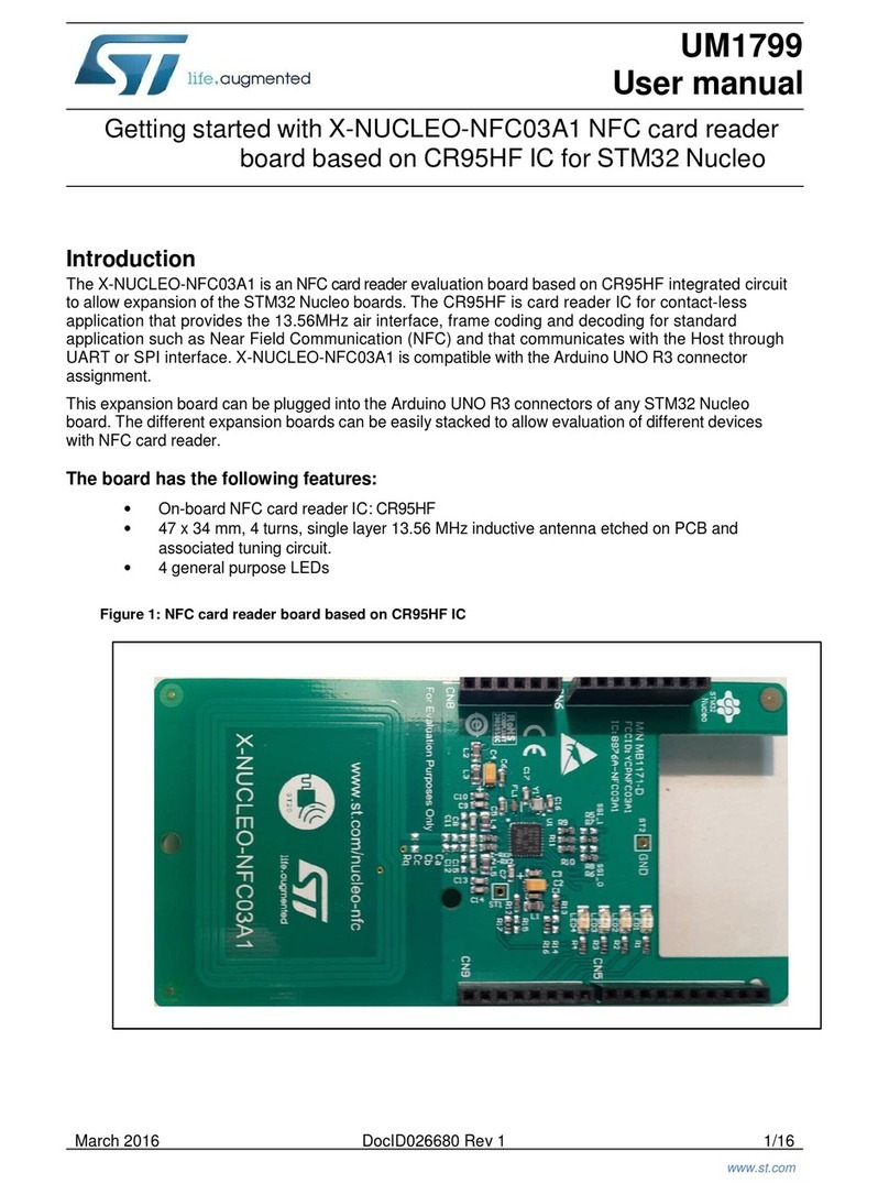
ST STEVAL-IHM011V1 User manual

July 2007 Rev 2 1/27
UM0428
User manual
IGBT Power module evaluation kit - Semitop2 power board
Introduction
The Semitop2 evaluation board STEVAL-IHM011V1 is a complete platform to evaluate
STMicroelectronics power module devices (Semitop 2). Based on a cost effective, flexible
and open design, it is an evaluation platform compatible with the latest STMicroelectronics
microcontroller based solution. It includes the STG3P2M10N60B IGBT Power Module up to
10 amps, 600 voltage (see Note: 1). The STEVAL-IHM011V1 features a motor control
connector (MC-Connector) and hardware features for developing motor control applications
including hardware protection features such as current and thermal protection.
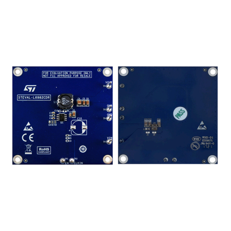
Figure 1. STEVAL-IHM011V1
Features
■34-pin dedicated motor control connector
■5-pin Hall sensor/encoder input
■Tachometer sensor input
■Support for 5 V or 3.3 V microcontroller
■Three configurations for current detection:
– 1 shunt resistor
– 3 shunt resistors or
– 3 external ICS (Insulated Current Sensor)
■Current amplification network
■BEMF detecting network
■Hardware current protection
■Hardware thermal protection (using on board temperature sensor)
■Resistive brake network
Note: 1 The kit has been designed and tested to work with European mains so maximum 380 VDC.
www.st.com

Contents UM0428
2/27
Contents
1 System architecture . . . . . . . . . . . . . . . . . . . . . . . . . . . . . . . . . . . . . . . . . 4
2 Safety and operating instructions . . . . . . . . . . . . . . . . . . . . . . . . . . . . . . 5
2.1 General . . . . . . . . . . . . . . . . . . . . . . . . . . . . . . . . . . . . . . . . . . . . . . . . . . . . 5
2.2 Reference design board intended use . . . . . . . . . . . . . . . . . . . . . . . . . . . . 5
2.3 Reference design board installation . . . . . . . . . . . . . . . . . . . . . . . . . . . . . . 5
2.4 Electronic connection . . . . . . . . . . . . . . . . . . . . . . . . . . . . . . . . . . . . . . . . . 5
2.5 Reference design board operation . . . . . . . . . . . . . . . . . . . . . . . . . . . . . . . 5
3 STG3P2M10N60B power module characteristics . . . . . . . . . . . . . . . . . . 6
3.1 General features . . . . . . . . . . . . . . . . . . . . . . . . . . . . . . . . . . . . . . . . . . . . . 6
4 Power board electrical characteristics . . . . . . . . . . . . . . . . . . . . . . . . . . 7
5 Board architecture . . . . . . . . . . . . . . . . . . . . . . . . . . . . . . . . . . . . . . . . . . . 8
5.1 MC Connector . . . . . . . . . . . . . . . . . . . . . . . . . . . . . . . . . . . . . . . . . . . . . . 9
5.2 Mains connector . . . . . . . . . . . . . . . . . . . . . . . . . . . . . . . . . . . . . . . . . . . . 11
5.3 ICS connector . . . . . . . . . . . . . . . . . . . . . . . . . . . . . . . . . . . . . . . . . . . . . . 12
6 Board schematics . . . . . . . . . . . . . . . . . . . . . . . . . . . . . . . . . . . . . . . . . . 13
6.1 Hardware protection features . . . . . . . . . . . . . . . . . . . . . . . . . . . . . . . . . . 15
6.2 Extra features . . . . . . . . . . . . . . . . . . . . . . . . . . . . . . . . . . . . . . . . . . . . . . 15
7 Motor control demonstration . . . . . . . . . . . . . . . . . . . . . . . . . . . . . . . . . 15
7.1 Environmental considerations . . . . . . . . . . . . . . . . . . . . . . . . . . . . . . . . . 15
7.2 Hardware requirements . . . . . . . . . . . . . . . . . . . . . . . . . . . . . . . . . . . . . . 16
7.3 Power board setup . . . . . . . . . . . . . . . . . . . . . . . . . . . . . . . . . . . . . . . . . . 16
7.3.1 Configuring AC input range and shunt resistors configuration . . . . . . . . 16
7.3.2 Jumpers settings . . . . . . . . . . . . . . . . . . . . . . . . . . . . . . . . . . . . . . . . . . 17
7.4 Microcontroller voltage setting . . . . . . . . . . . . . . . . . . . . . . . . . . . . . . . . . 20
7.5 Sensor voltage setting . . . . . . . . . . . . . . . . . . . . . . . . . . . . . . . . . . . . . . . 21
7.5.1 Board connections . . . . . . . . . . . . . . . . . . . . . . . . . . . . . . . . . . . . . . . . . 21
7.5.2 Changing the current hardware protection level . . . . . . . . . . . . . . . . . . 22

System architecture UM0428
4/27
1 System architecture
The generic motor control system can be schematized as the arrangement of four blocks
(see Figure 2):
●Control block
●Power block
●Motor
●Power supply
Figure 2. Motor control system architecture
The system proposed for the IGBT power module eval kit is composed of one control board
STEVAL-IHM010V1, one power board STEVAL-IHM011V1, one motor and the power
supply.
The control board STEVAL-IHM010V1 is a Microcontroller (ST7MC) based board that
provides the driving signals related to the motor selected and the driving strategies.
Driving signals are constituted of 6 PWM signals in the range of 0-5 V (see Note 2) paired in
High side/low side pairs of one signal for each leg. In the system proposed three legs are
present (three-phase inverter).
The Power Board STEVAL-IHM011V1 is based on a power module (STG3P2M10N60B)
that converts the control signal in the power signals to drive the motor. The connection
between the control board and the power board is performed through a dedicated 32-pin
connector called “motor control connector” (see Section 5.1: MC Connector).
The IGBT power module eval kit is able to drive the following kinds of motors:
●AC induction motor, sensored
●Brushless permanent magnet motor (trapezoidal driven), sensored or sensorless
●Brushless permanent magnet motor (sinusoidal driven), sensored
The power board is supplied by a high voltage AC power supply 220 V (or 110 V) with the
capability to generate current up to 10 amps.
2 The power board can accept control signals in the range of 0-3.3 V if the jumpers are
properly configured.
Control
Block
Power
Block
Power
Supply Moto
r

UM0428 Safety and operating instructions
5/27
2 Safety and operating instructions
2.1 General
During assembly and operation, the IGBT power module eval kit poses several inherent
hazards, including bare wires, moving or rotating parts, and hot surfaces. There is danger of
serious personal injury and damage to property, if it is improperly used or installed
incorrectly.
All operations involving transportation, installation and use, as well as maintenance should
be carried out by skilled technical personnel (national accident prevention rules must be
observed). For the purposes of these basic safety instructions, "skilled technical personnel"
are suitably qualified people who are familiar with the installation, use, and maintenance of
power electronic systems.
2.2 Reference design board intended use
The IGBT power module eval kit boards are components designed for demonstration
purposes only, and shall not be used for electrical installation or machinery. The technical
data as well as information concerning the power supply conditions shall be taken from the
documentation and strictly observed.
2.3 Reference design board installation
The installation and cooling of the reference design boards shall be in accordance with the
specifications and the targeted application.
●The motor drive converters shall be protected against excessive strain. In particular, no
components are to be bent, or isolating distances altered during the course of
transportation or handling.
●No contact shall be made with other electronic components and contacts.
●The boards contain electrostatically sensitive components that are prone to damage
through improper use. Electrical components must not be mechanically damaged or
destroyed (to avoid potential health risks).
2.4 Electronic connection
Applicable national accident prevention rules must be followed when working on the main
power supply with a motor drive. The electrical installation shall be completed in accordance
with the appropriate requirements (e.g., cross-sectional areas of conductors, fusing, PE
connections).
2.5 Reference design board operation
A system architecture which supplies power to the IGBT power module eval kit boards shall
be equipped with additional control and protective devices in accordance with the applicable
safety requirements (e.g., compliance with technical equipment and accident prevention
rules).
STG3P2M10N60B power module characteristics UM0428
6/27
Warning: Do not touch the design boards after disconnection from the
voltage supply, as several parts and power terminals which
contain possibly energized capacitors need to be allowed to
discharge.
3 STG3P2M10N60B power module characteristics
The STG3P2M10N60B is a 1-phase bridge rectifier plus a 3-phase inverter IGBT all
included inside a SEMITOP®2 module.
Figure 3. Power module
●VCES = 600 V
●IC= 10 A at 80 °
●VCE(sat)(max) < 2.5 V at IC=7 A TS=25 °C
3.1 General features
●N-channel very fast PowerMESH™ IGBT
●Lower on-voltage drop VCE(sat)
●Lower CRES / CIES ratio (no cross-conduction susceptibility)
●Very soft ultra fast recovery antiparallel diode
●High frequency operation up to 70 KHz
●New generation products with tighter parameter distribution
●Compact design
●Semitop®2 is a trademark of Semikron

UM0428 Power board electrical characteristics
7/27
4 Power board electrical characteristics
Stresses above the limit shown in Table 2 may cause permanent damage to the device. This
is a stress rating only and functional operation of the device under these conditions is not
implied. Exposure to maximum rating conditions for extended periods may affect device
reliability. 35 V DC Bias Current measurement can be useful to check the working status of
the board. If the measured value is considerably greater than typical value, it means that
some damage has occurred in the board.
3 Before performing the test, the power board must be set up as described in Section 7.3:
Power board setup.
Table 1. Absolute maximum ratings
Symbol Parameter Value Unit
VCES Collector-emitter voltage (VGS = 0) 600 V
IC(1)
1. Calculated value
Collector current (continuous) at Ts= 25 °C 19 A
IC(1) Collector current (continuous) at Ts= 80 °C 10 A
VGE Gate-emitter voltage ±20 V
ICM (2)
2. Pulse width limited by max. junction temperature
TP<1 ms; Ts=25 °C 38 A
ICM TP<1 ms; Ts=80 °C 20 A
IFDiode RMS forward current at Ts= 25 °C 19 A
PTOT Total dissipation at Ts= 25 °C 56 W
VISO
Insulation withstand voltage AC
(t=1 min/sec; Ts=25 °C) 2500/3000 V
Tstg Storage temperature – 40 to 125 °C
TjOperating junction temperature – 40 to 150 °C
Table 2. Control board electrical characteristics
Power board electrical characteristics
STEVAL-IHM011V1
Unit
Min Max
AC Input Voltage J6 without voltage doubler (220 Vac configuration) 24 260 V
with voltage doubler (110 Vac configuration) 12 135 V
DC Input Voltage – J6 35 370 V
DC Bus current 10 A
15 V Auxiliary supply range J8-J9 14 15 V
35 V to J6 Bias current (typical) 50 50 mA

Board architecture UM0428
8/27
5 Board architecture
The STEVAL-IHM011V1 can be schematized as in Figure 4.
Figure 4. Power board architecture
The power board is developed around the IGBT power module that contains the inverter
bridge constituted of six IGBT power switches and the AC rectifier bridge (see Figure 3).
The board has been designed to operate with a 5 V or 3.3 V microcontroller so the power
supply stage provides 15 V, 5 V, and 3.3 V voltage reference respectively for the driver and
for the control board and a configuration can be selected by the jumpers.
4Table 3 indicates the maximum current sourced by the power supply pins of the MC
connector (28 and 25).
The board can be configured to work with three different configurations for current sensing:
●1 Shunt resistor,
●3 Shunt resistors or
●3 Insulated Current Sensor ICS
The amplification network for current sensing is present and configurable for 1 or 3 signals.
In the one-shunt configuration the amplification is positive and the levels of the amplified
signal are compatible with the ST7MC control board STEVAL-IHM010V1 (range 0 V - 5 V).
Table 3. Maximum values of current sourced by internal voltage regulators
Voltage level Max current Unit
+ 5 V 750 mA
+ 3.3 V 900 mA

UM0428 Board architecture
9/27
In the three-shunt configuration, the amplification is positive and an offset is added to keep
the negative values of the current in the range of ADC also. The levels of the amplified
signals are compatible with 3.3 V microcontrollers.
5 To use the ICS, the operational amplifiers U1 network must be modified according to sensor
characteristics. For example using the LTSR 6-NP having Vo=2.5 V + 0.625*I/6 A, the
following steps are required:
– remove R1, R32, R52
– short circuit R21, R22, R44, R45, R65, R66
– replace R4, R28, R54, with 330 Ω
– replace R15, R35, R55 with 680 Ω
The BEMF conditioning network can be configured to use internal or external comparators.
For the ST7MC control board STEVAL-IHM010V1 internal comparators should be used.
The board is featured with a conditioning network for the following kinds of sensors:
●Hall sensors (three inputs H1, H2, H3)
●Encoder (one sensor with three inputs A+, B+, Z+)
●Tachometer sensor (one sensor)
Figure 5 shows the power board layout and the relative connectors.
Figure 5. Power board layout
5.1 MC Connector
The 34-pin MC connector has been designed as the standard to connect the control board
to the power board. Following the configuration of the MC connector, it is possible to design
a different control board or a power board preserving the compatibility between the two

Board architecture UM0428
10/27
systems. For instance it is possible for any user to redesign the control board keeping the
compatibility with the power board if the standard MC connector configuration is used.
Figure 6. MC Connector pin out
Table 4. Motor control connector
Pin N. Description Pin on ST7MC
1 Emergency stop MCES
2 Ground VSS
3 High side PWM phase A MCO0
4 Ground VSS
5 Low side PWM phase A MCO1
6 Ground VSS
7 High side PWM phase B MCO2
8 Ground VSS
9 Low side PWM phase B MCO3
10 Ground VSS
11 High side PWM phase C MCO4
12 Ground VSS
13 Low side PWM phase C MCO5
14 BUS voltage AIN1
15 Phase A current
GNDFault (Shut_Down L6386)
PWM_1H
PWM_1L
PWM_2L
PWM_2H
PWM_3H
PWM_3L
NTC bypass Relay
5V
GND
GND
GND
GND
GND
GND
Current PhaseA
Current PhaseB
Current PhaseC
GND
GND
GND
Dissipative Brake PWM
Bus voltage
Heatsink temperature
GND
PFC PWM
PFC Sync
1
3
5
7
9
11
13
15
17
19
21
23
25
2
4
6
8
10
12
14
16
18
20
22
24
26
27 28
29 30
31 32
33 34
Encoder A
Encoder B Encoder Index
3V3
GND
GND
Dedicated
A
DC[n]
A
DC[n+1]
A
DC[n+2]
GPI
O
GP PWM
GP capture
GP PWM
Dedicated
A
DC
A
DC
GP Capture

UM0428 Board architecture
11/27
5.2 Mains connector
A mains connector is used to supply the board. Connect the mains between pin 2 and 3 of
J6.
Pin 1 of J6 is used to connect to earth. It is also possible to connect the chassis of the motor
to pin 1 of J5.
Figure 7. Mains connector
16 Ground VSS
17 Phase B current MCCFI
18 Ground VSS
19 Phase C current
20 Ground VSS
21 NTC PYPASS RELAY
22 Ground VSS
23 Dissipative BRAKE PC2
24 Ground VSS
25 5 V VDD
26 HEATSINK temperature AIN0
27 PFC SYNC ICAPx_B
28 3V3
29 PFC PWM OCMP1_B
30 Ground VSS
31 ENCODER A MCIA
32 Ground VSS
33 ENCODER B MCIB
34 ENCODER INDEX MCIC
Table 4. Motor control connector (continued)
Pin N. Description Pin on ST7MC

Board architecture UM0428
12/27
5.3 ICS connector
The ICS Connector is used to connect the Insulated current sensor to the board. See
Table 5 for pin out.
Figure 8. ICS connector
Table 5. ICS connector pin out
Pin Function
1 Ground
2 Ground
3 ICS Input C
4 GND ICS Input C
5 ICS Input B
6 GND ICS Input B
7 ICS Input A
8 GND ICS Input A
9+5V
10 Ground

UM0428 Board schematics
13/27
6 Board schematics
Figure 9. Power board schematic - page 1

Board schematics UM0428
14/27
Figure 10. Power board schematic - page 2

UM0428 Motor control demonstration
15/27
6.1 Hardware protection features
The L6386 drivers are used to drive the three-phase bridge. The drivers are provided with
internal protection features used for hardware current and thermal protection.
Hardware current protection has been set up for a current level of 4 amps. If a current
greater than this value flows inside the motor, the inverter is shut down and an emergency
fault signal is sent to the micro by the MC connector.
To change the value of current protection, read Section 7.5.2: Changing the current
hardware protection level.
A sensor is also present on the board that monitors the temperature of the power bridge. If
the temperature threshold of 60 °C is reached, the inverter is shut down and an emergency
fault signal is sent to the micro by the MC connector.
The bus voltage is also monitored using a voltage divider. No hardware protection for over
voltage is implemented, but the value is sent to the control board via the MC connector.
6.2 Extra features
A resistive brake network is present on the board. The expected control signal is pin 23 of
the MC connector drive.
To use this feature, a control board is required with a resistive brake control strategy
implemented.
6 The software to address this feature is not currently implemented in the STEVAL-
IHM010V1.
An external power resistor sized for the specific application must be mounted between pin 1
and pin 2 of J7.
7 Motor control demonstration
7.1 Environmental considerations
Warning: The IGBT power module eval kit must only be used in a power
laboratory. The high voltage used in any HV drive system
presents a serious shock hazard.
The kit is not electrically isolated from the AC input. This topology is very common in AC
drives. The microprocessor is grounded by the integrated ground of the DC bus. The
microprocessor and associated circuitry are hot and MUST be isolated from user controls
and serial interfaces.

Motor control demonstration UM0428
16/27
Warning: Any measurement equipment must be isolated from the main
power supply before powering up the motor drive. To use an
oscilloscope with the kit, it is safer to isolate the AC supply
AND the oscilloscope. This prevents a shock occurring as a
result of touching any SINGLE point in the circuit, but does
NOT prevent shocks when touching TWO or MORE points in
the circuit.
An isolated AC power supply can be constructed using an isolation transformer and a
variable transformer. A schematic of this AC power supply is in the Application note,
"AN438, TRIAC + Microcontroller: Safety Precautions for Development Tools." (Although
this Application Note was written for TRIAC, the isolation constraints still apply for fast
switching semiconductor devices such as IGBTs.)
7 Isolating the application rather than the oscilloscope is highly recommended in any case.
7.2 Hardware requirements
To set up the IGBT power module eval kit system, the following items are required:
●The control board: STEVAL-IHM010V1
●The power board: STEVAL-IHM011V1
●34-pin flat cable
●High Voltage isolated AC power supply up to 220 V 10 A
●Isolated DC power supply up to 30 V 3 A
●Softec inDART-STX (not included in the package)
●Softec ICC Isolation board (not included in the package)
●Two 10-pin flat cable (not included in the package)
●AC Induction motor Selni (not included in the package)
●Brushless PM motor Ametek (not included in the package)
●Insulated oscilloscope (as needed)
●Insulated multimeter (as needed)
A complete laboratory setup consists of an isolated AC power supply, one AC Induction
motor or one PM Brushless motor, and one isolated power supplies for +15 V (as needed).
See the STEVAL-IHM010V1 user manual for the configuration of the control board before
proceeding.
7.3 Power board setup
7.3.1 Configuring AC input range and shunt resistors configuration
The STEVAL-IHM011V1 power board can be configured for two ranges of AC input voltage:
European standard mains voltage (220 Vac) or American standard mains voltage (110 Vac).

UM0428 Motor control demonstration
17/27
The first configuration is a simple rectifier, but the second configuration is a voltage doubler.
Using the first configuration with an AC input of 220 V, the bus voltage obtained is 310 DC
volt. Using the second configuration with an AC input of 110 V, the bus voltage obtained is
the same 310 DC V. To configure the board for the voltage doubler (up to 110 Vac input),
solder a wire closing the two pins of W15.
To configure the board for a simple rectifier (up to 220 Vac input), keep W15 open.
The power board can be configured to use a single-shunt resistor or a three-shunt resistor.
8 To use ICS the board must be configured for three-shunt resistors and the operational
amplifier networks as described on page 9 must be modified.
To configure the board for a single shunt, wires must be soldered between point 1 and point
2 of W17 and W20 while keeping point 3 open.
To configure the board for three shunts, wires must be soldered between point 2 and point 3
of W17 and W20 while keeping point 1 open.
Figure 11. a) single-shunt configuration b) three-shunt configuration
7.3.2 Jumpers settings
Tabl e 6 describes individually each jumper functionality.
a)
b)

Motor control demonstration UM0428
18/27
Table 6. Jumpers settings
Name Selection Description
W1
Between 1-2
If sensorless control is set (see W2), it connects motor phase A to MC connector through
R2-R3-R5-R6 feedback resistors. In this case the microcontroller internal comparator is
used to detect the BEMF.
Between 2-3 The external comparator U2A is used to detect the BEMF. If sensorless control is set (see
W2), it connects the output of U2A to MC connector.
Not present Use this setting for sensored control (Tacho, Encoder, Hall)
W2
Between 1-2 It is used for sensorless control. Connects motor phase feedback signal to MC connector.
Between 2-3 It is used for sensored control. Connects the Hall sensor signal or Encoder signal to MC
connector.
W3 Present 3-Shunt setting. It is used to set the correct values for the current amplifier U1B.
Not present 1-Shunt setting. It is used to set the correct values for the current amplifier U1B.
W4
Between 1-2 It is used for sensorless control. Connects motor phase feedback signal to MC connector.
Between 2-3 It is used for sensored control. Connects the Hall sensor signal or Encoder signal to MC
connector.
W5 Not present 1-Shunt setting. It is used to set the correct values for the current amplifier U1B.
Between 2-3 3-Shunt setting. It is used to set the correct values for the current amplifier U1B.
W6 Between 1-2 Sets the voltage supplied to Hall / Encoder Sensors to Vdd_Micro values (see W13).
Between 2-3 Sets the voltage supplied to Hall / Encoder Sensors to +5 V.
W7
Between 1-2
If sensorless control is set (see W4), it connects motor phase B to MC connector through
R29-R30-R32-R33 feedback resistors. In this case the microcontroller internal comparator
is used to detect the BEMF.
Between 2-3 The external comparator U2B is used to detect the BEMF. If sensorless control is set (see
W4), it connects the output of U2B to MC connector.
Not present Use this setting for sensored control (Tacho, Encoder, Hall)
W8 Present 3-Shunt setting. It is used to set the correct values for the current amplifier U1B.
Not present 1-Shunt setting. It is used to set the correct values for the current amplifier U1B.
W9
Between 1-2 It is used for sensorless control. Connects motor phase feedback signal to MC connector.
Between 2-3 It is used for sensored control. Connects the Hall sensor signal or Encoder signal to MC
connector.
W10
Between 1-2 It selects the voltage reference for the comparator U2A, U2B and U2C to detect zero
crossing. The reference VBus/2 is reconstructed using voltage divider from VBus.
Between 3-4
It selects the voltage reference for the comparator U2A, U2B and U2C to detect zero
crossing. The reference VBus/2 is reconstructed using Phase A, Phase B and Phase C
values.
Between 5-6 It selects the voltage reference for the comparator U2A, U2B and U2C to detect zero
crossing. The reference is set using PWM Vref coming from MC connector.

UM0428 Motor control demonstration
19/27
If the STEVAL-IHM010V1 is used, Ta bl e 7 can be used to configure the jumper related to
the driving strategy.
W11
Between 1-2
If sensorless control is set (see W9), it connects motor phase C to MC connector through
R59-R60-R61-R62 feedback resistors. In this case the microcontroller internal comparator
is used to detect the BEMF.
Between 2-3 The external comparator U2C is used to detect the BEMF. If sensorless control is set (see
W9), it connects the output of U2C to MC connector.
Not present Use this setting for sensored control (Tacho, Encoder, Hall)
W12 Present It is used to connect Tachometer sensor signal, already conditioned, to "Measure Phase
C" pin of MC connector. W9 jumper must be not present.
Not Present Tachometer input is not connected.
W13
Between 1-2 It sets Vdd_Micro value to +3.3 V.
Between 2-3 It sets Vdd_Micro value to +5 V.
Not present Pin 28 of MC connector is not supplied
W14 Present It connects the +5 V to pin 25 of MC connector.
Not present Pin 25 of MC connector is not supplied.
W16
Between 1-2 Use this setting if the Mains is above 24 Vac. VIPer is used to obtain 15 V.
Between 2-3 Use this setting if the Mains is below 24 Vac. L7815 regulator is used to obtain 15 V.
Open Leave open if +15 V DC external power supply is used.
W18 Present(1) Connect the Diag signal of the driver to the Fault pin 1 of MC connector through the U12A
used to adapt voltage level.
Not Present Fault pin 1 of MC connector is not connected.
W19 Present(1)
Connect the comparator U5A "Thermal Protection" to the shutdown pin of the driver. When
over temperature occurs based on U5A comparison (see Temp_Vref in the schematic) the
drivers are stopped.
W21
Not Present Remove it to disconnect "Thermal Protection" measured by U5A with the shutdown pin of
the driver.
Between 1-2 Use this setting for shunt resistor feedback
Between 2-3 Use this setting for ICS feedback
W22 Between 1-2 Use this setting for shunt resistor feedback
Between 2-3 Use this setting for ICS feedback
W23 Between 1-2 Use this setting for shunt resistor feedback
Between 2-3 Use this setting for ICS feedback
W24 Open Overvoltage threshold settings. Use this setting when the micro is supplied with 5 V
Closed Use this setting when the micro is supplied with 3.3 V
1. Default setting
Table 6. Jumpers settings (continued)
Name Selection Description

Motor control demonstration UM0428
20/27
Table 8 indicates the jumpers related to the current amplification settings. Set the jumper as
in Ta b l e 8 .
7.4 Microcontroller voltage setting
W13 sets the voltage supplied to the microcontroller.
If W13 is set between 1-2, +3.3 voltage is supplied to the microcontroller via the MC
connector.
If W13 is set between 2-3, +5 voltage is supplied to the microcontroller via the MC
connector.
Table 7. Configuration for each firmware
Driving strategy Jumper name Selection
AC Ind. Motor
W2, W4, W9 open
W12 closed
W1, W7, W11 open
BLDC Sensorless
W2, W4, W9 between (1-2)
W12 open
W1, W7, W11 between (1-2)
BLDC Sensored
W2, W4, W9 between (2-3)
W12 open
W1, W7, W11 open
BLAC Sensored
W2, W4, W9 between (2-3)
W12 open
W1, W7, W11 open
Table 8. Jumper settings
Single-shunt configuration
W3 not present
W5 not present
W8 not present
Three-shunt configuration and ICS
W3 present
W5 present between 2-3
W8 present
Table of contents
Other ST Motherboard manuals

ST
ST STM32 Nucleo User manual

ST
ST STM32L5 Nucleo-144 board User manual

ST
ST EVB-LIV3F User manual

ST
ST STEVAL-BLUEMIC-1 User manual

ST
ST STEVAL-WBC86TX User manual

ST
ST STEVAL-ISB68RX User manual

ST
ST STMPE821 User manual

ST
ST STEVAL-MKI132V1 User manual

ST
ST STM3241G-EVAL User manual

ST
ST STM32H753I-EVAL User manual