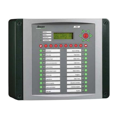
Fancom 750 User manual

LUMINA 750
LUMINA 750 TOUCH
750
USER MANUAL
VERSION N1

N.B.: The original, authentic version of this manual is the English version produced by Fancom B.V. or one of its
daughter companies (referred to further as Fancom). Any modifications introduced to this manual by third parties
have neither been checked nor approved by Fancom. Modifications are taken by Fancom to include translations
into languages other than English and the insertion and/or deletion of text and/or illustrations to/from the original
contents. Fancom cannot be held liable for any damages, injury, guarantee claims and other claims relating to
this type of modification, in as far as these modifications result in a content that differs from the original English
version of this manual produced by Fancom. For the latest information about product installation and operation,
please contact the customer service dept. and/or the technical service dept. of the Fancom concerned. In spite
of the care taken when compiling this manual, if you should discover any errors, please inform Fancom B.V. in
writing. Fancom B.V., PO Box 7131, 5980 AC Panningen (the Netherlands).
Copyright © 2020 Fancom B.V.
Panningen (the Netherlands)
All rights reserved. Nothing from this manual may be copied, distributed or translated into other languages, partly
or wholly, without express prior written permission from Fancom. Fancom reserves the right to modify this manual
without notice. Fancom can give no guarantee, neither implicit nor explicit, for this manual. All risks are for the
user.
This manual has been compiled with the utmost care. If, however, you should discover an error, please inform
Fancom B.V.
Art.Nr. 5911223
GB2020-08-04

Lumina 750
Table of contents
1. General introduction ............................................................................................................................... 1
1.1 Documentation with the control computer ................................................................................... 1
1.2 How to use this manual ............................................................................................................... 1
1.3 Fancom Sales & Service Center ................................................................................................. 1
1.4 F-Central FarmManager™ ........................................................................................................... 2
2. Basic working principles ........................................................................................................................ 3
2.1 Principle diagram tunnel .............................................................................................................. 3
2.2 14 tunnel phases ......................................................................................................................... 3
2.3 Phase settings ............................................................................................................................. 5
2.4 Controls ........................................................................................................................................ 5
2.5 Working per tunnel phase ........................................................................................................... 7
2.6 Working per sub-phase ............................................................................................................. 12
3. Using the Lumina 750 ........................................................................................................................... 14
3.1 Overview screen ........................................................................................................................ 14
3.2 Trends ........................................................................................................................................ 25
3.3 Conditions .................................................................................................................................. 26
3.4 Controls ...................................................................................................................................... 27
4. Alarm ....................................................................................................................................................... 29
4.1 Alarm overview .......................................................................................................................... 29
4.2 Alarm settings ............................................................................................................................ 32
4.3 Alarm history .............................................................................................................................. 33
5. Maintenance ........................................................................................................................................... 34
6. Classic screens ..................................................................................................................................... 35
6.1 Classic screen: Overview screen .............................................................................................. 35
6.2 Function key 1: Overview .......................................................................................................... 35
6.3 Function key 2: Compost/tunnel temp. ...................................................................................... 37
6.4 Function key 3: Air inlet temperature ........................................................................................ 38
6.5 Function key 4: O2/CO2/NH3 .................................................................................................... 40
6.6 Function key 5: RH .................................................................................................................... 40
6.7 Function key 6: Fresh air .......................................................................................................... 41
6.8 Function key 7: Fan ................................................................................................................... 42
6.9 Function key 8: Heating/cooling/steam ...................................................................................... 43
6.10 Function key 9: Phase times ..................................................................................................... 45
6.11 Function key 10: Actual settings ............................................................................................... 46
6.12 Function key 11: Time/time clock/registr. ................................................................................... 48
6.13 Function key 12: Alarm settings ................................................................................................ 50
6.14 Function key 13: Levelling ......................................................................................................... 51
6.15 Function key 14: Warm up pasteurization ................................................................................. 52
6.16 Function key 15: Pasteurization ................................................................................................ 52
6.17 Function key 16: Cool down conditioning .................................................................................. 52
6.18 Function key 17: Conditioning ................................................................................................... 52
6.19 Function key 18: Cool down spawning ..................................................................................... 53
6.20 Function key 19: Spawn run ..................................................................................................... 53
6.21 Function key 20: Outside conditions ......................................................................................... 54
6.22 Function key 21: Special actions ............................................................................................... 54
6.23 Messages when changing settings ............................................................................................ 57
6.24 Password ................................................................................................................................... 57
Lumina 750 General introduction
1. General introduction
This manual has been created with the utmost care. If, however, you should discover an error, please inform
Fancom B.V..
1.1 Documentation with the control computer
The documentation consists of the following manuals:
●User's manual
The user's manual is intended for the end user. This manual supplies information about working with the
control computer after installation.
●Installer's manual
The installer's manual is intended for installers. This manual supplies information about connecting and
configuring the control computer.
●Operation and safety instructions
These subjects are covered in a separate manual. This manual also applies to other control computers in
the Fancom F2000-line. Always read the safety instructions and warnings carefully before using the control
computer.
Always keep this manual close to the Lumina 750.
1.2 How to use this manual
The following symbols are used in this manual:
Tips and suggestions.
Note providing recommendations and additional information.
Warning indicating damage to the product if you do not follow procedures carefully.
Warning indicating danger to humans or animals.
Electric shock hazard. Danger to humans and animals.
Example of a practical application of the described functionality.
Calculation example.
Describes the key combinations for arriving at a particular screen.
Decimals
The control computer and this manual use a decimal point in values. For example: a weight is shown as 1.5 kg
(not as 1,5 kg).
1.3 Fancom Sales & Ser ice Center
For any questions and support, please contact the local Fancom Sales & Service Center.
1

Lumina 750 General introduction
1.4 F-Central FarmManager™
Virtually all Fancom equipment can be controlled and managed from a central location. This requires the F-
Central FarmManager software package and a communication module. The screens in the control computers are
also used in F-Central FarmManager. This means you can start working immediately.
2

Lumina 750 Basic working principles
2. Basic working principles
2.1 Principle diagram tunnel
M
T
T
p
V
M
TdTw
T T T
T T T
T
RH
Td
Tw
TUNNEL
Fresh air
Fresh air
Tunnel air
temperatures
Cooling
Recirculation
Circulation
Air intake temp.
dry/wet bulb
Fan
H/L
O2
tunnel
Circulation
Steam
Compost
temp. 1
Compost
temp. 2
Compost
temp. 3
Compost
temp. 4
Compost
temp. 5
Compost
temp. 6
alternative:
Measuring fan
recirculation
eventual
O2 measurement
alternative:
Measuring fan
recirculation
O2 outside
alternative:
Air measurement
by air pressure
OUTSIDE
alternative:
Electr. RH + outside temp.
RH measurement box
outside
Figure 1: Principle diagram tunnel
2.2 14 tunnel phases
Composting consists of 14 phases. Each phase requires a specific climate. The graph below shows an example
of a composting cycle.
3

Lumina 750 Basic working principles
Para-
meter
Empty Level-
ling
Warm
up
pas-
teuriz-
ation
1&2
Pas-
teuriz-
ation
Cool
down
condi-
tion-
ing
Con-
dition-
ing
1&2
Cool
down
spawn-
ing
Spawn
run
1,2&3
Deliv-
ery
Warm
up
cook
ou
Cook
out
Cool
down
cook
out
Com-
post
temp
(ºC)
n.a. 45 45-57 56-58 58-48 48 48-28 25-27 25-27 graph +/- 70 graph
Inlet
temp.
(ºC)
Frost
free
43 43-56 +/- 55 55-45 42-46 46-23 20-24 20-24 max.
75
+/- 70 graph
O2
(%)
12-18 12-18 12-18 12-18 12-18 12-18 n.a. n.a. n.a. n.a n.a n.a
Fr. air
m3/ton
0 15-200 15-30 15-100 15-100 15-200 15-200 15-200 15-200 0 0 inst.
Fan
m3/ton
0 max.
200
max.
200
max.
200
max.
200
+/-
50-200
50-200 50-200 50-200 stand
1
stand
1
stand
1
Rime n.a. 4-12h +/- 10h 6-12h 6-12h 4-5
days
12-24h 12-16
days
n.a. set-
table
set-
table
set-
table
0 1
2/3
4 5 6/7 8 9 10/11
12 13 14
70 (158)
60 (140)
50 (122)
40 (104)
30 (86)
20 (68)
10 (50)
Temperature °C (°F)
Tunnel phase
Comp.
temp.
Air inlet
temp.
Air inlet
temp.
Figure 2: Tunnel phases with typical parameters
Sub-phases
Parameter Cleaning Disinfection Filling O2 calibration
Fresh air Settable 0 Settable Settable
Fan Settable Settable Settable Settable
Duration Settable Settable Settable Settable
Exhaustvalve 0 0 Settable 0
4

Lumina 750 Basic working principles
2.3 Phase settings
Fancom divides the settings into four groups:
1. Current phase settings
2. Phase pre-settings
3. Extra phase settings
4. Sub-phase settings
The Current phase settings are the settings used by the Lumina 750 to control at this moment in the process.
A number of pre-settings have been entered for each growing phase, the Phase pre-settings. These phase pre-
settings have their own address in the computer memory. As soon as a certain growing phase activates, the
computer starts copying the phase settings concerned to the current phase settings. While a certain phase is
active, the current settings can be changed. The phase pre-settings will remain unchanged in the computer
memory.
A number of additional settings can be entered for some phases, the Extra phase settings. These settings are
only relevant for a particular tunnel phase.
A number of settings can also be entered for the sub-phases; the Sub-phase settings such as cleaning,
disinfection and filling.
2.4 Controls
The Lumina 750 has the following climate controls:
●Air inlet temperature control
●Relative humidity control
●Circulation control
●Compost temperature control
●.O2-control
●Fresh air control
●Thermal control
●Pressure control
2.4.1 Air temperature control
The Lumina 750 controls the air temperature by measuring the following:
●Inlet air temperature
A sensor measures the dry and wet inlet temperature into the the tunnel. The sensors are located behind the
fan.
The desired air temperature is achieved by:
●Fresh air for cooling
Cooler air from outside is mixed with the recirculated air in the tunnel until the air temperature reaches the
required value.
●Heating
●Cooling
●Steam
2.4.2 Humidity control
Relative humidity control (RH control)
This control ensures that the relative humidity in the tunnel is constantly at the correct level.
A too low relative humidity can be increased by:
●humidifying the supply air using steam or cold water.
5

Lumina 750 Basic working principles
2.4.3 Circulation control
The Lumina 750 controls the circulation by speed of the fan. The circulation control has the following functions:
●Correct air distribution in the tunnel,
●Bringing or keeping the temperature differences in the compost within acceptable limits,
●Ensuring a more intensive heat exchange between the air and the compost if there are too high compost
temperatures.
Control options
How the circulation is controlled is determined by one of four fan control options, namely: %, m3/h, m3/h/t and %/
t. One of these is selected during installation (see the Installation manual).
The Lumina 750 determines the circulation based on this configuration:
• %: Circulation values are set and displayed in %.
• m3/h: Circulation values are set and displayed in cubic metre per hour.
• m3/h/t: Circulation values are set and displayed in cubic metre per hour. The total amount of tonnage in the
tunnel is used to calculate the minimum and maximum circulation.
• %/t: Circulation values are set and displayed in %, but the percentage depends on the tonnage in tunnel. The
percentage is pre-set in the circulation table.
Circulation table
Only the option %/t uses the circulation table (see picture below).
The circulation table gives optimal control of circulation. Each phase has a circulation table (pre-phase setting).
The table links the tonnage (T) to a certain amount of circulation (minimum, maximum and increase/day in %).
After setting up this table, the Lumina 750 automatically selects the right amount of circulation (%) for the tonnage
that is in the tunnel.
The pre-set amounts of compost (T) in the circulation table are the same for all pasteurisation phases and all
mycelium phases.
2.4.4 Compost temperature control
The Lumina 750 uses the air temperature to control the compost temperature. If the average compost
temperature is higher or lower compared to the Compost temperature control value, the difference can be
corrected by adjusting the air temperature.
A too high compost temperature can be decreased by increasing the fan speed. The fan speed will create a more
intensive heat exchange between the compost and the air.
The compost temperature control can also be used to eliminate differences between compost temperatures. The
fan speed will be used for levelling the compost temperatures.
2.4.5 O2 control
The Lumina 750 controls the O2 concentration on the basis of the O2 control value. If the O2 content drops below
the control value, fresh air will be introduced in the tunnel, even if the air inlet temperature is too low. If the O2
concentration rises above the control value, the amount of fresh air will be decreased.
6

Lumina 750 Basic working principles
2.4.6 Fresh air control
The Lumina 750 controls the amount of fresh air to regulate the air temperature and O2 content. Two settings
are used for fresh air control: the minimum and maximum fresh air settings. The fresh air control value is always
between these two limits. The Lumina 750 calculates the control value depending on the air inlet temperature or
O2. If both influences are present, the greatest influence applies.
2.4.7 Thermal control
Thermal control is an universal temperature control that is used as:
●An independent temperature control for a pre-heater or pre-cooler (with its own temperature setting),
●A second heating control (coupled to the first heating control),
●A second cooling control (coupled to the first cooling control).
The Lumina 750 has 3 seperate thermal controls. Switch between these 3 via the index. For example see
Function key 8: Heating/cooling/steam (page 43).
2.4.8 Pressure control
The Lumina 750 can measure the pressure to control the exhaust air damper.
2.4.9 Measurement
The Lumina 750 can measure the following:
●O2-concentration
●CO2
●Ammonia
●Air flow
2.5 Working per tunnel phase
Tunnel phases and sub-phases will be explained below:
2.5.1 PHASE 1: Le elling
Aim To bring the compost temperature to a required value within a certain period of time, or to level
the temperature differences within the compost.
Uses ●.fresh air to cool and to maintain the O2-concentration
●fan to level compost temperatures
●heating and steam (in some cases)
Method ●levels during a pre-set time. Switches to other phases irrespective of the compost condition.
●levels until the compost has reached the required condition. The Lumina 750 determines
when the switch is made to the next phase. If the compost does not reach the correct
conditions within the maximum levelling time, the Lumina 750 will automatically switch to the
next phase.
7

Lumina 750 Basic working principles
Compost temperature control value: 45.0°C (113°F)
Levelling: minimum phase time: 6 hours
Levelling: maximum phase time: 12 hours
Temperature margin compost: 1.0°C (33.8°F)
Difference compost: 2.0°C (35.6°F)
2
4
6
8 10 12 14
50 (122)
48 (118)
46 (114)
44 (111)
42 (107)
40 (104)
Temperature °C (°F)
Time (hours)
Max. measured compost temp.
Min. measured compost temp.
Average compost
temperature
Compost temperature
control value
2°C (35.6°F)
Max. phase time
Min. phase time
Figure 3: Switch over to next phase when levelling
●Use a large air inlet temperature control range
●Use an increased fan speed
2.5.2 PHASE 2 & 3: Warm up pasteurization
The warming up can be realised in two phases with different parameters.
Aim To gradually increase the compost temperature to the pasteurization temperature.
Uses ●steam and heating as a heat source to warm up the air
●the fan to minimize temperature differences
●.fresh air to cool if the temperatures rises too fast and to maintain a minimum O2-
concentration.
Method Increases the tunnel temperature to pasteurization temperature according to a preset speed
using steam. Usually the compost temperature is 1.0°C (1.8°F) or 2.0°C (3.6°F) higher than the
air inlet temperature.
2.5.3 PHASE 4: Pasteurization
Aim To maintain the compost and air inlet temperature at a high value during a certain period of
time in order to kill unwanted organisms. This phase is ended as soon as the entered time
has elapsed or when the average compost temperature rises above the maximum compost
temperature, after the minimum phase time has been elapsed.
Uses ●the fan to minimize temperature differences
●.fresh air to cool or to maintain a minimum O2 concentration
Method -
8

Lumina 750 Basic working principles
Required air inlet temperature 57.0°C (134.6°F)
End value compost temperature 58.0°C (136.4°F)
Maximum compost temperature 61.0°C (141.8°F)
Pasteurization: minimum phase time 4 hours
Pasteurization: maximum phase time 6 hours
61 (141)
59 (138)
57 (134)
55 (131)
53 (127)
51 (123)
Temperature °C (°F)
Warm up
pasteurization
Min. phase time
(4 hours)
Max. phase time
(6 hours)
Actual pasteurization
time
Time (hours)
Air inlet temperature
End value compost
Max. compost temp.
Measured compost temp.
Figure 4: Pasteurization
2.5.4 PHASE 5: Cool down conditioning
Aim To cool down the compost temperature to the end value compost temperature.
Uses ●.fresh air to cool and to maintain a minimum O2 concentration
●the fan to minimize temperature differences
●cooling (usually not used)
Method Increases the fan speed to cool down the compost temperature. The air inlet temperature must
not be set too low, otherwise the compost temperature could collapse.
2.5.5 PHASE 6 & 7: Conditioning
The conditioning can be realised in two phases with different parameters.
Aim To maintain a constant compost temperature during a certain time (4 or 5 days) until there is no
longer any ammonia in the compost. The grower decides when to stop this phase, based on his
ammonia readings.
Uses ●fresh air to cool
●the fan to minimize temperature differences
●cooling (usually not used)
Method -
9

Lumina 750 Basic working principles
2.5.6 PHASE 8: Cool down spawning
Aim To quickly decrease the compost temperature to the required value so that spawn can be
applied. This phase can be ended by selecting the next phase manually.
Uses ●fresh air to cool
●the fan to minimize temperature differences
Method Cools the air inlet and compost temperature using the air inlet, sometimes using cooling.
Cooling down should be carried out as quickly as possible. The time needed depends on the air
conditioning unit capacity and the outside temperature conditions.
2.5.7 PHASE 9 - 12: Spawn run 1 - 3 / Deli ery
Aim To maintain the compost temperature at a required temperature for optimal spawn (mycelium)
development. The grower decides when to stop this phase. As the compost temperature is the
most important factor in this phase, this should also influence the ideal air inlet temperature.
The grower decides when the tunnel should be ready for delivery, by setting his parameters for
the delivery phase. If needed he will decide for a compost temperature decrease to maintain
temperature during transportation.
Uses ●fresh air to cool
●fan to minimize temperature differences
●cooling
●humidifying
Method Maintains the air inlet temperature at the correct value using fresh air or cooling. The compost
temperature determines the correct air inlet temperature value.
28 (82)
26 (78)
24 (75)
22 (71)
20 (68)
18 (64)
Temperature °C (°F)
Time
Min. air temperature
Required air temp.
Max. air temperature
Required compost temp.
Measured compost temperature
Control range air
temperature
Figure 5: Spawn run 1
●use a large control range for the air inlet temperature
●use the fan control optimally
10

Lumina 750 Basic working principles
2.5.8 PHASE 13: Warm up cook out
Aim To reach a certain air inlet and compost temperature (70.0°C (158.0°F)).
Uses ●heating
●steam
Method Increases the air inlet temperature to the required air inlet temperature using steam and/or
heating. The air inlet is closed. After a certain time the compost will also reach the required cook
out temperature. The Lumina 750 will then automatically switch to the next phase.
2.5.9 PHASE 14: Cook out
Aim To maintain the air inlet and compost temperature at required temperature for a certain time
(usually 12 hours) in order to kill all bacteria and mycelium. The grower decides to switch to the
next phase after the cook out time has elapsed.
Uses ●the fan for a correct temperature distribution
●heating
●steam
Method Maintains the cook out temperature in the tunnel during the set time.
2.5.10 PHASE 15: Cool down cook out
Aim To decrease the tunnel temperature.
Uses ●natural cooling
●fresh air
Method After the cook out phase the air inlet can be closed during a set phase time. The tunnel can cool
down without using outside air. This is better for the building. After the minimum phase time has
elapsed (14a) the Lumina 750 will open the air inlet to cool the tunnel. After the maximum phase
time has elapsed (14b) the computer will switch to the empty phase; the fan will be deactivated
and the air inlet closed.
11

Lumina 750 Basic working principles
70 (158)
60 (140)
50 (122)
40 (104)
30 (86)
20 (68)
10 (50)
6
12
18
24
30 36 42 48 54
Temperature °C (°F)
Time (hours)
Warm up cook out
Natural
cool down time
Max. phase time cool down
cook out
Empty
Cook out
Phase
13
Phase
14
Phase
15a
Phase
15b
Phase
0
Measured compost temperature
Measured air temperature
Figure 6: Compost and air temperature during cook out
phase 13 The fan is activated and the air inlet is closed (warm up).
phase 14 The fan is activated and the air inlet is closed. This period lasts e.g. 12 hours
phase 15a The fan is activated or deactivated and the air inlet is closed (natural cooling). This
period lasts e.g. 6 hours (extra time setting).
phase 15b The fan is activated and the computer controls the air inlet based on temperature (if
set). This period equals the time remaining for cool down. At the start of the period
cooling had already been active for 6 hours; there are 30 hours remaining for this
period.
phase 0 The fan is deactivated and the tunnel is closed.
2.6 Working per sub-phase
2.6.1 SUB-PHASE: Cleaning
Aim Cleaning the tunnel after using chemical disinfectants.
Uses ●fan
●fresh air
Method The cleaning sub-phase can be used only during the empty phase. This sub-phase can be
started/stopped by pressing the cleaning button. The cleaning button is an external button
placed outside of the controller. The subphase can also be started by entering the required
subphase at
1
Overview - Sub-phase.
12

Lumina 750 Basic working principles
2.6.2 SUB-PHASE: Disinfection
Aim Killing flies and/or larvas during spawn run.
Uses ●fan
●a fresh air inlet which automatically closes to keep the pesticide in the tunnel
Important The disinfection sub-phase can be used only during the spawn run 1 and 2. This sub-phase can
be started/stopped by pressing the disinfecting button. The disinfection button is an external
button placed outside of the controller. The subphase can also be started by entering the
required sub-phase at
1
Overview - Sub-phase.
2.6.3 SUB-PHASE: Filling
Aim Filling the tunnel for a new round.
Uses ●fan
●fresh air
Important The filling sub-phase can be used only during the empty phase. This sub-phase can be started/
stopped by pressing the external placed button. The disinfection button is an external button
placed outside of the controller. The subphase can also be started by entering the required sub-
phase at
1
Overview - Sub-phase.
2.6.4 SUB-PHASE: Empty
Aim A transitional phase between the emptying and filling of a tunnel. This phase also prevents frost
damage to buildings and equipment.
Uses Frost protection.
Method -
13

Lumina 750 Using the Lumina 750
3. Using the Lumina 750
3.1 O er iew screen
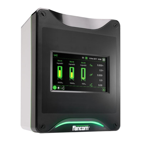
The Lumina 750 displays the Overview screen by default. This screen provides a complete overview of the
current composting cycle status in a tunnel and the equipment managed by the control computer. The figure
below gives an example of the Overview screen. This image may differ from your screen due to different settings
and measurement values.
3.1.1 Title bar
Title bar
Room Readout/selection of the presented tunnel number. The current composting
cycle status of the selected tunnel and the equipment managed by the control
computer are presented in the Overview screen.
Date / Time Readout/setting of the date and time.
Operator control Setting of the control computer view and settings.
14

Lumina 750 Using the Lumina 750
3.1.2 Working area
Working area
Air temperature dial
Readout of the air temperature values (°C/°F) in the growing room.
1. Minimum air temperature setting
2. Air temperature control value
3. Maximum air temperature setting
4. Actual air temperature
Humidity dial
Readout of the relative humidity (%) values in the selected tunnel depending on
the system settings of the control computer.
1. Actual relative humidity
2. Control value relative humidity
Circulation dial
Readout of the total air flow (m3/hour) or the fan position (%) values in the selected
tunnel depending on the system setting of the control computer.
1. Minimum circulation setting
2. Actual circulation
3. Cirulation control value
4. Maximum circulation setting
15

Lumina 750 Using the Lumina 750
Compost temperature dial
Readout of the compost temperature values (°C/°F) in the selected tunnel.
1. Actual compost temperature
2. Compost temperature control value
O2 content dial
Readout of the O2 content values (%) in the tunnel.
1. Minimum O2 content setting
2. O2 content control value
3. Actual O2 content
4. Maximum O2 content setting
Fresh air dial
Readout of the amount of fresh air (m3/hour) or the air inlet position (%) values in
the selected tunnel depending on the system settings of the control computer.
1. Minimum fresh air setting
2. Fresh air control value
3. Actual fresh air
4. Maximum fresh air setting
Phase Readout of the current growing phase. Phases can be manually started here.
Sub Phase Readout of the current sub-phase. Sub-phases can be manually started here.
Readout of the current pressure in the tunnel (Pa).
Readout of the calculated relative humidity in the tunnel (%).
Menu and alarm bar
Button to call up the Overview screen.
Button to go to the climate overview screen.
Button to go to the trend graph screens of the tunnel.
Button to go the conditions screen. The screen provides an overview of the
climate condition values in the tunnel air handling unit and outside.
Button to go the control screen. The screen presents climate controls and their
actual amount of control or position.
Button to call up the alarm Alarm overview.
16

Lumina 750 Using the Lumina 750
3.1.4 Air inlet temperature control
Classic air temperature control settings: Function key 3: Air inlet temperature (page 38).
à Dial
Readout of the measured air temperature (°C/°F) in the selected growing room.
Readout of the current air temperature control value (°C/°F) in the tunnel. When a
phase starts the control computer makes the control value equal to the Measured
air temperature in the tunnel. The computer calculates the Air temperature control
value based on the Average compost temperature.
Setting of the required air temperature (°C/°F) for an optimal growing cycle. This is
the end value of the air temperature as long as the compost temperature doesn't
affect the air temperature.
Setting of the minimum air temperature (°C/°F). When the Air temperature control
value has risen above this minimum value it will never drop below this minimum
value.
Setting of the maximum air temperature (°C/°F). When the Air temperature control
value has dropped below this maximum value it will never rise above this maximum
value.
Setting of the adjustment speed for the Air temperature control value (°C/hour or °F/
hour).
Setting of the adjustment speed of the Cooling temperature (°C/hour or °F/hour).
3.1.5 Humidity control
Classic humidity control settings: Function key 5: RH (page 40).
17
This manual suits for next models
2
Table of contents
Other Fancom Control System manuals

Fancom
Fancom FB.1 User manual

Fancom
Fancom VLR.6 User manual

Fancom
Fancom LUMINA 38 User manual

Fancom
Fancom ITM-iF User manual

Fancom
Fancom INTELLITEK User manual

Fancom
Fancom LUMINA 41 User manual

Fancom
Fancom MRK.2 User manual

Fancom
Fancom LUMINA 71 User manual

Fancom
Fancom 743 User manual

Fancom
Fancom IMS User manual
Popular Control System manuals by other brands

Air Lift Performance
Air Lift Performance 3H user guide

Swegon
Swegon SILVER C instructions

Omron
Omron SMARTSLICE GRT1-ML2 Hardware reference manual

EWC Controls
EWC Controls ULTRA-ZONE HK2000 Technical bulletin

Valeo
Valeo SC600 Revo Global operating instructions

Honeywell
Honeywell Excel 800 LION Installation and commissioning instructions