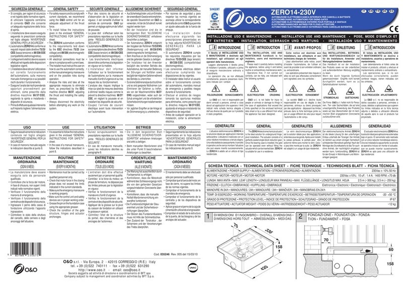
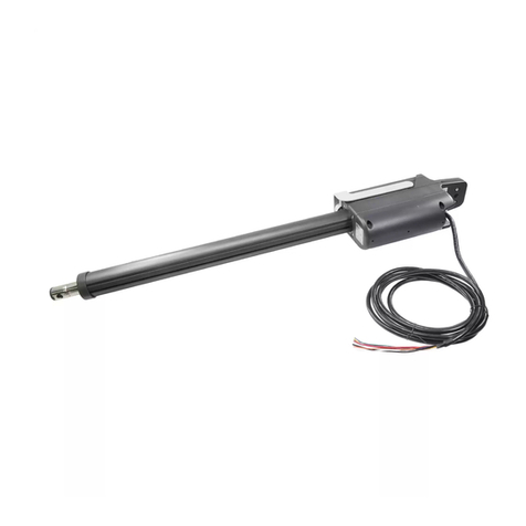
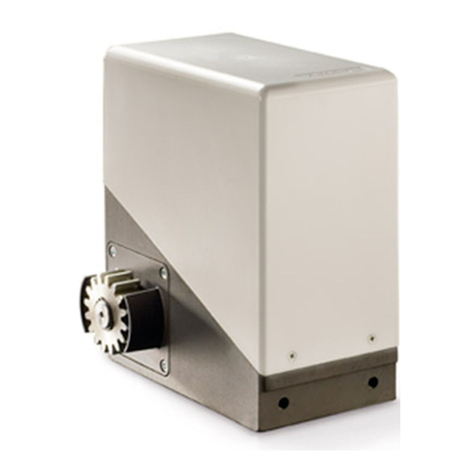
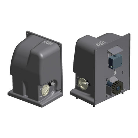
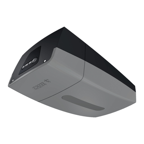
Stagnoli ULIXES User manual

Istruzioni , Instructions, Betriebsanleitung, , Instrucciones
1
I - Motoriduttore elettromeccanico per cancelli battenti
GB - The electromechanical gear motor for swing gates
F - Motoréducteur électromécanique pour portails battants
D - Elektromechanisches Getriebe für Flügeltore
E - Motorreductor electromecánico para portones de batiente
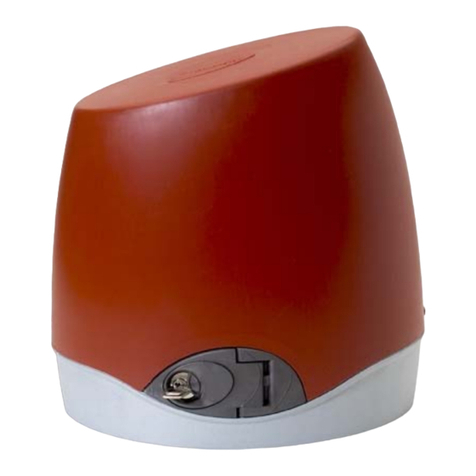
ULIXES

Istruzioni , Instructions, Betriebsanleitung, , Instrucciones
4
Il presente manuale è destinato solamente al personale tecnico qualificato per
l’installazione e non all’utilizzatore finale; è compito dell’installatore informare
successivamente l’utilizzatore, sulle modalità d’uso dell’automatismo, sui possibili pericoli
che ne possono derivare e sulla necessità di una manutenzione periodica.
L’installazione deve essere effettuata solo da personale qualificato e rispettando le
vigenti normative riguardanti le chiusure automatizzate.
ULIXES è stato realizzato appositamente per gestire l’automazione di cancelli a battenti,
quindi, è vietato utilizzare il prodotto per scopi diversi da quelli previsti o in modo
improprio.
Utilizzare componenti originali. La ditta Stagnoli non si assume alcuna responsabilità per
danni dovuti all’utilizzo di componenti non originali.
Accertarsi che la struttura del cancello sia solida e adatta ad essere motorizzata.
Accertarsi che il cancello durante il suo movimento non subisca punti di attrito, ne abbia
la possibilità di deragliare .
Prima di intervenire sul dispositivo, assicurarsi che l’alimentazione sia staccata.
Collegare il cavo della tensione solo a linee di alimentazione dotate di adeguate
protezioni elettriche.
Valutare con particolare attenzione i dispositivi di sicurezza da installare ed il luogo in cui
devono essere posizionati, inoltre, inserire sempre un dispositivo di arresto di emergenza
che permetta il distacco obbligato dell’alimentazione.
L’irreversibilità del motoriduttore evita l’installazione di elettroserrature e in caso di black-
out, il dispositivo di sblocco, protetto da chiave personalizzata, permette al cancello di
essere aperto e chiuso manualmente. L’utilizzo dell’elettroserratura è comunque
consigliato per assicurare una chiusura più efficace, soprattutto nel caso di battenti di
lunghezza superiore ai 2.5 metri.

Istruzioni , Instructions, Betriebsanleitung, , Instrucciones
5
Caratteristiche tecniche Ulixes
Dati tecnici ULIXES 230V ULIXES 24V
Alimentazione 230V~ (50Hz) 230V~ (50Hz)
Corrente assorbita max. (A) 1,3 1
Alimentazione motore 230V~ 24V –––––
Potenza motore max. 160 W 120 W
Condensatore 10 F -
Corsa di lavoro (mm)* 350 – 500 350 – 500
Tempo corsa* (sec) 15 - 25 15 - 25
Velocità (rpm) 1400 - 900 1100
Rapporto di riduzione 1/24 1/24
Max. angolo di apertura 115° 115°
Temperatura operativa (°C) -20 +60 -20 +60
Termoprotezione (°C) 150 -
Ciclo di lavoro residenziale intensivo
Livello di protezione IP 44 44
Peso* (Kg) 9 9
N.B : La corsa di lavoro, la lunghezza dell’automazione, e il peso dipendono dal modello di
ULIXES utilizzato.
960
118
139
Corsa 500
139
118
Corsa 350
Ulixes 350
Ulixes 500
810

Istruzioni , Instructions, Betriebsanleitung, , Instrucciones
6
Limiti di impiego
ANTA 2 m 2.5 m 3 m 3.5 m 4 m 4.5 m 5 m
300 kg
ULIXES
350
ULIXES
350
ULIXES
350
ULIXES
350
ULIXES
500
ULIXES
500
ULIXES
500
400 kg
ULIXES
350
ULIXES
350
ULIXES
350
ULIXES
500
ULIXES
500
500 kg ULIXES
350
ULIXES
350
ULIXES
500
ULIXES
500
600 kg ULIXES
350
ULIXES
350
ULIXES
500
700 kg ULIXES
350
ULIXES
500
800 kg ULIXES
350
ULIXES
500
900 kg ULIXES
500
1000 kg ULIXES
500
Sblocco manuale
1) Scorrere in avanti il copri serratura
2) Ruotare la chiave
3) Tirare la maniglia, fino a portarla perpendicolare al motore
90°
0°
3
2
1

Istruzioni , Instructions, Betriebsanleitung, , Instrucciones
7
Verifiche preliminari
Prima di procedere con l’installazione di Ulixes verificare i punti seguenti:
Controllare che la struttura del cancello sia sufficientemente robusta e che non ci siano punti di
attrito.
Controllare che le cerniere del cancello siano efficienti e siano adeguatamente lubrificate.
Verificare che ci sia un fermo meccanico d’arresto in chiusura.
Verificare la dimensione della quota “C”prima dell’installazione, attenendosi alle specifiche della
tabella di montaggio (tab.1).
Aumentando il valore della quota “B”si riduce l’angolo di apertura, la velocita’ periferica e
aumenta la spinta motore sull’anta ; diversamente accrescendo “A”aumenta l’angolo di
apertura, la velocita’ periferica e si riduce la spinta motore sull’anta.
C
A
B
D
Apertura
A
B
APERTURA A B C D
Corsa 350 90 140 140 60 570
Corsa 350 115 160 150 40 550
Corsa 500 90 140 140 60 720
Corsa 500 115 160 150 40 700
Tab.1

Istruzioni , Instructions, Betriebsanleitung, , Instrucciones
8
Fissaggio delle staffe al pilastro e al cancello
Dopo aver verificato le condizioni ottimali per il collocamento delle piastre e il relativo
allineamento, fissarle al pilastro e al cancello in modo definitivo, saldandole o utilizzando dei
tasselli ad espansione (in caso di pilastro in muratura), rispettando la quota specificata nella
figura 2.
Bordo inferiore della
staffa fissata all'anta
28
Bordo inferiore della
staffa fissata al pilastro
Fissaggio del motoriduttore
Bloccare il motoriduttore posteriormente con la vite esagonale M8 e relativo dado e rosetta (fig.3).
Fig.3
Posizionare la madrevite sul perno della staffa anteriore e avvitare la vite trasversale per bloccarla nella
posizione di lavoro (fig. 4).
Fig.4

Istruzioni , Instructions, Betriebsanleitung, , Instrucciones
9
Collegamenti elettrici ULIXES 230V: Con il motore fissato al cancello, eseguire i collegamenti
elettrici come specificato nella fig.5. Per ulteriori specifiche consultare gli schemi di collegamento alla
centrale.
(Azzurro)
Comune
ondensatoreC
alla centralina
Cavo di collegamento
Fase (MARRONE)
+
Cavo condensatore
Cavo condensatore
+
Fase (NERO)
Messa a Terra
(GIALLO / VERDE)
Fig.5
Collegamenti elettrici ULIXES 24V: Con il motore fissato al cancello, eseguire i collegamenti elettrici
come specificato nella fig.6. Per ulteriori specifiche consultare gli schemi di collegamento alla centrale.
Cavo di collegamento
ENC_ (arancio)
APM (rosso)
CHM (blu)
(2x2.5mm2 + 1x0.5mm2)
Fig.6

Istruzioni , Instructions, Betriebsanleitung, , Instrucciones
10
Attention!
This manual is for qualified installers only and not for the end user. It is the installer’s job to
explain to the user how the automatism works, about possible hazards related to it and
the need for periodical maintenance.
Installation must be carried out by qualified personnel only, in compliance with current
standards concerning automatic closing mechanisms.
ULIXES is made specifically to control the automation of swing gates and therefore it is
forbidden to use it for any other purposes or improperly.
Use original components only. Stagnoli is not liable for damages if any other components
are used.
Make sure that the gate structure is solid and suitable to be motorised.
Make certain that when the gate is moving there are no points of friction and there is no
chance of it derailing.
Make absolutely certain the power is disconnected before carrying out any work on the
device.
Connect the power lead only to supply lines with adequate electrical protection.
Be particularly careful when evaluating the safety devices to install and their location.
Always install an emergency stop device that will cut power off in the case of necessity.
The irreversible gearmotor avoids installing an electric lock and in case of black-out the
release with personal single key allows the gate to be easily opened and closed.
Nevertheless the electronic lock should be installed to assure a better closing above all
by wings longer than 2.5 meters.

Istruzioni , Instructions, Betriebsanleitung, , Instrucciones
11
Ulixes technical features
Technical data ULIXES 230V ULIXES 24V
Supply power 230V~ (50Hz) 230V~ (50Hz)
Max. Input current (A) 1.3 1
Motor power supply 230V~ 24V –––––
Max. Motor power (W) 160 W 120 W
Capacitor 10 F -
Working travel (mm)* 350 – 500 350 – 500
Travel time* (sec) 15 - 25 15 - 25
Rpm 1400 - 900 1100
Reduction ratio 1/24 1/24
Max. openinig angle 115° 115°
Working temperature (°C) -20 +60 -20 +60
Thermal overload protection (°C) 150 -
Work cycle residential intensive
IP protection level 44 44
Weight* (Kg) 9 9
Note: working travel, the length of the automation and weight depend on the ULIXES model
used. Overall dimensions
960
118
139
Corsa 500
139
118
Corsa 350
Ulixes 350
Ulixes 500
810

Istruzioni , Instructions, Betriebsanleitung, , Instrucciones
12
Limits of use
LEAF 2 m 2.5 m 3 m 3.5 m 4 m 4.5 m 5 m
300 kg
ULIXES
350
ULIXES
350
ULIXES
350
ULIXES
350
ULIXES
500
ULIXES
500
ULIXES
500
400 kg
ULIXES
350
ULIXES
350
ULIXES
350
ULIXES
500
ULIXES
500
500 kg ULIXES
350
ULIXES
350
ULIXES
500
ULIXES
500
600 kg ULIXES
350
ULIXES
350
ULIXES
500
700 kg ULIXES
350
ULIXES
500
800 kg ULIXES
350
ULIXES
500
900 kg ULIXES
500
1000 kg ULIXES
500
Releasing manually
1. Slide the lock cover forwards
2. Turn the key
3. Pull the handle until it is perpendicular to the motor
90°
0°
3
2
1

Istruzioni , Instructions, Betriebsanleitung, , Instrucciones
13
Preliminary checks
Check the following points before commencing to install Ulixes:
Check that the gate structure is sufficiently robust and there are no points of friction.
Check the condition of the gate hinges; make sure they are adequately lubricated.
Check there is a mechanical stop in closing.
Check value “C”before installing, observing the specifications in the assembly table (tab.1).
By increasing value “B” the opening angle is reduced, peripheral speed and the thrust of the motor on
the gate is increased; to the contrary, by increasing “A” the opening angle is increased, peripheral speed
and the thrust of the motor on the gate is reduced.
DA
B
Opening
A
B
C
OPENING A B C D
Travel 350 90 140
140
60 570
Travel 350 115 160
150
40 550
Travel 500 90 140
140
60 720
Travel 500 115 160
150
40 700
Tab.1

Istruzioni , Instructions, Betriebsanleitung, , Instrucciones
14
Fixing the brackets to the post and gate
After having verified the optimum conditions for placing the plates and their alignment, fix them to the
post and gate permanently, either welding them or utilising expansion bolts (if the post is made of brick),
observing the value specified in Fig. 2.
28
Bottom edge of the
bracket fixed to the gate
Bottom edge of the
bracket fixed to the post
Fig.2
Fixing the gear motor
Lock the gear motor at the back with the M8 hex head screw with nut and washer (Fig.3).
Fig.3
Fit the nut screw on the front bracket pin and tighten the traverse screw to lock it in the working position
(Fig. 4).
Fig. 4

Istruzioni , Instructions, Betriebsanleitung, , Instrucciones
15
ULIXES 230V electrical connections : with the motor already fixed to the gate, wire as shown in Fig.
5. For more specifications please see the diagrams for connecting to the control unit.
(light blue)
Common
Capacitor
Wire connecting to the control unit
Phase (brown)
+ capacitor cable
Phase (black)
+ capacitor cable
Ground
(yellow-green)
Fig.5
ULIXES 24V electrical connections : with the motor already fixed to the gate, wire as shown in Fig.
6. For more specifications please see the diagrams for connecting to the control unit
CONNECTION CABLE
ENC_ (orange)
APM (red)
CHM (blue)
(2x2.5mm2 + 1x0.5mm2)
Fig. 6

Istruzioni , Instructions, Betriebsanleitung, , Instrucciones
16
Attention !
Le présent manuel n’est destiné qu’à du personnel technique qualifié et non pas à
l’utilisateur final ; c’est l’installateur qui doit fournir à l’utilisateur toutes les explications
nécessaires à propos des modalités d’utilisation de l’automatisme et des dangers
pouvant dériver de cette utilisation et l’avertir de la nécessité d’effectuer une
maintenance périodique.
L’installation ne doit être effectuée que par du personnel qualifié et dans le respect des
normes en vigueur en ce qui concerne les fermetures automatisées.
ULIXES a été conçu pour la gestion de portails battants, ne pas utiliser le produit dans un
but différent de celui prévu ou de manière inappropriée.
N’utiliser que des composants originaux. L’entreprise Stagnoli ne s’assume aucune
responsabilité pour des dommages provoqués par l’emploi de composants non
originaux.
Vérifier si la structure du portail est solide et si elle peut être motorisée.
Vérifier si le portail ne présente aucun point de friction pendant le mouvement et s’il n’a
aucune possibilité de dérailler.
Avant d’intervenir sur le dispositif s’assurer que l’alimentation est bien débranchée.
Ne brancher le câble d’alimentation qu’à des lignes d’alimentation avec des protections
électriques adéquates.
Evaluer avec une attention particulière les dispositifs de sécurité à installer et l’endroit de
leur mise en place, en outre il faut prévoir un dispositif d’arrêt d’urgence permettant la
coupure obligatoire de l’alimentation.
L’irréversibilité du motoréducteur évite l’installation de la serrure électrique et en cas de
black-out le déverrouillage avec clé personnalisé permet l’ouverture et la fermeture
manuelle du portail. De toute façon on conseil l’installation de la serrure électrique afin
d’assurer une fermeture plus efficace surtout dans le cas de volets de longueur
supérieure à 2.5 mètres.

Istruzioni , Instructions, Betriebsanleitung, , Instrucciones
17
Caractéristiques techniques Ulixes
Données techniques ULIXES 230V ULIXES 24V
Alimentation 230V~ (50 Hz) 230V~ (50 Hz)
Courant absorbé max. (A) 1,3 1
Alimentation moteur. 230V~ 24V –––––
Puissance moteur max (W) 160 W 120 W
Condensateur 10 F -
Cycle de travail (mm)* 350 – 500 350 – 500
Temps course* (sec) 15 - 25 15 - 25
Vitesse (rpm) 1400 - 900 1100
Rapport de réduction 1/24 1/24
Max. Overture 115° 115°
Température opérationnelle (°C) -20 +60 -20 +60
Protection thermique (°C) 150 -
Cycle de travail residentiel intensif
Niveau de protection IP 44 44
Poids (Kg) 9 9
N.B : La course de travail, la longueur de l’automation, et le poids dépendent du modèle
d’ULIXES utilisé. Mesures d’encombrement
960
118
139
Corsa 500
139
118
Corsa 350
Ulixes 350
Ulixes 500
810

Istruzioni , Instructions, Betriebsanleitung, , Instrucciones
18
Limites d’emploi
BATTANT 2 m 2.5 m 3 m 3.5 m 4 m 4.5 m 5 m
300 Kg
ULIXES
350
ULIXES
350
ULIXES
350
ULIXES
350
ULIXES
500
ULIXES
500
ULIXES
500
400 Kg
ULIXES
350
ULIXES
350
ULIXES
350
ULIXES
500
ULIXES
500
500 Kg ULIXES
350
ULIXES
350
ULIXES
500
ULIXES
500
600 Kg ULIXES
350
ULIXES
350
ULIXES
500
700 Kg ULIXES
350
ULIXES
500
800 Kg ULIXES
350
ULIXES
500
900 Kg ULIXES
500
1000 Kg ULIXES
500
Déblocage manuel
1. Faire glisser en avant les couvre-serrures
2. Tourner la clé
3. Tirer la poignée, jusqu’à la mettre en position perpendiculaire par rapport au moteur
90°
0°
3
2
1

Istruzioni , Instructions, Betriebsanleitung, , Instrucciones
19
Contrôles préliminaires
Avant d’effectuer l’installation d’Ulixes vérifier les points suivants:
Contrôler si la structure du portail est suffisamment robuste et s’il n’y a aucun point de friction.
Contrôler si les charnières du portail sont efficientes et lubrifiées de manière appropriée.
Vérifier s’il y a un cran mécanique d’arrêt en fermeture.
Vérifier la dimension de la partie “C”avant l’installation, en respectant les spécifiques du tableau
de montage (tab.1).
B
A
Apertura
D
B
A
C
Fig.1
OUVERTURE A B C D
Course 350 90 140
140
60 570
Course 350 115 160
150
40 550
Course 500 90 140
140
60 720
Course 500 115 160
150
40 700
Tab.1

Istruzioni , Instructions, Betriebsanleitung, , Instrucciones
20
Fixation des étriers au pilier et au portail
Après avoir recherché les conditions optimales d’installation des plaques ainsi que l’alignement, les fixer
au pilier et au portail de manière définitive, en les soudant ou en utilisant les chevilles d’expansion (en cas
de pilier en maçonnerie), en respectant la mesure spécifiée dans la figure (fig. 2).
28
Bord inférieur de
la bride du volet
Bord inférieur de
la bride du pilier
Fig.2
Installation du motoréducteur
Bloquer le motoréducteur à l’arrière avec la vis à six pans M8 et l’écrou et la rondelle correspondante
(fig.3).
Fig.3
Mettre la vis mère sur le pivot de l’étrier avant et visser la vis transversale pour la bloquer en position de
travail (fig. 4).
Fig.4
This manual suits for next models
2
Table of contents
Languages:
Other Stagnoli Gate Opener manuals


