Reihe 8602/3
Series 8602/3
Subject to alterations.
Änderungen vorbehalten.
1 Sicherheit
Das Gerät wurde nach dem aktuellen Stand der Technik unter
anerkannten sicherheitstechnischen Regeln hergestellt. Dennoch
können bei seiner Verwendung Gefahren für Leib und Leben des
Benutzers oder Dritter bzw. eine Beeinträchtigung des Geräts,
der Umwelt und von Sachwerten entstehen.
▶
Für die hier beschriebenen Tätigkeiten ist eine entsprechend
qualifizierte Fachkraft erforderlich. Diese Fachkräfte müssen einen
Kenntnisstand haben, der relevante nationale Normen und
Bestimmungen umfasst. Für Tätigkeiten in explosionsgefährdeten
Bereichen sind weitere Kenntnisse erforderlich (siehe Handbuch)!
▶
Montage, Installation, Inbetriebnahme und Wartung nur unter
Beachtung des Handbuchs vornehmen!
Insbesondere Kapitel 3 ("Sicherheit") des Handbuchs beachten!
▶
Gerät nur in unbeschädigtem Zustand, bestimmungsgemäß,
sicherheits- und gefahrenbewusst einsetzen!
▶
Bei Betriebsbedingungen, die von den technischen Daten
abweichen, bei der R. STAHL Schaltgeräte GmbH rückfragen!
1.1 Bestimmungsgemäße Verwendung
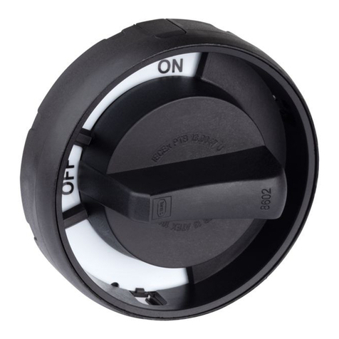
Die Betätigungsvorsätze 8602/3 sind für den Einsatz in explosions-
gefährdeten Bereichen der Zonen 1, 2, 21 und 22 und im sicheren
Bereich zugelassen.
Sie sind zum Einbau in Gehäusewände und -deckel elektrischer
Betriebsmittel bzw. von Schalttafeln der Zündschutzart Erhöhte
Sicherheit "Ex e" und Schutz durch Gehäuse "Ex tb" vorgesehen.
Je nach Typ werden sie zur Signalmeldung, zur Überwachung und
Steuerung oder auch zum Not-Halt elektrischer Betriebsmittel
eingesetzt.
2 Montage und Installation
2.1 Einbaubedingungen
▶
Betätigungsvorsätze nur bis zu einer Wandstärke von
5 mm / 0.197 in, Drehgriffe mit radialem Antrieb nur bis zu einer
Wandstärke von 3 mm / 0.118 in einbauen.
▶
Betätigungsvorsätze nicht mit LED-Leuchtmeldern
(Reihe 8010/x-xx-ws) verwenden.
▶
Betätigungsvorsätze in NEC-Ausführung nur mit speziellem
Sonderzubehör einsetzen, siehe Handbuch, Kapitel 5.1.8 und 5.1.9.
2.2 Montage Betätigungsvorsatz
▶
Auf einen korrekten Sitz der Dichtung (4) achten.
▶
Betätigungsvorsatz (5) zum Stanzbild in der Einbauwand (3)
ausrichten.
▶
Gegenmutter (2) mit Spezialschlüssel (1) anziehen
(Anzugsdrehmoment 3 Nm / 26.55 lbf-in).
Fronteinbau mit Einbauelementen
▶
Adapter (30) auf den Betätigungsvorsatz (5) aufsetzen.
▶
Adapter (30) im Uhrzeigersinn drehen, bis er hörbar arretiert ist.
▶
Adapter (30) auf festen Sitz prüfen.
▶
Einbauelement(e) (31) auf den Adapter aufrasten.
Es können max. 3 Einbauelemente aufgerastet werden.
3 Inbetriebnahme
Vor Inbetriebnahme folgende Prüfschritte durchführen:
▶
Kontrollieren, ob Montage und Installation vorschriftsmäßig
ausgeführt wurden.
▶
Betätigungsvorsätze auf Schäden prüfen.
▶
Prüfen, ob alle vorgeschriebenen Anzugsdrehmomente eingehalten
sind.
▶
Kontrollieren, ob Betätigungsvorsatz die geforderte Funktion erfüllt.
▶
Kontrollieren, ob die Dichtung korrekt sitzt.
4 Instandhaltung, Wartung, Reparatur
▶
Geltende nationale Normen und Bestimmungen im Einsatzland
beachten.
4.1 Instandhaltung
Ergänzend zu den nationalen Regeln folgende Punkte prüfen:
• Rissbildung und andere sichtbare Schäden am Gerät,
• festen Sitz der Befestigungen,
• für Schließzylinder nur CES-Pflegemittel verwenden.
• Kontrollieren, ob Betätigungsvorsatz die geforderte Funktion erfüllt.
4.2 Wartung
▶
Gerät gemäß den geltenden nationalen Bestimmungen und den
Sicherheitshinweisen des Handbuchs (Kapitel "Sicherheit") warten.
4.3 Reparatur
▶
Reparaturen am Gerät nur durch R. STAHL durchführen lassen.
5 Entsorgung
▶
Nationale und lokal gültige Vorschriften und gesetzliche
Bestimmungen zur Entsorgung beachten.
▶
Materialien getrennt dem Recycling zuführen.
▶
Umweltgerechte Entsorgung aller Bauteile gemäß den gesetzlichen
Bestimmungen sicherstellen.
6 Technische Daten
Weitere technische Daten, siehe Handbuch und r-stahl.com.
1 Safety
The device has been manufactured according to the state of the
art of technology while observing recognised safety-related rules.
When using the device, it is nevertheless possible for hazards to occur
to life and limb of the user or third parties or for the device, environment
or material assets to be compromised.
▶
Qualified specialist personnel are required to perform the activities
described here. These specialists must have a level of knowledge
that meets applicable national standards and regulations.
Additional knowledge is required for any activity in hazardous areas
(see manual).
▶
Only perform mounting, installation, commissioning and
maintenance in accordance with the manual.
Note chapter 3 ("Safety") of the manual in particular.
▶
Only use the device in an undamaged state in accordance with its
intended use, taking into account safety and hazards.
▶
Consult with R. STAHL Schaltgeräte GmbH if operating conditions
deviate from the technical data.
1.1 Intended use
The 8602/3 actuators are approved for use in hazardous areas of
Zones 1, 2, 21 and 22 and in safe areas.
They are intended for installation in enclosure walls and enclosure
covers of electrical equipment or of panels with the increased safety
"Ex e" and protection by enclosure "Ex tb" type of protection.
Depending on the type, they are used for signal messages,
for monitoring and control or even for emergency stopping electrical
equipment.
2 Mounting and installation
2.1 Installation conditions
▶
Only install actuators up to a wall thickness of 5 mm/0.197 in,
and rotary actuators with radial drive only up to a wall thickness of
3 mm/0.118 in.
▶
Do not use actuators with LED indicator lamps
(series 8010/x-xx-ws).
▶
Only use actuators in NEC version with particular special
accessories, see manual, chapter 5.1.8 and 5.1.9.
2.2 Actuator mounting
▶
Ensure correct fit of the seal (4).
▶
Align the actuator (5) with the punch pattern in the installation
wall (3).
▶
Tighten the jam nut (2) with the special wrench (1)
(tightening torque 3 Nm/26.55 lbf-in).
Front installation with built-in elements
▶
Connect the adaptor (30) to the actuator (5).
▶
Turn the adaptor (30) clockwise until it audibly snaps into place.
▶
Check that the adaptor (30) fits securely.
▶
Snap the built-in element(s) (31) onto the adaptor.
A maximum of 3 built-in elements can be snapped on.
3 Commissioning
Before commissioning, carry out the following checks:
▶
Check whether the mounting and installation have been executed
according to regulations.
▶
Check the actuators for damage.
▶
Check whether all the specified tightening torques have been
observed.
▶
Check whether the actuator fulfills the required function.
▶
Check whether the seal fits correctly.
4 Maintenance, overhaul, repair
▶
Observe the relevant national standards and regulations in the
country of use.
4.1 Maintenance
Check the following points in addition to the national regulations:
• Whether the device has cracks or other visible signs of damage
• Whether the parts are securely fitted
• Use only CES care products for locking cylinders.
• Check whether the actuator fulfills the required function.
4.2 Overhaul
▶
Perform overhaul of the device according to the applicable national
regulations and the safety notes in the manual ("Safety" chapter).
4.3 Repair
▶
Repair work on the device must be performed only by R. STAHL.
5 Disposal
▶
Observe national, local and statutory regulations regarding disposal.
▶
Separate materials for recycling.
▶
Ensure environmentally friendly disposal of all components
according to statutory regulations.
6 Technical data
For further technical data, see manual and r-stahl.com.
GEFAHR! Explosionsgefahr durch zu starke oder fehlerhafte
Abdichtung des Geräts!
Nichtbeachten führt zu tödlichen oder schweren Verletzungen.
▶
Vorgegebene (maximale) Gehäusewandstärken einhalten.
▶
Gerät anhand der Maßzeichnungen
(siehe Handbuch, Kapitel "Anhang B") einbauen.
Auf sorgfältige Einhaltung der Maße achten.
▶
Vorgegebene Anzugsdrehmomente einhalten.
17578E00
21795E00
Legende
1 = Spezialschlüssel (Art. Nr. 169101)
2 = Gegenmutter (Art. Nr. 205592)
3 = Einbauwand (Wandstärke max. 5 mm / 0.197 in)
4 = Dichtung
5 = Betätigungsvorsatz
30 = Adapter (Art. Nr. 227038)
31 = Einbauelemente
Zur Montage der Bedien-Komponenten (Druckplatten, Tasten-
schild, Farbfilter, Farbkappe, Drehvorsätze und Zubehör)
siehe Handbuch.
Explosionsschutz
Global (IECEx)
Gas und
Staub IECEx PTB 13.0047U
Ex eb IIC Gb
Ex tb IIIC Db
Europa (ATEX)
Gas und
Staub PTB 13 ATEX 1019 U
E II 2 G Ex eb IIC Gb
E II 2 D Ex tb IIIC Db
USA (NEC)/Kanada (CEC)
NEC und
CEC E182378
NEC:
Class I, Zone 1, AEx eb IIC Gb
Zone 21, AEx tb IIIC Db
CEC:
Ex eb IIC Gb U
Ex tb IIIC Db
Bescheinigungen und Zertifikate
Bescheini-
gungen IECEx, ATEX, USA (NEC), Kanada (CEC)
Technische Daten
Umgebungsbedingungen
Betriebs-
temperatur Silikonfrei (NBR) -20 ... +60 °C / -4 ... +140 °F
Silikon: -60 ... +70 °C / -76 ... +158 °F
Verwendung
in Höhe < 2000 m
Mechanische Daten
Material Polyamid
Schutzart IP66 gemäß IEC/EN 60529
Verschmut-
zungsgrad 3
Maße siehe Handbuch
DANGER! Explosion hazard due to the sealing of the device
being too strong or defective.
Non-compliance results in fatal or severe injuries.
▶
Observe the specified (maximum) enclosure wall
thicknesses.
▶
Install the device based on the dimensional drawings
(see manual, chapter "Appendix B").
Ensure that the dimensions are carefully observed.
▶
Observe specified tightening torques.
17578E00
21795E00
Legend
1 = special wrench (item no. 169101)
2 = jam nut (item no. 205592)
3 = installation wall (wall thickness max. 5 mm/0.197 in)
4 = seal
5 = actuator
30 = adaptor (item no. 227038)
31 = built-in elements
For mounting of the operating components (pressure plates,
button label, colour filter, colour cap, rotational actuators and
accessories), see manual.
Explosion protection
Global (IECEx)
Gas and dust IECEx PTB 13.0047U
Ex eb IIC Gb
Ex tb IIIC Db
Europe (ATEX)
Gas and dust PTB 13 ATEX 1019 U
E II 2 G Ex eb IIC Gb
E II 2 D Ex tb IIIC Db
USA (NEC)/Canada (CEC)
NEC and
CEC E182378
NEC:
Class I, Zone 1, AEx eb IIC Gb
Zone 21, AEx tb IIIC Db
CEC:
Ex eb IIC Gb U
Ex tb IIIC Db
Certifications and certificates
Certifications IECEx, ATEX, USA (NEC), Canada (CEC)
Technical data
Ambient conditions
Service
temperature Silicone-free
(NBR) -20 to +60 °C/-4 to +140 °F
Silicone: -60 to +70 °C/-76 to +158 °F
Use at height < 2000 m
Mechanical data
Material Polyamide
Degree of
protection IP66 according to IEC/EN 60529
Degree of
pollution 3
Dimensions See manual
