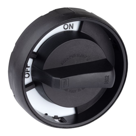
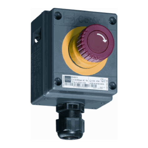
Stahl 8602/1 Series User manual

DE
DE
DE
DE
DE
DE
DE
DE
DE
DE
DE
DE
DE
DE
DE
DE
DE
DE
DE
DE
DE
DE
DE
DE
DE
Umbauanleitung
Additional languages www.stahl-ex.com
DE
Umbausatz für Betätigungsvorsatz
Reihe 8602/1

Allgemeine Angaben
2261661 / 8602620300
2017-06-01·BA00·III·de·00
Umbausatz für Betätigungsvorsatz
Reihe 8602/1
DE
DE
DE
DE
DE
DE
DE
DE
DE
DE
DE
DE
DE
DE
DE
DE
DE
DE
DE
DE
DE
DE
DE
DE
DE
Inhaltsverzeichnis
1 Allgemeine Angaben ...........................................................................................2
1.1 Hersteller .............................................................................................................2
1.2 Angaben zur Umbauanleitung ............................................................................2
1.3 Konformität zu Normen und Bestimmungen .......................................................2
2 Erläuterung der Symbole ....................................................................................3
2.1 Symbole in der Umbauanleitung .........................................................................3
2.2 Warnhinweise .....................................................................................................3
2.3 Symbole am Gerät ..............................................................................................3
3 Sicherheit ............................................................................................................4
4 Sicherheitshinweise ............................................................................................4
4.1 Aufbewahrung der Umbauanleitung ...................................................................4
4.2 Sichere Verwendung ...........................................................................................4
4.3 Umbauten und Änderungen ................................................................................4
5 Bestimmungsgemäße Verwendung ....................................................................5
6 Montage / Demontage, Gebrauchslage ..............................................................5
7 Entsorgung ..........................................................................................................7
8 Zubehör und Ersatzteile .....................................................................................7
1 Allgemeine Angaben
1.1 Hersteller
R. STAHL Schaltgeräte GmbH
Am Bahnhof 30
74638 Waldenburg
Germany
Tel.: +49 7942 943-0
Fax: +49 7942 943-4333
Internet: www.stahl-ex.com
E-Mail: [email protected]
1.2 Angaben zur Umbauanleitung
ID-Nr.: 261661 / 8602620300
Publikationsnummer: 2017-06-01·BA00·III·de·00
1.3 Konformität zu Normen und Bestimmungen
Siehe Zertifikate und EU-Konformitätserklärung: www.stahl-ex.com.

261661 / 8602620300
2017-06-01·BA00·III·de·00
Erläuterung der Symbole
3
Umbausatz für Betätigungsvorsatz
Reihe 8602/1
DE
DE
DE
DE
DE
DE
DE
DE
DE
DE
DE
DE
DE
DE
DE
DE
DE
DE
DE
DE
DE
DE
DE
DE
DE
2 Erläuterung der Symbole
2.1 Symbole in der Umbauanleitung
2.2 Warnhinweise
Warnhinweise unbedingt befolgen, um das konstruktive und durch den Betrieb bedingte
Risiko zu minimieren. Die Warnhinweise sind wie folgt aufgebaut:
• Signalwort: GEFAHR, WARNUNG, VORSICHT, HINWEIS
• Art und Quelle der Gefahr/des Schadens
• Folgen der Gefahr
• Ergreifen von Gegenmaßnahmen zum Vermeiden der Gefahr/des Schadens
2.3 Symbole am Gerät
Symbol Bedeutung
Tipps und Empfehlungen zum Gebrauch des Geräts
Gefahr durch explosionsfähige Atmosphäre
GEFAHR
Gefahren für Personen
Nichtbeachtung der Anweisung führt zu schweren oder tödlichen
Verletzungen bei Personen.
WARNUNG
Gefahren für Personen
Nichtbeachtung der Anweisung kann zu schweren oder tödlichen
Verletzungen bei Personen führen.
VORSICHT
Gefahren für Personen
Nichtbeachtung der Anweisung kann zu leichten Verletzungen bei Personen
führen.
HINWEIS
Vermeidung von Sachschaden
Nichtbeachtung der Anweisung kann zu einem Sachschaden am Gerät und/oder seiner
Umgebung führen.
Symbol Bedeutung
16338E00
ATEX-benannte Stelle für Qualitätsüberwachung.
02198E00
Gerät gemäß Kennzeichnung für explosionsgefährdete Bereiche zertifiziert.

Sicherheit
4261661 / 8602620300
2017-06-01·BA00·III·de·00
Umbausatz für Betätigungsvorsatz
Reihe 8602/1
DE
DE
DE
DE
DE
DE
DE
DE
DE
DE
DE
DE
DE
DE
DE
DE
DE
DE
DE
DE
DE
DE
DE
DE
DE
3 Sicherheit
Für die in dieser Umbauanleitung beschriebenen Tätigkeiten ist eine entsprechend
qualifizierte Fachkraft erforderlich. Dies gilt vor allem für Arbeiten in den Bereichen
• Produktauswahl, Projektierung und Modifikation
• Montage/Demontage des Geräts
• Installation
• Inbetriebnahme
• Instandhaltung, Reparatur, Reinigung
Fachkräfte, die diese Tätigkeiten ausführen, müssen einen Kenntnisstand haben,
der relevante nationale Normen und Bestimmungen umfasst.
Für Tätigkeiten in explosionsgefährdeten Bereichen sind weitere Kenntnisse
erforderlich! R. STAHL empfiehlt einen Kenntnisstand, der in folgenden Normen
beschrieben wird:
•IEC/EN 60079-14 (Projektierung, Auswahl und Errichtung elektrischer Anlagen)
•IEC/EN 60079-17 (Prüfung und Instandhaltung elektrischer Anlagen)
•IEC/EN 60079-19 (Gerätereparatur, Überholung und Regenerierung)
4 Sicherheitshinweise
4.1 Aufbewahrung der Umbauanleitung
• Umbauanleitung sorgfältig lesen und am Einbauort des Geräts aufbewahren.
• Mitgeltende Dokumente und Betriebsanleitungen der anzuschließenden Geräte
beachten.
4.2 Sichere Verwendung
Beachten Sie Folgendes bei Installation und Betrieb:
- Beschädigungen können den Explosionsschutz aufheben
- Nationale und örtliche Sicherheitsvorschriften
- Nationale und örtliche Unfallverhütungsvorschriften
- Nationale und örtliche Montage- und Errichtungsvorschriften
- Allgemein anerkannte Regeln der Technik
- Sicherheitshinweise dieser Umbauanleitung
- Kennwerte und Bemessungsbetriebsbedingungen der Typ- und Datenschilder
- Zusätzliche Hinweisschilder auf dem Gerät
• Umlaufende Dichtung nicht beschädigen.
4.3 Umbauten und Änderungen
GEFAHR
Explosionsgefahr durch zweckentfremdete Verwendung!
Nichtbeachten führt zu schweren oder tödlichen Verletzungen.
• Gerät ausschließlich entsprechend den in dieser Umbauanleitung
festgelegten Betriebsbedingungen verwenden.
261661 / 8602620300
2017-06-01·BA00·III·de·00
Bestimmungsgemäße Verwendung
5
Umbausatz für Betätigungsvorsatz
Reihe 8602/1
DE
DE
DE
DE
DE
DE
DE
DE
DE
DE
DE
DE
DE
DE
DE
DE
DE
DE
DE
DE
DE
DE
DE
DE
DE
5 Bestimmungsgemäße Verwendung
Diese Umbauanleitung beschreibt den ordnungsgemäßen Umbau des
Betätigungsvorsatzes 8602/1.
6 Montage / Demontage, Gebrauchslage
Vorgehensweise beim Umbau des Betätigungsvorsatzes:
19426E00
1. Spezialschlüssel
2. Platte (rot, schwarz)
3. Gegenmutter
4. Dichtung (zwei Stück beiliegend. Die zweite Dichtung
wird bei der Verwendung von Schutzkragen oder
Abschließvorrichtung benötigt)
5. Betätigungsvorsatz
Demontage
Schritt 1: Schritt 2: Schritt 3:
19427E00 19428E00
19429E00
• Platte (2) lösen. • Gegenmutter (3)
mittels
Spezialschlüssel (1)
lösen.
• Betätigungsvorsatz (5)
entfernen.
5

Montage / Demontage, Gebrauchslage
6261661 / 8602620300
2017-06-01·BA00·III·de·00
Umbausatz für Betätigungsvorsatz
Reihe 8602/1
DE
DE
DE
DE
DE
DE
DE
DE
DE
DE
DE
DE
DE
DE
DE
DE
DE
DE
DE
DE
DE
DE
DE
DE
DE
Montage
Schritt 1: Schritt 2: Schritt 3:
19437E00 19430E00 19431E00
• an dem mit-
gelieferten
Betätigungs-
vorsatz (5) die
Dichtung (4) korrekt
montieren.
• kontrollieren, ob die
Dichtung richtig
positioniert ist und
sauber aufliegt.
Dabei ist darauf zu
achten, dass die Nut
des
Betätigungsvorsatz
es (5) in der dafür
vorgesehenen
Aussparung der
Dichtung (4) liegt.
• den mitgelieferten
Betätigungsvorsatz
(5) in den
Gehäusedeckel
einsetzen. Dabei ist
darauf zu achten,
dass die Nut des
Betätigungsvorsatz
es (5) in der dafür
vorgesehenen
Aussparung des
Gehäusedeckels (6)
liegt.
• Gegenmutter (3) mit
einem Drehmoment
von 3 Nm anziehen.
Der Spezial-
schlüssel (1) hat
eine Innensechs-
kantaufnahme
(SW10) zum
einfachen
Ansetzen eines
Drehmoment-
schlüssels.
• Platte (2) auf der
Rückseite des
Betätigungsvorsatzes
aufrasten.
Dabei ist darauf zu
achten, dass eine rote
Platte (2) durch eine
neue rote Platte (2)
ausgetauscht wird.
Die schwarze Platte (2)
muss durch durch eine
neue schwarze
Platte (2)
ausgetauscht werden.
Achtung! bei falscher
Platte (2) ist die Funktion
nicht gewährleistet.
Vorgehensweise beim Umbau des Betätigungsvorsatzes:

261661 / 8602620300
2017-06-01·BA00·III·de·00
Entsorgung
7
Umbausatz für Betätigungsvorsatz
Reihe 8602/1
DE
DE
DE
DE
DE
DE
DE
DE
DE
DE
DE
DE
DE
DE
DE
DE
DE
DE
DE
DE
DE
DE
DE
DE
DE
7 Entsorgung
• Nationale und lokal gültige Vorschriften und gesetzliche Bestimmungen zur
Entsorgung beachten.
• Materialien getrennt dem Recycling zuführen.
• Umweltgerechte Entsorgung aller Bauteile gemäß den gesetzlichen Bestimmungen
sicherstellen.
8 Zubehör und Ersatzteile
Montage Betätigungsvorsatz mit Schutzkragen oder Abschließvorrichtung
19441E00
• Bei der Montage des Betätigungsvorsatzes (5)
mit Zubehör (7) muss eine Dichtung (4)
zwischen Betätigungsvorsatz (5) und Zubehör
(7) und eine Dichtung (4) zwischen Zubehör (7)
und Gehäusedeckel (6) liegen. Dabei muss der
korrekte Sitz der Dichtungen (4) geprüft
werden.
HINWEIS
Fehlfunktion oder Geräteschaden durch den Einsatz nicht originaler Bauteile.
Nichtbeachten kann Sachschaden verursachen!
• Nur Original-Zubehör und Original-Ersatzteile der R. STAHL Schaltgeräte GmbH
verwenden.
Zubehör und Ersatzteile, siehe Datenblatt auf Homepage www.stahl-ex.com.
Vorgehensweise beim Umbau des Betätigungsvorsatzes:
65
7


EN
EN
EN
EN
EN
EN
EN
EN
EN
EN
EN
EN
EN
EN
EN
EN
EN
EN
EN
EN
EN
EN
EN
EN
EN
Modification instructions
Additional languages www.stahl-ex.com
EN
Actuator modification kit
Series 8602/1

General Information
2261661 / 8602620300
2017-06-01·BA00·III·en·00
Actuator modification kit
Series 8602/1
EN
EN
EN
EN
EN
EN
EN
EN
EN
EN
EN
EN
EN
EN
EN
EN
EN
EN
EN
EN
EN
EN
EN
EN
EN
Contents
1 General Information ............................................................................................2
1.1 Manufacturer .......................................................................................................2
1.2 Information regarding these modification instructions .........................................2
1.3 Conformity with standards and regulations .........................................................2
2 Explanation of the symbols .................................................................................3
2.1 Symbols in these modification instructions .........................................................3
2.2 Warning notes .....................................................................................................3
2.3 Symbols on the device ........................................................................................3
3 Safety ..................................................................................................................4
4 Safety notes ........................................................................................................4
4.1 Modification instructions storage .........................................................................4
4.2 Safe use ..............................................................................................................4
4.3 Modifications and alterations ..............................................................................4
5 Intended Use .......................................................................................................5
6 Mounting / dismounting, operating position ........................................................5
7 Disposal ..............................................................................................................7
8 Accessories and Spare parts .............................................................................7
1 General Information
1.1 Manufacturer
R. STAHL Schaltgeräte GmbH
Am Bahnhof 30
74638 Waldenburg
Germany
Phone: +49 7942 943-0
Fax: +49 7942 943-4333
Internet: www.stahl-ex.com
E-Mail: [email protected]
1.2 Information regarding these modification instructions
ID-No.: 261661 / 8602620300
Publication Code: 2017-06-01·BA00·III·en·00
1.3 Conformity with standards and regulations
See certificates and EU Declaration of Conformity: www.stahl-ex.com.

261661 / 8602620300
2017-06-01·BA00·III·en·00
Explanation of the symbols
3
Actuator modification kit
Series 8602/1
EN
EN
EN
EN
EN
EN
EN
EN
EN
EN
EN
EN
EN
EN
EN
EN
EN
EN
EN
EN
EN
EN
EN
EN
EN
2 Explanation of the symbols
2.1 Symbols in these modification instructions
2.2 Warning notes
Warning notes must be observed under all circumstances, in order to minimize the risk
due to construction and operation. The warning notes have the following structure:
• Signalling word: DANGER, WARNING, CAUTION, NOTICE
• Type and source of danger/damage
• Consequences of danger
• Taking countermeasures to avoid the danger/damage
2.3 Symbols on the device
Symbol Meaning
Tips and recommendations on the use of the device
Danger due to explosive atmosphere
DANGER
Danger to persons
Non-compliance with the instruction results in severe or fatal injuries to
persons.
WARNING
Danger to persons
Non-compliance with the instruction can result in severe or fatal injuries to
persons.
CAUTION
Danger to persons
Non-compliance with the instruction can result in light injuries to persons.
NOTICE
Avoiding material damage
Non-compliance with the instruction can result in material damage to the device and / or
its environment.
Symbol Meaning
16338E00
ATEX-Notified Body for Quality Assessment.
02198E00
According to marking, device approved for hazardous areas.

Safety
4261661 / 8602620300
2017-06-01·BA00·III·en·00
Actuator modification kit
Series 8602/1
EN
EN
EN
EN
EN
EN
EN
EN
EN
EN
EN
EN
EN
EN
EN
EN
EN
EN
EN
EN
EN
EN
EN
EN
EN
3 Safety
Qualified specialist personnel are required to perform the activities described in these
modification instructions. This primarily applies to work in the following areas:
• Product selection, project engineering and modification
• Mounting/dismounting the device
• Installation
• Commissioning
• Maintenance, repair, cleaning
Specialists who perform these tasks must have a level of knowledge that meets
applicable national standards and regulations.
Additional knowledge is required for tasks in hazardous areas! R. STAHL recommends
having a level of knowledge equal to that described in the following standards:
•IEC/EN 60079-14 (Electrical installations design, selection and erection)
•IEC/EN 60079-17 (Inspection and maintenance of electrical installations)
•IEC/EN 60079-19 (Equipment repair, overhaul and reclamation)
4 Safety notes
4.1 Modification instructions storage
• Read the modification instructions carefully and store them at the mounting location of
the device.
• Observe applicable documents and operating instructions of the devices
to be connected.
4.2 Safe use
Observe the following information during installation and operation:
- Any damage can invalidate the explosion protection
- National and local safety regulations
- National and local accident prevention regulations
- National and local assembly and installation regulations
- Generally recognized technical regulations
- Safety notes in these modification instructions
- Characteristic values and rated operating conditions on the rating plates and data
plates
- Additional information plates fixed directly to the device
• Do not damage circumferential seal.
4.3 Modifications and alterations
DANGER
Explosion hazard due to improper use!
Non-compliance results in severe or fatal injuries.
• Use the device only according to the operating conditions described in
these modification instructions.

261661 / 8602620300
2017-06-01·BA00·III·en·00
Intended Use
5
Actuator modification kit
Series 8602/1
EN
EN
EN
EN
EN
EN
EN
EN
EN
EN
EN
EN
EN
EN
EN
EN
EN
EN
EN
EN
EN
EN
EN
EN
EN
5 Intended Use
These modification instructions describe the correct modification of the 8602/1 actuator.
6 Mounting / dismounting, operating position
Procedure for modification of the actuator:
19426E00
1. Special key
2. Plate (red, black)
3. Locknut
4. Seal (two pieces enclosed. The second seal is
required if protective collar or locking device is used)
5. Actuator
Dismounting
Step 1: Step 2: Step 3:
19427E00 19428E00
19429E00
• Remove the plate
(2).
• Turn the special key
(1) to remove the
locknut (3).
• Remove the
actuator (5).
5

Mounting / dismounting, operating position
6261661 / 8602620300
2017-06-01·BA00·III·en·00
Actuator modification kit
Series 8602/1
EN
EN
EN
EN
EN
EN
EN
EN
EN
EN
EN
EN
EN
EN
EN
EN
EN
EN
EN
EN
EN
EN
EN
EN
EN
Mounting
Step 1: Step 2: Step 3:
19437E00 19430E00 19431E00
• Correctly fit the seal
(4) to the actuator
(5) supplied.
• Check that the seal
is correctly
positioned and
aligned. Make sure
that the groove of
the actuator (5) is
aligned with the cut-
out provided for the
seal (4).
• Push the supplied
actuator (5) into the
enclosure cover.
When doing so,
make sure that the
groove of the
actuator (5) is
aligned with the cut-
out provided for the
enclosure cover (6).
• Tighten the locknut
(3) to a torque of
3 Nm. The special
key (1) has a hex
socket (WAF 10)
that makes it easy to
use with a torque
wrench.
• Engage the plate (2)
on the rear of the
actuator. When doing
so, make sure that the
red plate (2) is
replaced with a new
red plate (2) and that
the black plate (2) is
replaced with a new
black plate (2).
Caution!
If the old plate (2) is
replaced with the wrong
plate, the assembly may
not function as intended.
Procedure for modification of the actuator:

261661 / 8602620300
2017-06-01·BA00·III·en·00
Disposal
7
Actuator modification kit
Series 8602/1
EN
EN
EN
EN
EN
EN
EN
EN
EN
EN
EN
EN
EN
EN
EN
EN
EN
EN
EN
EN
EN
EN
EN
EN
EN
7 Disposal
• Observe national and local regulations and statutory regulation regarding disposal.
• Separate materials when sending it for recycling.
• Ensure environmentally friendly disposal of all components according to the statutory
regulations.
8 Accessories and Spare parts
Mounting of actuator with protective collar or locking device
19441E00
• When adding an accessory (7) to the actuator
(5) and reassembling it, one seal (4) must be
used between the actuator (5) and the
accessory (7), and one seal (4) must be used
between the accessory (7) and the enclosure
cover (6). Checks must be carried out to ensure
that the seals (4) are seated correctly.
NOTICE
Malfunction or damage to the device due to the use of non-original components.
Non-compliance can result in material damage.
• Use only original accessories and spare parts from R. STAHL Schaltgeräte GmbH.
For accessories and spare parts, see data sheet on our homepage
www.stahl-ex.com.
Procedure for modification of the actuator:
65
7
Table of contents
Languages:
Other Stahl Controllers manuals

Stahl
Stahl 8150/5 Series Owner's manual

Stahl
Stahl 8604/1 Series User manual

Stahl
Stahl 8225/.12 User manual

Stahl
Stahl 8602/3 Series User manual

Stahl
Stahl 8602/3 Series User manual

Stahl
Stahl 8264 User manual

Stahl
Stahl SSC 1 User manual

Stahl
Stahl 8611 User manual

Stahl
Stahl 8602/3 Series User manual

Stahl
Stahl 8604/1 Series User manual
Popular Controllers manuals by other brands

CKD
CKD ECG Series instruction manual

Lorenz
Lorenz MAGNUM Pro HD WARNING AND INSTALLATION MANUAL

Deep Sea Electronics Plc
Deep Sea Electronics Plc 5210 operating manual

SkylinkHome
SkylinkHome Smart Button CA-1 quick start guide

RKC INSTRUMENT
RKC INSTRUMENT FB900 Series installation manual

nord
nord NORDAC BASE SK 1 0E Series quick start