R. STAHL, INC.
13529 N. Promenade Blvd.
Stafford, TX 77477
Tel: 800-782-4357 FAX: 281-313-9302 E-mail: sales@rstahl.com
Website: www.rstahl.com
815060300190
1 July 16, 2013
INSTALLATION OPERATION
& MAINTENANCE SHEET
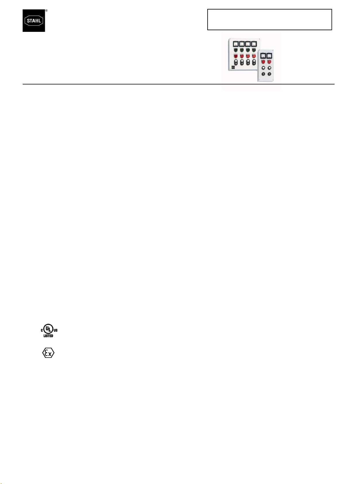
Series 8150/5
Explosion Protected Metallic Control Stations For
Hazardous and Corrosive Applications
Please read this entire document before beginning any work.
1. Safety Instructions
Installation and maintenance of these stainless
steel control stations should only be performed by
skilled and experienced personnel in accordance
with the National Electrical Code (NFPA 70) or the
Canadian Electrical Code (CEC) respectively and
any local regulations which relate to hazardous
(classified) locations.
CAUTION:
•Disconnect power supply before installing or
servicing these control stations.
•Cable or conduit entries may be field installed per
Section 3.4 & 3.5. of these instructions. All other
modifications can only be made after consulting
the manufacturer.
•Operate only undamaged and clean devices with
observations of the operating parameters in
Section 2.
•For a Class I Zone 1 conduit installation, conduit
seals are required, refer to NEC 505.16 (B) (1).
For any other cable or conduit installation NO
seals are required.
•Use only approved wiring methods for the loca-
tion, with the associate conduit/cable fittings.
Reference your local code.
•Supply wires shall be rated for 75˚C and internal
wires shall be rated 90˚C.
2. Technical Data
Please refer to the technical data on the enclosure
nameplate.
2.1 Certifications:
2.2 Environmental Protection:
IP 66 / Type 3, 4, 4X (depending on entry type)
2.3 Ambient Temperature:
(85˚C (185˚F) max.; -60˚C (-76˚F) min.
2.4
Component Data
2.4.1 Pilot Light, type 8010:
12V - 254V AC/DC, 0-60Hz
Terminal capacity 12-22 AWG. or 2.5 mm
2
tightened to 18 in-lbs. or 2 N-m
2.4.2 Contact Block, type 8082:
600V, 10A max.
Terminal capacity 12-22 AWG. or 2.5 mm
2
tightened to 18 in-lbs. or 2 N-m
2.4.3 Control Switch, type 8008/2-0...and 8008/2-1..:
600V, 10A max.
Terminal capacity 12-22 AWG. or 2.5 mm
2
tightened to 18 in-lbs. or 2 N-m.
2.4.4 Ammeter, type 8405:
600V. Ampere rating see data on device.
Terminal capacity 12-22 AWG. or 2.5 mm
2
tightened to 18 in-lbs. or 2 N-m.
3. Directions for Installation
3.1 Opening the enclosure
Fully loosen the cover screws using a screwdriver.
Do not remove these captive screws from the cover.
3.2 Enclosure Mounting
Mounting brackets are provided with the enclosure
which will accept up to 1/4" (6mm) screws.
3.3 Electrical Installation
There are two types of installation methods:
Conduit installation or cable installation. If the
enclosure is complete with factory installed entry
hardware, proceed to section 4.
If the enclosure does not include entry hardware,
select the appropriate hubs or cable connectors
from section 3.4 and install them as follows.
3.4 Installation of approved conduit hubs or cable
connectors
CAUTION: FIELD INSTALLED OPENINGS:
For field-installed openings, use a hand punch or
pneumatic type punch. Always wear safety glasses
and protective clothing when working.
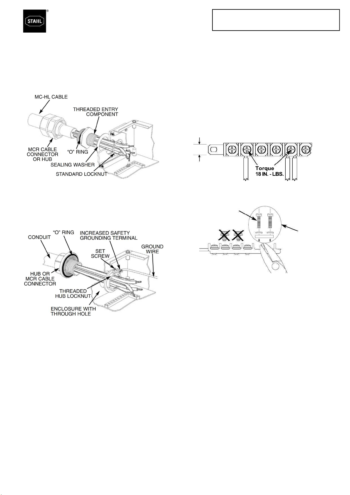
3.5 Conduit/Cable Installation
These enclosures make it necessary for the
metal cable connector and conduit hubs to be
bonded to the ground system. This can be accom-
plished by installing them either to method 1 or
method 2 as shown on next page.
Class I, Zone 1 & 2, AEx d e m [ia] IIC T6
Class I, Div. 2, Groups ABCD
Class I, Zone 1 & 2, Ex d e m [ia] IIC T6
Class I, Div. 2, per CEC J18-150
II 2 G Ex d e ia/ib [ia/ib] ma mb q IIA, IIB, IIC T6, T5, T4 Gb
2 D Ex tb IIIC IP66 T130°C, T95°C, T80°C Db
PTB 09 ATEX 1109
Ex d e ia/ib [ia/ib] ma mb q IIA, IIB, IIC T6, T5, T4 Gb
Ex tb IIIC IP66 T130°C, T95°C, T80°C Db
IECEx PTB 09.0049