2
EN
EN
EN
EN
EN
EN
EN
EN
EN
EN
EN
EN
EN
EN
EN
EN
EN
EN
EN
EN
EN
EN
EN
EN
EN
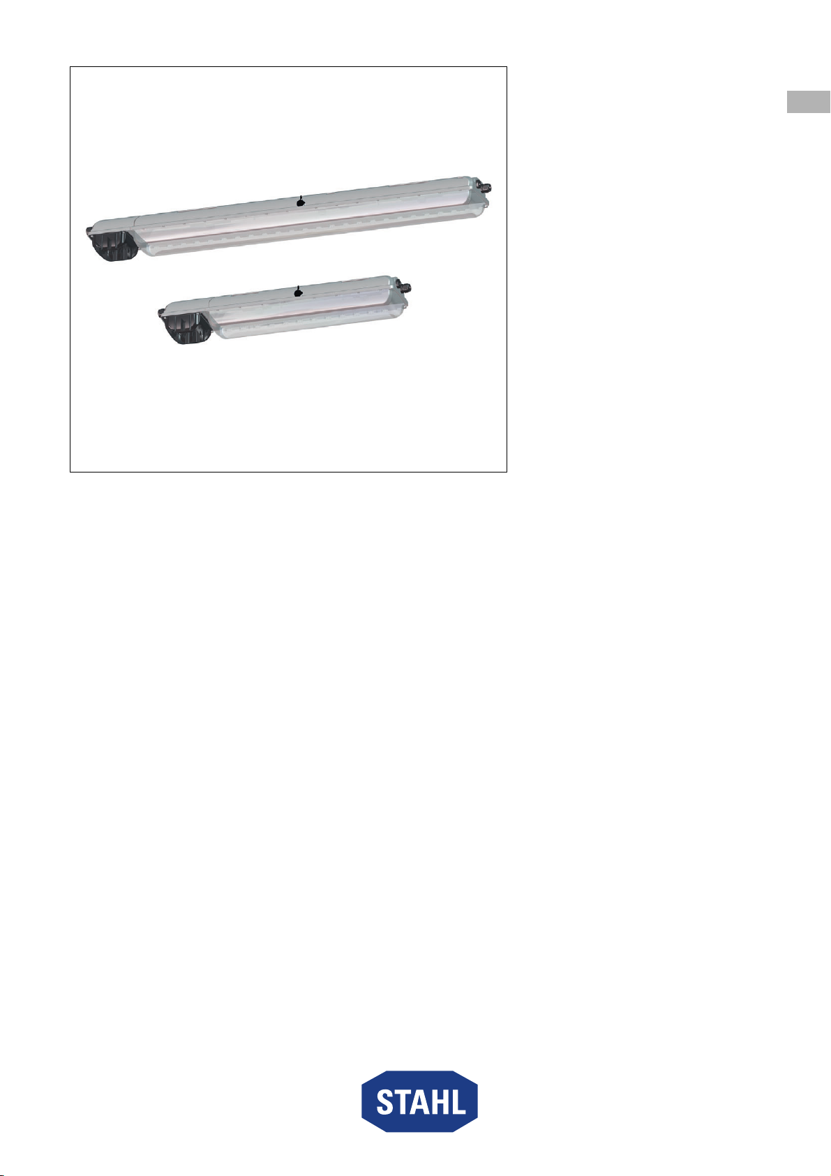
Emergency luminaire for fluorescent lamps
Series EXLUX 6409/5
Contents
1 General Information ............................................................................................3
1.1 Manufacturer .......................................................................................................3
1.2 Information regarding the operating instructions .................................................3
1.3 Further documents ..............................................................................................3
1.4 Conformity with standards and regulations .........................................................3
2 Explanation of the symbols .................................................................................4
2.1 Symbols in these operating instructions .............................................................4
2.2 Warning notes .....................................................................................................4
2.3 Symbols on the device ........................................................................................5
3 Safety notes ........................................................................................................5
3.1 Operating instructions storage ............................................................................5
3.2 Safe use ..............................................................................................................5
3.3 Intended Use .......................................................................................................6
3.4 Modifications and alterations ..............................................................................6
4 Function and device design ................................................................................6
4.1 Function ..............................................................................................................6
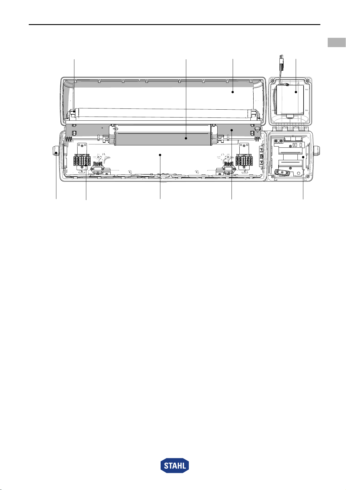
4.2 Device design .....................................................................................................7
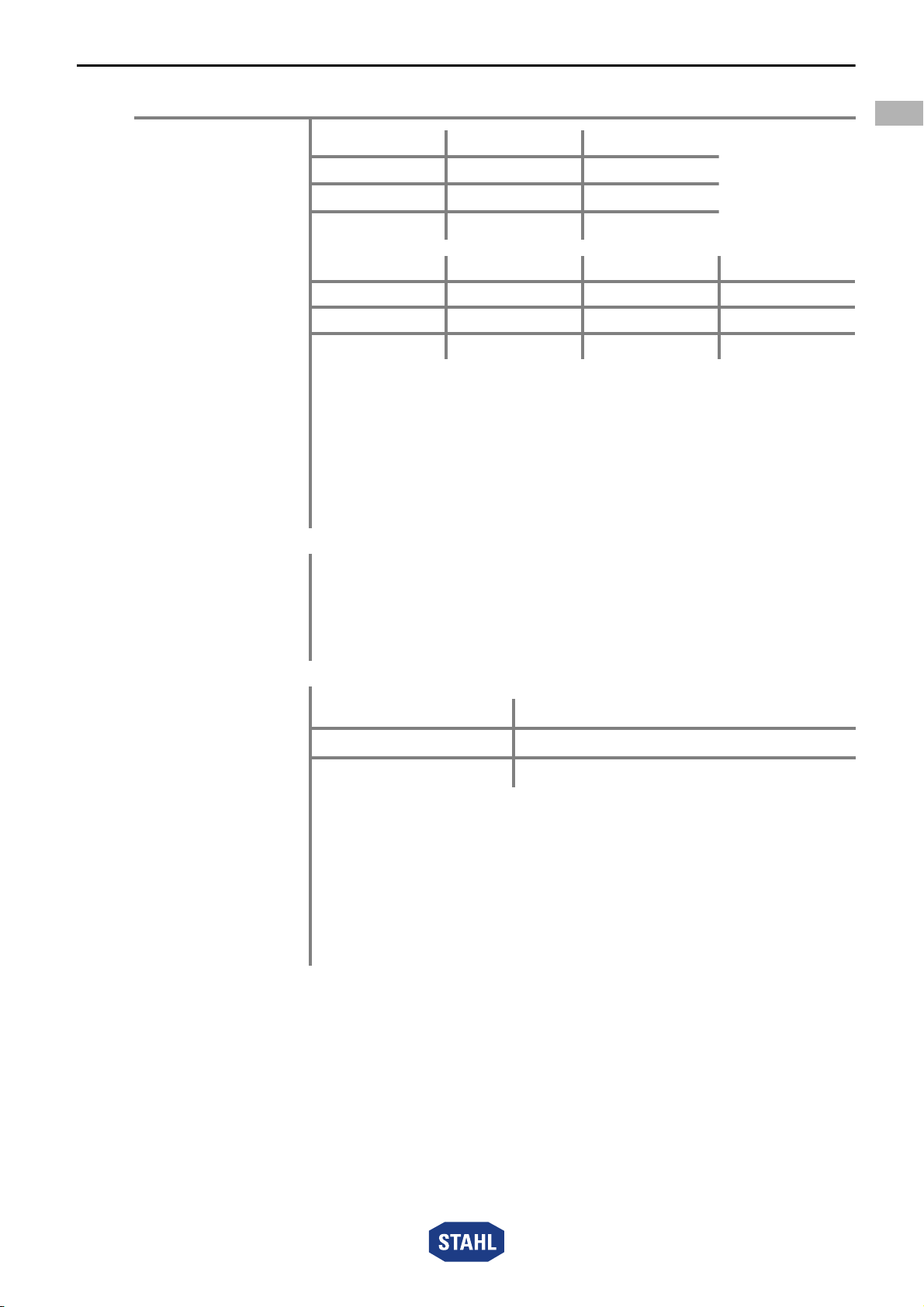
5 Technical data .....................................................................................................8
6 Engineering .......................................................................................................12
6.1 Mains operation ................................................................................................12
6.2 Emergency light blocking ..................................................................................13
7 Transport and storage .......................................................................................15
7.1 General .............................................................................................................15
7.2 Batteries ............................................................................................................15
8 Mounting and installation ..................................................................................15
8.1 Dimensions / fastening dimensions ..................................................................16
8.2 Removing protective foil ....................................................................................18
8.3 Mounting / dismounting, operating position ......................................................18
8.4 Installation .........................................................................................................22
9 Commissioning .................................................................................................27
10 Operation ..........................................................................................................28
10.1 Operating Modes ..............................................................................................28
10.2 Functional and rated operating time test ...........................................................29
10.3 Indications .........................................................................................................30
10.4 Troubleshooting ................................................................................................31
11 Maintenance, Overhaul, Repair ........................................................................32
11.1 Maintenance .....................................................................................................32
11.2 Repair ...............................................................................................................37
11.3 Returning the device .........................................................................................37
12 Cleaning ............................................................................................................38
13 Disposal ............................................................................................................38
14 Accessories and Spare parts ...........................................................................38