manuals.online logo
Brands
  1. Home
  2. •
  3. Brands
  4. •
  5. LOVATO ELECTRIC
  6. •
  7. Relay
  8. •
  9. LOVATO ELECTRIC PMA30 User manual

LOVATO ELECTRIC PMA30 User manual

I233 I GB F E 04 14 31100101
LOVATO ELECTRIC S.P.A.
24020 GORLE (BERGAMO) ITALIA
VIA DON E. MAZZA, 12
TEL. 035 4282111
TELEFAX (Nazionale): 035 4282200
TELEFAX (International): +39 035 4282400
E-mail info@LovatoElectric.com
Web www.LovatoElectric.com
1
PMA30
I
RELÈ AMPEROMETRICO DI MINIMA O MASSIMA CORRENTE AC/DC
GB
MINIMUM OR MAXIMUM AC/DC CURRENT RELAY
F
RELAIS DE MESURE ET DE CONTROLE DU COURANT MINIMUM OU
MAXIMUM AC/DC
E
RELÉ AMPERIMÉTRICO DE MÍNIMA O MÁXIMA CORRIENTE AC/DC
ATTENZIONE!
–
Leggere attentamente il manuale prima
dell’utilizzo e l’installazione.
–
Questi apparecchi devono essere installati
da personale qualificato, nel rispetto delle
vigenti normative impiantistiche, allo
scopo di evitare danni a persone o cose.
–
Il costruttore non si assume responsabilità
in merito alla sicurezza elettrica in caso di
utilizzo improprio del dispositivo.
–
I prodotti descritti in questo documento
sono suscettibili in qualsiasi momento di
evoluzioni o modifiche. Le descrizioni ed i
dati a catalogo non possono pertanto
avere alcun valore contrattuale.
–
Un interruttore magnetotermico va
compreso nell’impianto elettrico
dell’edificio. Esso deve trovarsi in stretta
vicinanza dell’apparecchio ed essere
facilmente raggiungibile da parte
dell’operatore.
Deve essere marchiato come il dispositivo
di interruzione dell’apparecchio:
IEC/EN 61010-1 § 6.11.2.
–
Installare lo strumento in contenitore e/o
quadro elettrico con grado di protezione
minimo IP40
.
–
Pulire lo strumento con panno morbido,
non usare prodotti abrasivi, detergenti
liquidi o solventi.
DESCRIZIONE
Il PMA30 è un relé amperometrico per
corrente alternata o continua unidirezionale,
con funzioni d’intervento di minima o di
massima corrente. L’alimentazione ausiliaria
è ad ampio range 24...240VAC/DC.
L’ingresso di corrente può essere connesso
mediante TA o direttamente sul circuito da
controllare sino ad una tensione massima di
415VAC.
CARATTERISTICHE
–
Relè amperometrico di minima o
massima corrente.
–
Alimentazione 24...240VAC/DC.
–
Misure TRMS in AC/DC.
–
Inserzione mediante TA esterno o diretta.
–
Ripristino automatico o manuale.
–
Fondoscala 5A o 16A configurabile.
–
Uscita a relè con contatto in scambio
configurabile NA o NC.
–
Ingresso di ripristino o inibizione
configurabile.
–
Soglia di minima o massima corrente
regolabile 5...100%.
–
Isteresi regolabile 1...50%.
–
Tempo inibizione 1...60s.
–
Ritardo intervento 0,1...30s.
– 1
LED verde di segnalazione
alimentazione e durata inibizione.
– 1
LED rosso di segnalazione intervento.
WARNING!
–
Carefully read the manual before the
installation or use.
–
This equipment must be installed by
qualified personnel, complying to current
standards, to avoid damages or safety
hazards. Products illustrated herein are
subject to alteration and changes without
prior notice.
–
The manufacturer cannot be held
responsible for electrical safety in case of
improper use of the equipment.
–
Technical data and descriptions in the
publication are accurate, to the best of
our knowledge, but no liabilities for
errors, omissions or contingencies
arising therefrom are accepted.
–
A circuit breaker must be included in the
electrical installation of the building.
It must be installed close by the
equipment and within easy reach of the
operator.
It must be marked as the disconnecting
device of the equipment:
IEC/EN 61010-1 § 6.11.2.
–
Fit the device in an enclosure or cabinet
with minimum IP40 degree protection.
–
Clean the equipment with a soft cloth and
do not use abrasive products, liquid
detergents or solvents.
DESCRIPTION
The PMA30 is a control relay for alternating
or unidirectional direct current monitoring,
with minimum or maximum current tripping
functions. Wide range auxiliary supply
voltage is 24...240VAC/DC.
The current input can be connected directly
or by CT to the circuit to control up to a
maximum voltage of 415VAC.
CHARACTERISTICS
–
Protection relay for minimum or
maximum current
–
Supply 24...240VAC/DC
–
TRMS AC/DC measurements
–
Connection either directly or by external
CT
–
Automatic or manual reset
–
Configurable end-scale value: 5A or 16A
–
Output relay with changeover contact
configurable as NO or NC
–
Configurable input as reset or inhibition
–
Minimum or maximum current threshold
adjustment: 5...100%
–
Adjustable hysteresis: 1...50%
–
Inhibition time: 1...60s
–
Tripping delay: 0.1...30s
– 1
Green LED indicator for power supply
and inhibition time
– 1
Red LED indicator for current tripping.
¡ATENCIÓN!
–
Leer detenidamente el manual antes del
uso y la instalación.
– Estos aparatos deben ser instalados por
personal cualificado y de conformidad con
las normativas vigentes en materia de
instalaciones a fin de evitar daños
personales o materiales.
–
El fabricante queda eximido de toda
responsabilidad en materia de seguridad
eléctrica en caso de uso impropio del
dispositivo.
–
Los productos descritos en este documento
pueden ser modificados o perfeccionados
en cualquier momento. Por tanto, las
descripciones y los datos aquí indicados
no implican algún vínculo contractual.
–
La instalación eléctrica del edificio debe
contar con un interruptor magnetotérmico.
Éste debe estar colocado muy cerca del
aparato, en una ubicación de fácil acceso
para el operador. Debe estar marcado
como dispositivo de interrupción del
aparato: IEC/EN 61010-1 § 6.11.2.
–
Instalar el instrumento en una caja y/o
cuadro eléctrico con grado de protección
mínimo IP40.
– Limpiar el instrumento con un paño suave,
evitando el uso de productos abrasivos,
detergentes liquidos o disolventes.
DESCRIPCIÓN
PMA30 es un relé amperimétrico para
corriente alterna o continua unidireccional,
con funciones de intervención de mínima y
de máxima corriente. La tensión auxiliar de
alimentación es muy amplia
(24...240VAC/DC). La entrada de corriente
puede conectarse mediante TC o
directamente en el circuito a controlar, hasta
una tensión máxima de 415VAC.
CARACTERÍSTICAS
–
Relé amperimétrico de mínima y máxima
corriente.
–
Alimentación 24...240VAC/DC.
–
Mediciones TRMS en AC/DC.
–
Conexión mediante TC externo o directa.
–
Rearme automático o manual.
–
Calibre 5A ó 16A configurable.
–
Salida de relé con contacto conmutado,
configurable NA o NC.
–
Entrada de rearme o inhibición
configurable.
–
Umbral de mínima y máxima corriente
ajustable 5...100%.
–
Histéresis ajustable 1...50%.
–
Tiempo inhibición 1...60s.
–
Retardo intervención 0,1...30s.
– 1
LED verde de señal alimentación y
duración inhibición.
– 1
LED rojo de señal intervención.
ATTENTION !
–
Lire attentivement le manuel avant
l’installation ou toute utilisation.
–
Ces appareils doivent être installés par un
personnel qualifié en respectant les
normes en vigueur relatives aux
installations pour éviter tout risque pour
le personnel et le matériel.
– Le fabricant ne peut être tenu responsable
dela súreté électrique en cas de mauvaise
utilisation de l’équipement.
–
Les produits décrits dans ce document
peuvent à tout moment être susceptibles
d’évolutions ou de modifications. Les
descriptions et les données y figurant ne
peuvent en conséquence revêtir aucune
valeur contractuelle.
–
Dans l’installation électrique de l’édifice,
il faut prévoir un disjoncteur
magnétothermique, situé à proximité de
l’appareil et d’accès facile, portant la
même marque que le dispositif
d’interruption de l’appareil :
IEC/EN 61010-1 § 6.11.2.
–
L’instrument doit être installé dans un
coffret et/ou un tableau électrique ayant
un degré de protection minimum IP40.
– Nettoyer l’equipement
avec un tissu propre
et ne pas employer les produits abrasifs, les
détergents liquides ou les dissolvants.
DESCRIPTION
Le PMA30 est un relais de courant alterné ou
continu unidirectionnel, avec des fonctions
de déclenchement en cas de valeurs de
courant minimum ou maximum.
L’alimentation auxiliaire offre une large
gamme 24 à 240VAC/DC. L’entrée de
courant peut être branchée à travers TI ou
directement sur le circuit à contrôler jusqu’à
une tension maximum de 415VAC.
CARACTERISTIQUES
–
Relais de mesure et de contrôle du
courant minimum ou maximum
–
Alimentation 24 à 240VAC/DC
–
Mesures en valeur efficace vraie en AC/DC
–
Connexion directe ou par TI externe
–
Réarmement automatique ou manuel
–
Pleine échelle 5A ou 16A configurable
–
Relais de sortie avec contact inverseur
configurable O ou F
–
Entrée de réarmement ou d’inhibition
configurable
–
Seuil de courant minimum ou maximum
réglable : 5 à 100%
–
Hystérésis régable : 1 à 50%
–
Temps d’inhibition 1 à 60s
–
Retard de déclenchement 0,1 à 30s
– 1
DEL verte signalant l’alimentation et la
durée d’inhibition
– 1
DEL rouge signalant le déclenchement.
I233 I GB F E 04 14 31100101
2
SCELTA DEL MODO DI FUNZIONAMENTO
ATTENZIONE!
Si consiglia di effettuare la scelta del modo
di funzionamento con apparecchio
disalimentato allo scopo di evitare situazioni
pericolose nel momento del cambio
funzione. E’ comunque possibile effettuare il
cambio con apparecchio alimentato.
Lo spostamento del selettore con
apparecchio alimentato provoca il lampeggio
contemporaneo di tutti i LED per 5s ed il
ripristino dell’apparecchio, con successivo
riavvio nella nuova modalità operativa.
Impostare tramite l’apposito selettore 5] il
modo di funzionamento richiesto:
OPERATING MODE CHOICE
ATTENTION!
It is recommended to make the operating
mode choice when the device is switched off
to avoid dangerous conditions during
function change.
It is however possible to make the change
with a powered device. The rotary switch
adjustment causes the simultaneous flashing
of all the LEDs for 5s, the device reset and
subsequent power up with the new operating
mode.
Regulate the relative rotary switch 5] to the
required operating mode:
SELECCIÓN DEL MODO DE FUNCIONAMIENTO
¡ATENCIÓN!
Se recomienda efectuar la selección del modo
de funcionamiento con el aparato
desconectado de la red, a fin de evitar
situaciones peligrosas al momento de cambiar
la función. De todos modos, es posible
efectuar el cambio con el aparato conectado a
la red. El desplazamiento del selector con el
aparato bajo tensión provoca el encendido
intermitente y simultáneo de todos los LED
por 5s y el rearme del aparato, con el
encendido posterior en el nuevo modo
operativo.
Seleccionar el modo de funcionamiento que
se desea sirviéndose del selector 5]:
CHOIX DU MODE DE FONCTIONNEMENT
ATTENTION!
Il est réccomandé d’éteindre l’appareil pour
choisir le mode de fonctionnement afin
d’éviter des situations dangereuses.
Il est possible toutefois changer le mode
quand l’appareil est sous tension ; dans ce
cas, toutes les DEL clignoteront pendant 5s
et l’appareil sera éteint puis rallumé en
chargeant le mode de fonctionnement choisi.
Utilisez le selecteur approprié 5] pour
changer le mode de fonctionnement :
MODE Funzioni Relay Latch
A Minima corrente OFF OFF
B ON
C ON OFF
D ON
E Massima corrente OFF OFF
F ON
G ON OFF
H ON
Function
Minimum current
Maximum current
Funciones
Mínima corriente
Máxima corriente
Fonctions
Courant minimum
Courant maximum
RELAY OFF (Relè diseccitato)
Relè normalmente diseccitato.
RELAY ON (Relè eccitato)
Relè normalmente eccitato.
LATCH OFF (Senza memoria d’intervento)
L’ingresso Y se alimentato inibisce il
funzionamento dell’apparecchio, se
disalimentato abilita il funzionamento
dell’apparecchio ma solo dopo il tempo di
inibizione impostato. Con questa modalità il
ripristino avviene automaticamente quando il
valore di corrente scende al di sotto del
valore di isteresi (potenziometro 3]) rispetto
al valore di corrente impostato (Es. valore
intervento di massima 50%=8A, isteresi
20%, valore di ripristino 40%=6,4A).
Nel caso di utilizzo come minima corrente il
ripristino avviene quando la corrente sale al
di sopra del valore di isteresi (potenziometro
3]) rispetto al valore di corrente impostato
(Es. valore intervento di minima 50%=8A,
isteresi 20%, valore di ripristino 60%=9,6A).
LATCH ON (Con memoria d’intervento)
E’ possibile mantenere in memoria
l’intervento con l’ingresso Y disalimentato
oppure resettare l’apparecchio dopo un
intervento con l’ingresso Y alimentato. Il
ripristino è possibile solo se la corrente è
rientrata nei limiti impostati. In questa
modalità il ripristino avviene senza il tempo
di inibizione.
Il ripristino può essere effettuato anche
disalimentando l’apparecchio.
Mantenere Y chiuso, l’apparecchio ripristina
automaticamente e senza il tempo di
inibizione.
COLLEGAMENTO
La corrente viene rilevata sui morsetti B1 e
C(-). L’ingresso può essere connesso
mediante TA (AC) esterno oppure in
RELAY OFF
Output relay normally de-energised.
RELAY ON
Output relay normally energised.
LATCH OFF (With no tripping memory)
If powered, input Y inhibits the unit
operation. If not powered, the unit operation
is enabled only after the programmed
inhibition time lapses. In this mode, resetting
takes place automatically when the current
value descreases below the hysteresis value
set by potentiometer 3] with respect to the
set current value (E.g. Tripping value of
maximum at 50%=8A, 20% hysteresis, 40%
reset value=6.4A).
In the case of minimum current, resetting
takes place when the current increases
above the hysteresis value set by
potentiometer 3] with respect to the set
current value (E.g. Tripping value of
minimum at 50%=8A, 20% hysteresis, 60%
reset value=9.6A).
LATCH ON (With tripping memory)
The tripping latch is maintained when input Y
is not powered or the unit is reset after
tripping when input Y is powered. Resetting
can be obtained only if the current has
returned within set limits. In this mode, the
reset takes place without the inhibition time.
Resetting also occurs by removing power
from the relay.
If maintained closed, the unit automatically
resets without the inhibition time.
CONNECTION
The current signal is obtained on terminals
B1 and C (-). The current input can be made
by means of external CT (AC only) or
RELAY OFF (Relé desexcitado)
Relé normalmente desexcitado.
RELAY ON (Relé excitado)
Relé normalmente excitado.
LATCH OFF (Sin memoria de intervención)
La entrada Y alimentada inhibe el
funcionamiento del aparato, mientras que
desalimentada habilita el funcionamiento del
aparato pero tras el tiempo de inhibición
configurado. Con este modo de
funcionamiento, el
rearme
se realiza
automáticamente cuando el valor de corriente
desciende por debajo del valor de histéresis
(potenciómetro 3]) respecto del valor de
corriente configurado (ej. valor intervención
de máxima 50%=8A, histéresis 20%, valor de
restablecimiento 40%=6,4A).
Si se utiliza para la corriente mínima, el
rearme
se realiza cuando el valor de corriente
supera el valor de histéresis (potenciómetro
3]) respecto del valor de corriente
configurado (ej. valor intervención de mínima
50%=8A, histéresis 20%, valor de
restablecimiento 60%=9,6A).
LATCH ON (Con memoria de intervención)
Es posible mantener memorizada la
intervención con la entrada Y desalimentada o
rearme el aparato tras una intervención
con la
entradaYalimentada. El
rearme sólo es posible
si la corriente ha vuelto a estar dentro de los
límites configurados. Con este modo de
funcionamiento, el rearme se realiza sin el
tiempo de inhibición. El rearme también puede
realizarse interrumpiendo la alimentación del
aparato.
Si se mantiene cerrado, el aparato se
restablece automáticamente y sin el tiempo
de inhibición.
CONEXIÓN
La corriente se mide en los bornes B1 y C (-).
La entrada puede conectarse mediante TC
externo (AC) o en forma directa (AC/DC).
RELAY OFF (relais désexcité)
Relais normalement désexcité.
RELAY ON (relais excité)
Relais normalement excité.
LATCH OFF (Sans mémoire de déclenchement)
Si l’entrée Y est alimentée, elle interdit le
fonctionnement de l’appareil ; si elle est
désactivée, elle active le fonctionnement de
l’appareil mais seulement après le temps
d’inhibition programmé. Dans ce mode, le
réarmement se produit automatiquement
quand la valeur de courant descend au-
dessous de la valeur d’hystérésis
(potentiomètre 3]) par rapport à la valeur de
courant définie (ex. : valeur de déclenchement
maximale 50%=8A, hystérésis 20%, valeur
de réarmement 40%=6,4A).
Pour le courant minimum, le réarmement se
produit quand le courant dépasse la valeur
d’hystérésis (potentiomètre 3]) par rapport à
la valeur de courant définie (ex. : valeur de
déclenchement minimale 50%=8A, hystérésis
20%, valeur de réarmement 60%=9,6A).
LATCH ON (Avec mémoire de déclenchement)
On peut mémoriser le déclenchement si
l’entrée Y est désactivée ou réarmer l’appareil
après un déclenchement si l’entrée Y est
alimentée. Le réarmement n’est possible que
si le courant respecte les limites
programmées. Dans ce mode, le réarmement
se produit sans le temps d’inhibition.
Le réarmement se produit aussi si l’on coupe
l’alimentation de l’appareil.
Si on le maintient fermé, l’appareil se réarme
automatiquement sans le temps d’inhibition.
CONNEXION
Le courant est relevé sur les bornes B1 et
C(-). L’entrée peut être branchée par TI (AC)
externe ou connexion directe (AC/DC).
5A 16A
®
2
4
6
1
3
5
ATTENTION !
Appareil à réarmement
automatique.
I233 I GB F E 04 14 31100101
3
inserzione diretta (AC/DC).
In questo caso la tensione sui morsetti non
deve essere superiore a 415VAC/DC e, in
caso di misura in DC, deve essere rispettata
la polarità di collegamento.
L’alimentazione ausiliaria dell’apparecchio
avviene tramite i morsetti A1 e A2.
L’ingresso Y può svolgere la funzione di
ripristino o inibizione in base al modo di
funzionamento scelto nella tabella.
NORMALE FUNZIONAMENTO
All’alimentazione il PMA30 effettua il tempo
di inibizione impostabile mediante il
potenziometro 4] durante il quale il LED
verde lampeggia. Dopo il tempo di inibizione
e in condizioni di normale funzionamento
riferite al valore impostato dal potenziometro
1], il LED verde “ON” è acceso fisso, il LED
rosso è spento ed il relè di uscita è nelle
condizioni di normale funzionamento
(funzionamento normalmente eccitato o
diseccitato in base alla funzione scelta in
tabella).
Quando la corrente supera o scende al di
sotto del valore impostato, il LED rosso
lampeggia ed al termine del relativo tempo di
ritardo impostato tramite il potenziometro
2], il relè cambia stato ed il LED rosso resta
acceso fisso.
La modalità di ripristino dipende dalla
funzione di memoria “Latch” scelta.
connected directly (AC/DC).
In this case, voltage at terminals must not be
greater than 415VAC/DC and polarity must
be respected should DC measurement be
used.
The auxiliary supply of the device is
connected by A1 and A2 terminals.
Input Y can carry out the reset or inhibition
function based on the operating mode
selected per the table.
NORMAL OPERATION
At power on, the PMA30 conducts the
inhibition time set by potentiometer 4]
during which the green LED flashes. At
lapsing and with normal operating conditions
referred to the value set by potentiometer
1], the green “ON” LED is switched on
constantly, the red LED is off and the output
relay is in normal operating conditions
(normally energised or de-energised based
on the function selected per the table).
When the current value increases above or
decreases below the set value, the red LED
flashes. At the delay time lapsing set by
potentiometer 2], the relay changes state
and the red LED remains constantly on.
Resetting mode depends on the “Latch”
function selected.
En este caso, la tensión en los bornes no
tiene que superar los 415VAC/DC y, en caso
de medición en DC, debe respetarse la
polaridad de conexión.
La tensión auxiliar de alimentación del
aparato llega mediante los bornes A1 y A2.
La entrada Y puede cumplir la función de
rearme o inhibición, según el modo de
funcionamiento seleccionado en la tabla.
FUNCIONAMIENTO NORMAL
Al conectarse la alimentación, el PMA30 da
inicio al tiempo de inhibición establecido
mediante el potenciómetro 4], durante el
cual destella el LED verde. Tras el tiempo de
inhibición y en condicion de normal
funcionamiento respecto del valor
establecido por el potenciómetro 1], el LED
verde “ON” se enciende en forma estable, el
LED rojo se apaga y el relé de salida queda
en condición de normal funcionamiento
(normalmente excitado o desexcitado en
base a la función seleccionada en la tabla).
Cuando la corriente supera o desciende por
debajo del valor configurado, el LED rojo
destella y, al término del tiempo de retardo
establecido mediante el potenciómetro 2], el
relé cambia de estado y el LED rojo queda
encendido de forma estable.
El modo de rearme depende de la función de
memoria “Latch” seleccionada.
Dans ce cas, la tension sur les bornes ne
doit pas dépasser 415VAC/DC et, en cas de
mesure en DC, elle doit respecter la polarité
de connexion.
L’alimentation auxiliaire de l’appareil doit être
reliée aux bornes A1 et A2.
L’entrée Y peut avoir la fonction de
réarmement ou inhibition selon le mode de
fonctionnement choisi dans le tableau.
FONCTIONNEMENT NORMAL
Lors de la mise sous tension, le PMA30
applique le temps d’inhibition défini à travers
le potentiomètre 4] et fait clignoter la DEL
verte. Le délai d’inhibition étant échu et en
conditions de fonctionnement normal par
rapport à la valeur définie avec le
potentiomètre 1], la DEL verte “ON” reste
allumée fixe, la DEL rouge s’éteint et le relais
de sortie reste en condition de
fonctionnement normal (normalement excité
ou désexcité selon la fonction choisie dans le
tableau).
Quand le courant dépasse ou descend au-
dessous de la valeur définie, la DEL rouge
clignote. Au terme du délai de retard défini à
travers le potentiomètre 2], le relais change
d’état et la DEL rouge reste allumée fixe.
Le réarmement se produit selon la modalité
“Latch” définie.
WIRING DIAGRAM SCHEMI DI COLLEGAMENTO ESQUEMA DE CONEXIÓNSCHEMA DE CONNEXION
ATTENZIONE!
Apparecchio con rispristino
automatico.
CAUTION!
Device with automatic resetting.
¡ATENCIÓN!
Aparato con rearme automático.
L2
L3
L1
A
O
D
L
 
16A
A1 A2
METER
14 12 11
Y
C
Inhibition or
Reset
B1
C(-)


L2
L3
L1
A
O
D
L
  
16A
A1 A2
METER
14 12 11
Y
C
Inhibition or
Reset
B1
C(-)

Schema di collegamento trifase
con inserzione mediante TA.
Wiring diagram for three phase
with CT connection.
Schéma pour connexion
triphasée par TI.
Esquema de conexión con
activación mediante TC.
Schema di collegamento trifase
con inserzione diretta.
Wiring diagram for three phase
with direct connection.
Schéma pour connexion
triphasée directe.
Esquema de conexión con
activación directa.
N
LA
O
D
L
16A
A1 A2
METER
14 12 11
Y
C
Inhibition or
Reset
B1
C(-)
  

Schema di collegamento trifase
con inserzione mediante TA.
Wiring diagram for three phase with
CT connection.
Schéma pour connexion triphasée
par TI.
Esquema de conexión con activación
mediante TC.
N(-)
L(+) A
O
D
L

16A
A1 A2
METER
14 12 11
Y
C
Inhibition or
Reset
B1
C(-)
 

Schema di collegamento monofase
con inserzione diretta.
Wiring diagram for single-phase
with direct connection.
Schéma pour connexion
monophasée directe.
Esquema de conexión con activación
directa.
   
5A16A
®
Y121411
A1 A2 B1 C(-)
DIMENSIONS mm]DIMENSIONI mm] DIMENSIONES mm]DIMENSIONS mm]
35.8
104.7
58.1
59.9
45
99
Ø4.2
5 43.8
90
I233 I GB F E 04 14 31100101
4
Relay OFF
Threshold Max current
Hysteresis Max current
Relay ON
Inhibition time
11
12
14
12
14
11
t > trip delay
R
Trip Max current
ON
A
B
CDEF
G
H
A
B
CDEF
G
H
A2
A1
Y
A1
Inhibition C
Inhibition Inhibition Inhibition
Positions
t < trip delay
t < trip delay t
   

Funzionamento di massima
corrente senza memoria
d’intervento (Latch OFF).
Maximum current operation with
no tripping memory (Latch OFF).
Fonctionnement en courant
maximum sans la mémoire de
déclenchement (Latch OFF).
Funcionamiento de máxima
corriente sin memoria de
intervención (Latch OFF).
t > trip delayt > trip delay
t
Relay OFF
Relay ON
Inhibition time
11
12
14
12
14
11
Hysteresis Min current
Threshold Min current
ON
Trip Min current
t < trip delay
A
B
CDEF
G
H
A
B
CDEF
G
H
A2
A1
Y
A1
Reset C
Inhibition Inhibition Inhibition
Positions
   

Funzionamento di minima corrente
con memoria d’intervento
(Latch ON).
Minimum current operation with
tripping memory (Latch ON).
Fonctionnement en courant
minimum avec la mémoire de
déclenchement (Latch ON).
Funcionamiento de mínima
corriente con memoria de
intervención (Latch ON).
t > trip delay
11
Relay OFF
12
Threshold Min current
Hysteresis Min current
Relay ON
12
14
11
14
Inhibition time
t < trip delay
ON
Trip Min current
A
B
CDEF
G
H
A
B
CDEF
G
H
A2
A1
Y
A1
Inhibition C
Inhibition Inhibition Inhibition
Positions
t < trip delay
1
   

Funzionamento di minima corrente
senza memoria d’intervento
(Latch OFF).
Minimum current operation with
no tripping memory (Latch OFF).
Fonctionnement en courant
minimum sans la mémoire de
déclenchement (Latch OFF).
Funcionamiento de mínima
corriente sin memoria de
intervención (Latch OFF).
OPERATIONAL DIAGRAM DIAGRAMMI DI FUNZIONAMENTO DIAGRAMA DE FUNCIONAMIENTODIAGRAMME DE FONCTIONNEMENT
t > trip delay
Inhibition time
Hysteresis Max current
Threshold Max current
Relay OFF 11
14
12
12
14
11
Relay ON
t > trip delay t < trip delay
R
ON
Trip Max current
T
A
B
CDEF
G
H
A
B
CDEF
G
H
A2
A1
Y
A1
Reset C
Inhibition Inhibition Inhibition
Positions
   

Funzionamento di massima
corrente con memoria
d’intervento (Latch ON).
Maximum current operation with
tripping memory (Latch ON).
Fonctionnement en courant
maximum avec la mémoire de
déclenchement (Latch ON).
Funcionamiento de máxima
corriente con memoria de
intervención (Latch ON).
I233 I GB F E 04 14 31100101
5
CARATTERISTICHE TECNICHE
Circuito i alimentazione
Tensione nominale Us 24-240V
Frequenza nominale 50/60Hz ±5%
Limiti di funzionamento 0,85...1,1Us
Potenza massima assorbita 3,2VA
Potenza massima dissipata 1,6W
Immunità alla microinterruzione ≤ 40ms
Ingresso amperometrico
Tipo di inserzione Mediante TA o diretta
Tensione massima 415V
Corrente nominale Ie 16A
Limiti di misura 0,25...16A
Tipo di ingresso Shunt
Tipo di misura AC/DC TRMS
Limite termico permanente 16A
Limite termico di breve durata 5In per 1s
Limite dinamico 160A per 10ms
Autoconsumo 0,7VA
Ingresso Y
Tensione nominale Uc 24-240V
Limiti di funzionamento 0,85...1,1Uc
Potenza assorbita/dissipata 1,8VA/0,1W
Durata minima comando ≥ 100ms
Impostazioni
Scelta fondoscala di misura Ie 5A o 16A
Intervento di minima o massima corrente 5...100 %Ie]
Isteresi rispetto al valore impostato 1...50%
Ritardo intervento 0,1...30s
Tempo di inibizione 1...60s
Errori
Impostazione ±9%
Relè i uscita
Numero di uscite 1
Tipo di uscita 1 contatto in scambio
Tensione nominale di lavoro 250V~
Tensione massima d’interruzione 400V~
Designazione secondo IEC/EN 60947-5-1 AC1 8A-250V~/ B300
Durata elettrica 105operazioni
Durata meccanica 30x106operazioni
Isolamento
Tensione nominale di tenuta a impulso Uimp 4kV
Tensione di tenuta a frequenza d’esercizio 2,5kV
Tensione nominale d’isolamento Ui 415V~
Con izioni ambientali
Temperatura d’impiego -20...+60°C
Temperatura di stoccaggio -30...+80°C
Umidità relativa <90%
Grado di inquinamento massimo 3
Categoria d’installazione 3
Categoria di misura III
Connessioni
Tipo di terminali Fissi
Sezione conduttori 0,2...4,0 mm2(24...12 AWG)
Coppia di serraggio 0,8Nm (7lbin)
Contenitore
Esecuzione 2 moduli (DIN 43880)
Materiale Poliammide
Montaggio Guida 35mm (IEC/EN 60715)
oppure a vite a mezzo clip estraibili
Grado di protezione IP40 sul fronte - IP20 sui morsetti
Peso 121g
Omologazioni e conformità
Omologazioni ottenute cULus, GOST
UL Marking Use 60°/75° CU wire only.
AWG 12-18 Stranded-solid. Torque 7-9lbin.
Conformi alle norme IEC/EN 60255-5, IEC/EN 61010-1,
IEC/EN 61000-6-2, IEC/EN 61000-6-3,
IEC/EN 60068-2-6, IEC/EN 60068-2-27,
IEC/EN 60028-2-61, UL 508, CSA C22.2 N° 14.
I GB TECHNICAL CHACTERISTICS
Power supply circuit
Rated operating voltage Us 24-240V
Rated frequency 50/60Hz ±5%
Operating range 0.85...1.1Us
Maximum power consumption 3.2VA
Maximum power dissipation 1.6W
Micro-breaking immunity ≤ 40ms
Current input
Type of connection By CT or direct
Maximum voltage 415V
Rated current Ie 16A
Measuring range 0.25...16A
Type of input Shunt
Measuring method AC/DC TRMS
Overload capacity 16A
Overload peak 5In for 1s
Dynamic limit 160A for 10ms
Burden 0.7VA
Input Y
Rated voltage Uc 24-240V
Operating range 0.85...1.1Uc
Power consumption/dissipation 1.8VA/0.1W
Minimum control time ≥ 100ms
A justments
Full scale measurement choice Ie 5A or 16A
Tripping for minimum or maximum current 5...100 %Ie]
Hysteresis respect to adjusted value 1...50%
Tripping delay 0.1...30s
Inhibition time 1...60s
Errors
Programming ±9%
Relay outputs
Number of outputs 1
Type of output 1 changeover contact
Rated operating voltage 250V~
Maximum switching voltage 400V~
IEC/EN 60947-5-1 designation AC1 8A-250V~/ B300
Electrical life 105ops
Mechanical life 30x106ops
Insulation
Rated impulse withstand voltage Uimp 4kV
Power frequency withstand voltage 2.5kV
Rated insulation voltage Ui 415V~
Ambient con itions
Operating temperature -20...+60°C
Storage temperature -30...+80°C
Relative humidity <90%
Maximum pollution degree 3
Installation category 3
Mesure category III
Connections
Type of terminals Fixed
Conductor cross section 0.2...4.0 mm2(24...12 AWG)
Tightening torque 0.8Nm (7lbin)
Housing
Version 2 modules (DIN 43880)
Material Polyamide
Mounting On 35mm DIN rail (IEC/EN 60715)
or by screws using extractible clips
Degree of protection IP40 on front - IP20 at terminals
Weight 121g
Certifications an compliance
Certifications obtained cULus, GOST
UL Marking Use 60°/75° CU wire only.
AWG 12-18 Stranded-solid. Torque 7-9lbin.
Reference standards IEC/EN 60255-5, IEC/EN 61010-1,
IEC/EN 61000-6-2, IEC/EN 61000-6-3,
IEC/EN 60068-2-6, IEC/EN 60068-2-27,
IEC/EN 60028-2-61, UL 508, CSA C22.2 N° 14.
I233 I GB F E 04 14 31100101
6
CARACTERISTIQUES TECHNIQUES
Circuit ’alimentation
Tension assignée Us 24-240V
Fréquence assignée 50/60Hz ±5%
Limites de fonctionnement 0,85...1,1Us
Consommation maxi 3,2VA
Dissipation maxi 1,6W
Immunité aux micro-interruptions ≤ 40ms
Entrée e courant
Type de connexion Par TI ou directe
Tension maxi 415V
Courant assigné Ie 16A
Limite de mesure 0,25...16A
Type d’entrée Shunt
Méthode de mesure AC/DC TRMS
Surintensité admissible 16A
Pic de courant admissible 5In pendant 1s
Limite dynamique 160A pendant 10ms
Autoconsommation 0,7VA
Entrée Y
Tension assignée Uc 24-240V
Limites de fonctionnement 0,85...1,1Uc
Consommation/dissipation 1,8VA/0,1W
Temps de contrôle mini ≥ 100ms
Réglages
Choix pleine échelle de mesure Ie 5A ou 16A
Déclenchement pour courant mini ou maxi 5...100 %Ie]
Hystérésis par rapport à la valeur définie 1...50%
Retard de déclenchement 0,1...30s
Temps d’inhibition 1...60s
Erreurs
Programmation ±9%
Sortie a relais
Nombre de relais 1
Type de sortie 1 contact inverseur
Tension assignée de travail 250V~
Tension maxi commutation 400V~
Désignation selon IEC/EN 60947-5-1 AC1 8A-250V~/ B300
Vie électrique 105opérations
Vie mécanique 30x106opérations
Isolation
Tension assignée de tenue aux chocs Uimp 4kV
Tension de tenue à fréquence industrielle 2.5kV
Tension assignée d’isolement Ui 415V~
Environnement
Température de fonctionnement -20...+60°C
Température de stockage -30...+80°C
Humidité relative <90%
Degré de pollution maxi 3
Catégorie d’installation 3
Catégorie de mesure III
Connexions
Type de bornes Fixes
Section des conducteurs 0,2...4,0 mm2(24...12 AWG)
Couple de serrage 0,8Nm (7lbin)
Boîtier
Version 2 modules (DIN 43880)
Matière Polyamide
Montage Profilé 35mm DIN (IEC/EN 60715)
ou à vis par clips extractibles
Degré de protection IP40 face avant - IP20 sur les bornes
Masse 121g
Certifications et conformité
Certifications obtenues cULus
UL Marking Use 60°/75° CU wire only.
AWG 12-18 Stranded-solid. Torque 7-9lbin.
Conformes aux normes IEC/EN 60255-5, IEC/EN 61010-1,
IEC/EN 61000-6-2, IEC/EN 61000-6-3,
IEC/EN 60068-2-6, IEC/EN 60068-2-27,
IEC/EN 60028-2-61, UL 508, CSA C22.2 N° 14.
CARACTERÍSTICAS TÉCNICAS
Circuito e alimentación
Tensión nominal Us 24-240V
Frecuencia nominal 50/60Hz ±5%
Límites de funcionamiento 0,85...1,1Us
Potencia máxima absorbida 3,2VA
Potencia máxima disipada 1,6W
Inmunidad a microinterrupción ≤ 40ms
Entra a amperimétrica
Tipo de conexión Mediante TC o directa
Máxima tensión 415V
Corriente nominal Ie 16A
Límites de medición 0,25...16A
Tipo de entrada Shunt
Tipo de medición AC/DC TRMS
Límite térmico permanente 16A
Límite térmico corta duración 5In por 1s
Límite dinámico 160A por 10ms
Autoconsumo 0,7VA
Entra a Y
Tensión nominal Uc 24-240V
Límites de funcionamiento 0,85...1,1Uc
Potencia absorbida/disipada 1,8VA/0,1W
Duración mínima mando ≥ 100ms
Ajustes
Selección calibre medición Ie 5A ó 16A
Intervención de mínima o máxima corriente 5...100 %Ie]
Histéresis respecto del valor configurado 1...50%
Retardo intervención 0,1...30s
Tiempo de inhibición 1...60s
Errores
Programación ±9%
Sali as a relé
Numero de relés 1
Tipo de salida 1 contacto conmutado
Tensión nominal funcionamiento 250V~
Tensión máxima de interrupción 400V~
Designación según IEC/EN 60947-5-1 AC1 8A-250V~/ B300
Endurancia eléctrica 105operaciones
Endurancia mecánica 30x106operaciones
Aislamiento
Tensión nominal soportada de impulso Uimp 4kV
Tensión industrial a frecuencia 2,5kV
Tensión nominal de aislamiento Ui 415V~
Con iciones ambientales
Temperatura de empleo -20...+60°C
Temperatura de almacenamiento -30...+80°C
Humedad relativa <90%
Grado contaminación máxima 3
Categoría de instalación 3
Categoría de medida III
Conexiones
Tipo de terminales Fijos
Sección conductores 0,2...4,0 mm2(24...12 AWG)
Par de apriete 0,8Nm (7lbin)
Caja
Ejeución 2 módulos (DIN 43880)
Material Poliamida
Montaje Guía 35mm (IEC/EN 60715)
o por tornillo con clips extraíbles
Grado de protección IP40 en el frente - IP20 en los terminales
Peso 121g
Homologaciones y conformi a
Homologaciones obtenidas cULus
UL Marking Use 60°/75° CU wire only.
AWG 12-18 Stranded-solid. Torque 7-9lbin.
Conforme a normas IEC/EN 60255-5, IEC/EN 61010-1,
IEC/EN 61000-6-2, IEC/EN 61000-6-3,
IEC/EN 60068-2-6, IEC/EN 60068-2-27,
IEC/EN 60028-2-61, UL 508, CSA C22.2 N° 14.
F E

Other LOVATO ELECTRIC Relay manuals

LOVATO ELECTRIC PMA20 User manual

LOVATO ELECTRIC

LOVATO ELECTRIC PMA20 User manual

LOVATO ELECTRIC LVM40 User manual

LOVATO ELECTRIC

LOVATO ELECTRIC LVM40 User manual

LOVATO ELECTRIC EXP1007 User manual

LOVATO ELECTRIC

LOVATO ELECTRIC EXP1007 User manual

LOVATO ELECTRIC DRPT User manual

LOVATO ELECTRIC

LOVATO ELECTRIC DRPT User manual

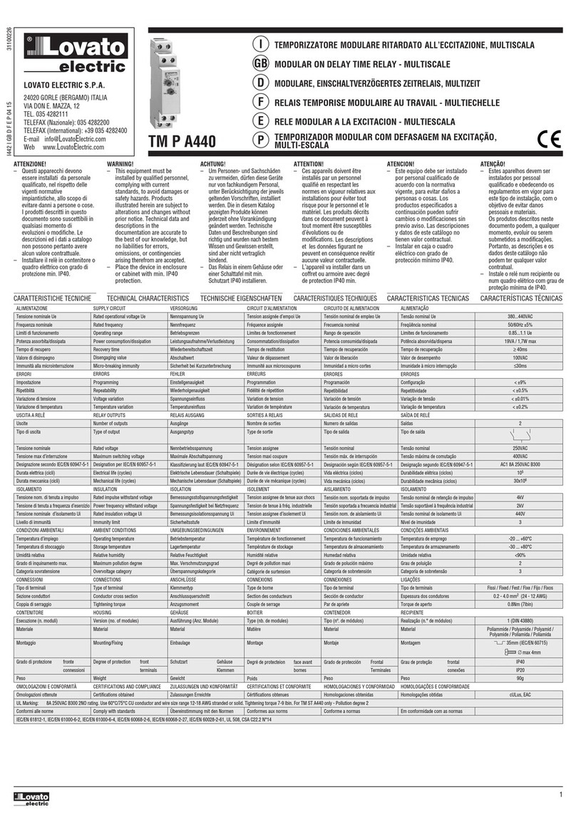
LOVATO ELECTRIC TM P A440 User manual

LOVATO ELECTRIC

LOVATO ELECTRIC TM P A440 User manual

LOVATO ELECTRIC EXS4000 User manual

LOVATO ELECTRIC

LOVATO ELECTRIC EXS4000 User manual

LOVATO ELECTRIC RGK RR User manual

LOVATO ELECTRIC

LOVATO ELECTRIC RGK RR User manual

LOVATO ELECTRIC EXP10 02 User manual

LOVATO ELECTRIC

LOVATO ELECTRIC EXP10 02 User manual

LOVATO ELECTRIC PMA40 User manual

LOVATO ELECTRIC

LOVATO ELECTRIC PMA40 User manual

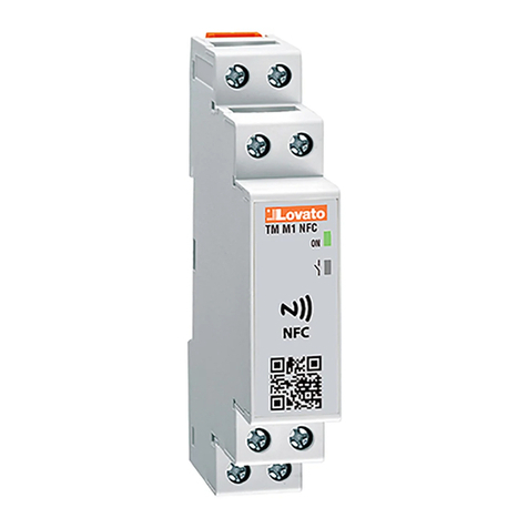
LOVATO ELECTRIC TMM1 NFC User manual

LOVATO ELECTRIC

LOVATO ELECTRIC TMM1 NFC User manual

LOVATO ELECTRIC PMA60 User manual

LOVATO ELECTRIC

LOVATO ELECTRIC PMA60 User manual

LOVATO ELECTRIC PMF20 User manual

LOVATO ELECTRIC

LOVATO ELECTRIC PMF20 User manual

LOVATO ELECTRIC EXP10 03 User manual

LOVATO ELECTRIC

LOVATO ELECTRIC EXP10 03 User manual

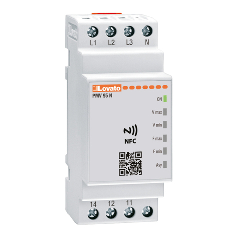
LOVATO ELECTRIC PMV95N***NFC Series User manual

LOVATO ELECTRIC

LOVATO ELECTRIC PMV95N***NFC Series User manual

LOVATO ELECTRIC R1D User manual

LOVATO ELECTRIC

LOVATO ELECTRIC R1D User manual

LOVATO ELECTRIC PMA50 User manual

LOVATO ELECTRIC

LOVATO ELECTRIC PMA50 User manual

LOVATO ELECTRIC RGK RR User manual

LOVATO ELECTRIC

LOVATO ELECTRIC RGK RR User manual

LOVATO ELECTRIC PMA50 User manual

LOVATO ELECTRIC

LOVATO ELECTRIC PMA50 User manual

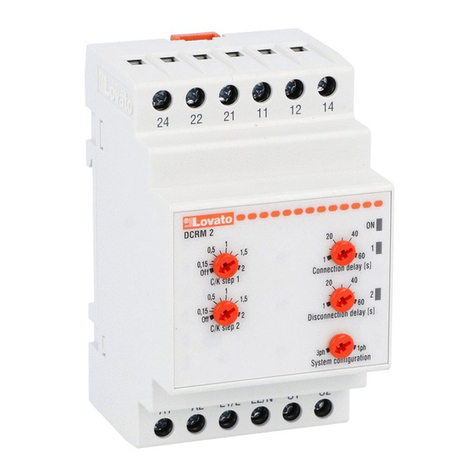
LOVATO ELECTRIC DCRM 2 User manual

LOVATO ELECTRIC

LOVATO ELECTRIC DCRM 2 User manual

LOVATO ELECTRIC PMV55 User manual

LOVATO ELECTRIC

LOVATO ELECTRIC PMV55 User manual

LOVATO ELECTRIC LVM25 User manual

LOVATO ELECTRIC

LOVATO ELECTRIC LVM25 User manual

LOVATO ELECTRIC PMV 50-N User manual

LOVATO ELECTRIC

LOVATO ELECTRIC PMV 50-N User manual

LOVATO ELECTRIC PMVF 10 User manual

LOVATO ELECTRIC

LOVATO ELECTRIC PMVF 10 User manual

LOVATO ELECTRIC SRB Series Instruction Manual

LOVATO ELECTRIC

LOVATO ELECTRIC SRB Series Instruction Manual

Popular Relay manuals by other brands

ABB REJ 525 Operator's manual

ABB

ABB REJ 525 Operator's manual

Pilz PZE X5 operating manual

Pilz

Pilz PZE X5 operating manual

Leuze electronic MSI-SR-LC21DT03 Series Original operating instructions

Leuze electronic

Leuze electronic MSI-SR-LC21DT03 Series Original operating instructions

Eurotherm TE200S user manual

Eurotherm

Eurotherm TE200S user manual

ABB KS Instruction leaflet

ABB

ABB KS Instruction leaflet

Mart BR-11 user manual

Mart

Mart BR-11 user manual

Eaton Cutler-Hammer D64RPY2 A1 Series instruction manual

Eaton

Eaton Cutler-Hammer D64RPY2 A1 Series instruction manual

Siemens Sirius 3UG4621 operating instructions

Siemens

Siemens Sirius 3UG4621 operating instructions

Compact Electric CDMR-62 user manual

Compact Electric

Compact Electric CDMR-62 user manual

Mantracourt T24-RM1 user manual

Mantracourt

Mantracourt T24-RM1 user manual

Rievtech PR-6DC-DA-R user manual

Rievtech

Rievtech PR-6DC-DA-R user manual

Velleman VMB4RY manual

Velleman

Velleman VMB4RY manual

Eaton Cutler-Hammer CEP7 Series Instruction leaflet

Eaton

Eaton Cutler-Hammer CEP7 Series Instruction leaflet

Omron K2CM Series manual

Omron

Omron K2CM Series manual

Elko SMR-K manual

Elko

Elko SMR-K manual

CALEFFI Z-one ZSR101 Series Wiring guide

CALEFFI

CALEFFI Z-one ZSR101 Series Wiring guide

Siemens 3UC50 instructions

Siemens

Siemens 3UC50 instructions

ABB SRW Instruction leaflet

ABB

ABB SRW Instruction leaflet

manuals.online logo
manuals.online logoBrands
  • About & Mission
  • Contact us
  • Privacy Policy
  • Terms and Conditions

Copyright 2025 Manuals.Online. All Rights Reserved.