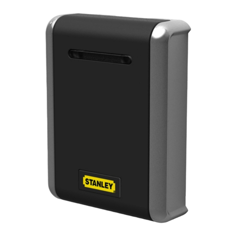
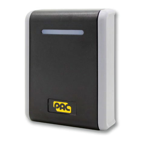
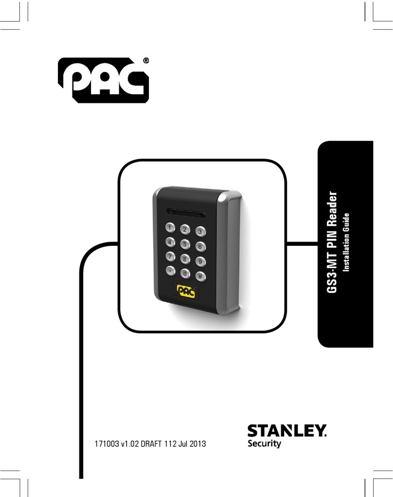
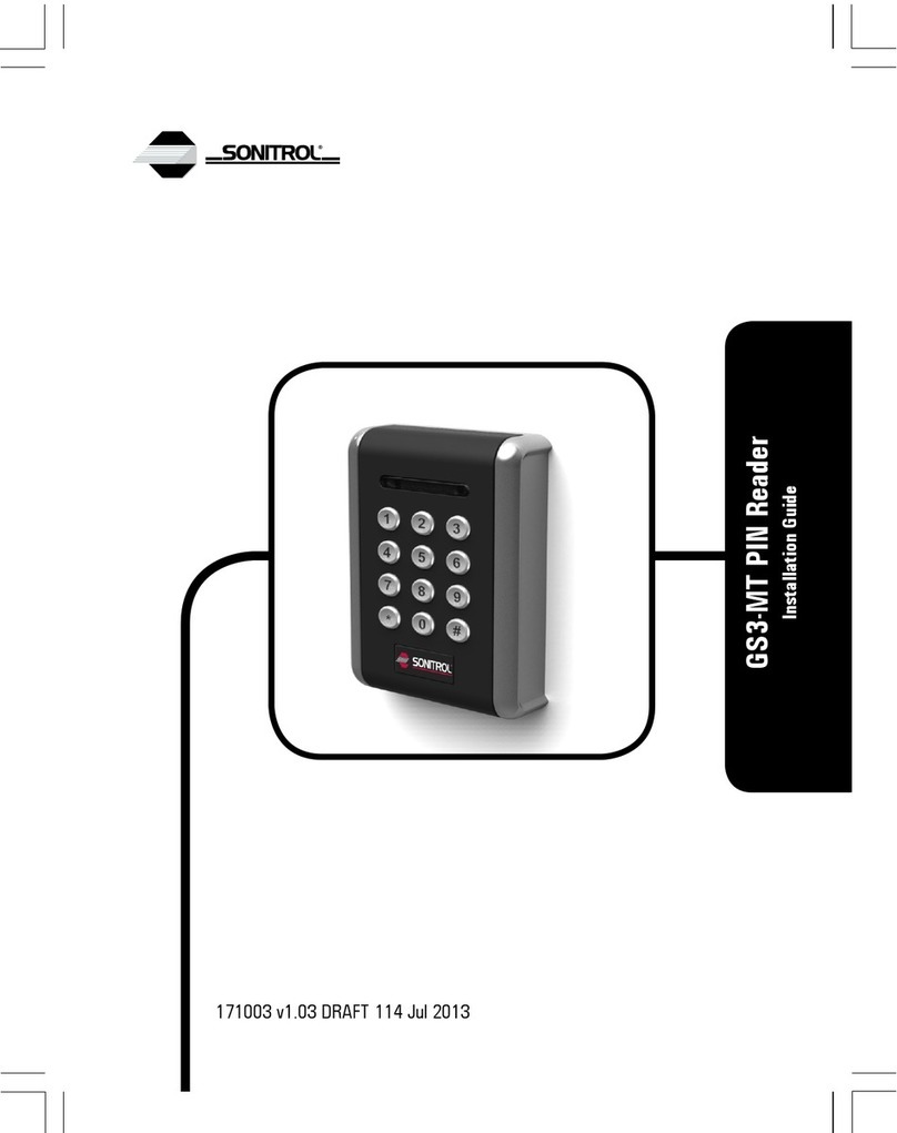
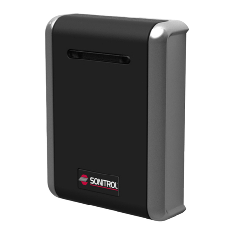
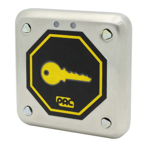
Stanley Oneprox GS3-LF User manual

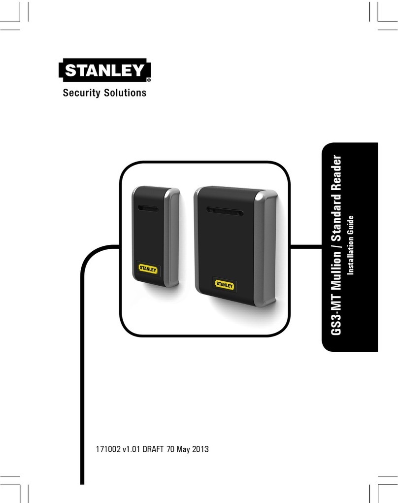
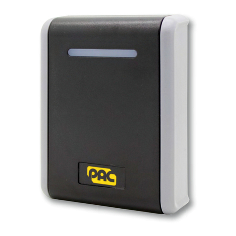
GS3-LF Mullion / Standard Reader
Installation Guide
17998 v3.01 DRAFT 61 Jul 2013

2

GS3-LF Mullion / Standard Reader
Installation Guide
GS3-LF Mittelpfosten / Standard
Installationsanleitung
GS3-LF Lecteur Profilé / Standard
Guide d’installation
GS3-LF Lector Columelar / Estándar
Guía de instalación
GS3-LF Spröjs / Standard
Installationsanvisninar
GS3-LF Mullion / Standaard
Installatiehandleiding
GS3-LF Post / Standard
Installasjonsguide
GS3-LF Stipite / Standard
Guida all’installazione
GS3-LF De parede / Standard
Guia de Instalação
GS3-LF Pystykarmi / Vakio
Asennusopas
3

Standard Reader · Standardleser · Lecteur standard · Lector estándar ·
Standardläsare · Standaard lezer · Standard leser · Lettore standard ·
Leitor standard · Vakiolukija
P/N 909028111
Parts · Teile · Pièces · Piezas · Delar · Delen · Deler · Componenti · Componentes · Osat
×4×1×1
MOV
×1×1×1
Dimensions · Ausmaße · Dimensions · Dimensiones · Mått · Afmetingen · Dimensjoner ·
Dimensioni · Dimensões · Mitat
20.05
13.75
11.5
85.25
11.5
9.97
40.05
60
82.5
110.5
115
89 28
All dimensions mm · Alle Ausmaße in mm · Toutes dimensions en mm · Todas las dimensiones
en mm · Alla mått i mm · Alle afmetingen mm · Alle dimensjoner i mm · Tutte le dimensioni sono
in mm · Todas as dimensões em mm · Kaikki mitat ovat mm:nä
4

Mullion Reader · Mittelpfostenleser · Lecteur profilé · Lector columelar ·
Spröjsläsare · Mullion lezer · Postleser · Lettore per stipite · Leitor de
parede · Pystykarmilukija
P/N 909028110
Parts · Teile · Pièces · Piezas · Delar · Delen · Deler · Componenti · Componentes · Osat
×1×4×1×1×1
MOV
×1
Dimensions · Ausmaße · Dimensions · Dimensiones · Mått · Afmetingen · Dimensjoner ·
Dimensioni · Dimensões · Mitat
48
105
28
20
83
100.5
41.5
25
27.3
30
17.9
All dimensions mm · Alle Ausmaße in mm · Toutes dimensions en mm · Todas las dimensiones
en mm · Alla mått i mm · Alle afmetingen mm · Alle dimensjoner i mm · Tutte le dimensioni sono
in mm · Todas as dimensões em mm · Kaikki mitat ovat mm:nä
5

Connections · Anschlüsse · Connexions · Conexiones · Anslutningar ·
Aansluitingen · Tilkoplingar · Connessioni · Ligações · Liitännät
12-24V
D1/SIG
LED
0V/GND
D0/CLK
TAMP
SOUND
+V / 12V–24V
D1 / SIG
LED
0V / GND
D0 / CLK
Tamper · Sabotage · Effraction · Manip. fraud. · Manip. · Tamper · Sabotasje ·
Manomissione · Interferência · Ilkivalta
Sounder · Signaltongeber · Alarme sonore · Sonido · Ljudsignal · Alarm · Sirene ·
Ricevitore acustico · Dispositivo emissor de sons · Äänimerkinantaja
Do not use · Nicht verwenden · N’utiliser pas · No utilice · Använd inte · Niet
gebruiken · Ikke bruk · Non usare · Não utilizar · Älä käytä
Cable Routing · Kabelführung · Routage du câble · Recorrido del cable ·
Kabeldragning · Kabelroute · Kabelføring · Percorso dei cavi ·
Encaminhamento de cabos · Kaapelireititys
6

Output Format · Ausgabeformat · Format de Sortie · Formato de Salida ·
Utdataformat · Uitvoerformaat · Utdataformat · Formato uscita · Formato
de saída · Lähtömuoto
Default Settings · Standardeinstellungen · Paramètres standards · Ajustes estándares ·
Standardinställningar · Standaardinstellingen · Standardinnstillinger · Impostazioni
standard · Configurações padrões · Oletusasetukset
Output Format
Ausgabeformat
Format de sortie
Formato de Salida
Utdataformat
Uitvoerformaat
Utdataformat
Formato uscita
Formato de saída
Lähtömuoto
Card / Token
Karten / Token
Carte / Fiche
Tarjeta / Ficha
Kort / Nyckel
Kaart / Penning
Kort / Nøkkel
Scheda / Contrassegno
Cartão / Token
Kortti / Rahake
DIP
PAC
ON
1 2 3 4 5
PAC / KeyPAC
Wiegand Prox
PAC 64
ON
1 2 3 4 5
PAC / KeyPAC
Wiegand Prox
Magstripe
ON
1 2 3 4 5
PAC / KeyPAC
Wiegand Prox
7

Other Settings · Andere Einstellungen · Autres paramètres · Otros ajustes · Övriga
inställningar · Andere instellingen · Andre innstillinger · Altre impostazioni · Outras
configurações · Muut asetukset
Output Format
Ausgabeformat
Format de sortie
Formato de Salida
Utdataformat
Uitvoerformaat
Utdataformat
Formato uscita
Formato de saída
Lähtömuoto
Card / Token
Karten / Token
Carte / Fiche
Tarjeta / Ficha
Kort / Nyckel
Kaart / Penning
Kort / Nøkkel
Scheda / Contrassegno
Cartão / Token
Kortti / Rahake
DIP
Wiegand 26-bit
ON
1 2 3 4 5
PAC / KeyPAC
Wiegand Prox
Wiegand 34-bit
ON
1 2 3 4 5
PAC / KeyPAC
Wiegand Prox
Wiegand 74-bit
ON
1 2 3 4 5
PAC / KeyPAC
Wiegand Prox
Wiegand 74-bit
ON
1 2 3 4 5
PAC / KeyPAC
WiegandWiegand Prox
8

Symbols · Symbole · Symboles · Símbolos · Symboler · Symbolen · Symboler · Simboli ·
Símbolos · Symbolit
Data from card · Daten von Karte · Les données de la carte · Los datos de tarjeta ·
Data från kortet · Gegevens van de kaart · Data fra kortet · Dati dalla scheda · Os
dados do cartão · Tiedot kortti
Padded or truncated data · Daten aufgefüllt oder abgeschnitten · Les données sont
complétées ou tronquées · Los datos se rellenan o se truncan · Data utfylls eller
trunkeras · Gegevens worden opgevuld of afgekapt · Data polstres eller avkortes ·
Dati sono imbottiti o troncati · Os dados são preenchidos ou truncados · Tiedot on
pehmustettu tai katkaistu
Processed data · Daten verarbeitet · Les données sont traitées · Los datos se
procesan · Data bearbetas · Gegevens worden verwerkt · Data behandles · Dati
sono trattati · Os dados são processados · Tiedot käsitellään
OPS processed data · Daten verarbeitet als OPS · Les données sont traitées comme
OPS · Los datos se procesan como OPS · Data bearbetas som OPS · Gegevens
worden als OPS verwerkt · Data behandles som OPS · Dati sono trattati come OPS ·
Os dados são processados como OPS · Tiedot käsitellään ja salaus puretaan
9
Reader Configuration · Konfiguration des Lesers · Configuration du
lecteur · Configuración de lector · Läsarens konfigurering ·
Lezerconfiguratie · Leserkonfigurasjon · Configurazione del lettore ·
Configuração do leitor · Lukijan konfiguraatio
Result · Ergebnis · Résultat · Resultado · Resultat · Resultaat · Resultat ·
Risultato · Resultado · Tulos
DIP
Reader beeps when token presented
Der Leser piept, wenn ein Token vorgezeigt wird.
Le lecteur émet un bip lorsque la fiche est présenté
Lector pita cuando una tarjeta es presentada
Läsaren piper när nyckel visas
Lezer piept als een token wordt aangeboden
Leseren piper når symbolet vises
Il lettore emette un segnale acustico quando viene presentato il contrassegno
O leitor emite sinais sonoros quando o token é apresentado
Lukija piippaa laitettaessa rahake laitteeseen
ON
1 2 3 4 5
Reader silent when token presented
Der Leser bleibt stumm, wenn ein Token vorgezeigt wird.
Le lecteur reste silencieux lorsque la fiche est présenté
Lector silencia cuando una tarjeta es presentada
Läsaren är tyst när nyckel visas
Lezer stil als een token wordt aangeboden
Leseren er stille når symbolet vises
Il lettore è silenzioso quando viene presentato il contrassegno
O leitor fica silencioso quando o token é apresentado
Lukija on hiljaa laitettaessa rahake laitteeseen
ON
1 2 3 4 5
10

English
Installation
1. Ensure your product comes with the items indicated on pages 4–5; if not please
contact your branch.
2. Feed cables through backplate.
3. Use two screws to attach backplate to wall.
4. Use two screws to attach tamper plate to wall.
5. Connect cable to circuit board — see page 6.
6. Set output format — see page 7.
7. Configure reader — see page 10.
8. Snap reader to backplate and secure with final screw.
9. Apply power when all readers are installed.
Notes
•If power is applied when the reader is not properly attached to the wall, a wall
tamper condition is generated.
•Do not distort the back plate or tamper plate when mounting, e.g. to a back box,
or a spurious wall tamper / case tamper condition may be generated.
•Mount readers >3′ / 1m apart, e.g. on either side of the door. Mounting on metal
surfaces will reduce the reading range.
•If the reader is being used to enter credential information to arm a system, the
reader must be located within 3′ / 1m of the panel’s main keypad or display.
•For outside readers, use corrosion-resistant fixings and apply silicone sealant to
the backplate before fixing to the wall.
•The supplied MOV (Metal Oxide Varistor, Anglia Components P/N B72207S250K101)
should be fitted across the power terminals of the lock to suppress back EMF. Any
suppression diodes fitted in the lock / lock circuit must be removed.
•Output format and reader configuration can be changed without disconnecting the
power supply. The reader automatically restarts with the new configuration.
11
English

Reader Tamper
If the backplate is pulled away from the wall, the tamper plate remains attached to the wall
and a wall tamper condition is generated. Likewise, if the reader is removed from the backplate,
acase tamper condition is generated.
The voltage on the Tamper line is normally low. If case tamper or wall tamper is detected, the
voltage on the Tamper line becomes high and the reader sounds 3 long beeps every 5 seconds
for two minutes, then stops.
To clear a wall tamper condition, reattach the backplate to the tamper plate. To clear a case
tamper condition, reattach the reader to the backplate.
Usage
LEDs
YellowRed / GreenGreenRed
Not usedAccess deniedAccess permittedDefault
Sounder
•The reader sounds 4 rapid beeps when it is powered up or restarted.
•If specified, the reader beeps once when a token is presented.
Cable Lengths
PAC door controllers only
Distance from Reader to ControllerCable Gauge
AC 202 / 512AC 2100 / 2200
230′ / 70m *750′ / 250m7/0.2 0.34mm² 22AWG
230′ / 70m *1500′ / 500m16/0.2 0.5mm² 20AWG
230′ / 70m *3000′ / 1000m32/0.2 1.0mm² 18AWG
12
English

Notes
•These figures (*) are for readers powered from the controller. The cable distances
can be increased to 1650′ / 500m by locally powering the readers.
•Locally powered readers must be connected to a UL 603 power limited Class 2
supply for US, or a ULC S318 power limited Class 2 supply for Canada.
•If you use 22AWG / 0.34mm² cables, twist the wires and double them over before
inserting them in the crimps.
•Maximum cable distances will be less for readers which have been set to give
Wiegand output.
Specification
CurrentPowerReader Range
100mA (Mullion) / 120mA
(Standard)
12V–24V DCUp to 4.0″ / 100mm
Note
Maximum current draw is lower at 24V.
Temperature
StorageOperating
-40°C — +66°C / -40°F — +151°F-40°C — +66°C / -40°F — +151°F
Humidity
Operating for 24 hours
Tested at 93% for ULC S319.10-85% RH @ 30±2°C / 85±4°F
Ingress Protection
IP65 after installation — evaluated by lab separate from UL. Installer must adequately seal any
connections made.
Weight
150g (Mullion) / 290g (Standard)
13
English

Deutsch
Installation
1. Überprüfen Sie, ob Ihr Produkt die Einzelteile angezeigt auf Seiten 4–5; wenn nicht,
wenden Sie sich bitte an Ihren Zweigstelle.
2. Kabel durch die Rückseite schieben.
3. Rückplatte mit zwei Schrauben an der Wand befestigen.
4. Sicherheitsplatte mit zwei Schrauben an der Wand befestigen.
5. Kabel mit der Platine verbinden — siehe Seite 6.
6. Ausgabeformat einstellen — siehe Seite 7.
7. Leser konfigurieren — siehe Seite 10.
8. Leser an der Rückplatte einschnappen lassen und mit einer letzten Schraube sichern.
9. Strom erst anlegen, wenn alle Leser installiert sind.
Hinweise
•Falls der Strom angelegt wird, bevor der Leser korrekt an der Wand befestigt ist,
wird ein Wandmanipulationsalarm ausgeben.
•Nicht zulassen, dass sich die Rückseite oder Sicherheitsplatte bei der Montage z. B.
an einem Rückkasten verzieht. Dies kann zu falschen Wand- / Gehäusemanipulations-
alarmen führen.
•Leser im Abstand von > 1 m anbringen.
•Wird der Leser verwendet, um Zugangsinformationen zur Aktivierung eines Systems
einzugeben, muss sich der Leser innerhalb eines Umkreises von 1m um das Tastenfeld
oder die Anzeige des Panels befinden.
•Für Leser im Freien sind korrosionsbeständige Befestigungselemente und
Silikondichtungsmittel an den Anschlüssen verwenden.
•Der MOV sollte über den Stromanschlüssen des Schlosses montiert werden.
•Das Ausgabeformat und die Leserkonfiguration können geändert werden, ohne die
Stromversorgung zu unterbrechen. Der Leser startet automatisch erneut mit der
neuen Konfiguration.
14
Deutsch

Sabotage des Lesers
Wird die Rückplatte von der Wand getrennt, bleibt die Sicherheitsplatte an der Wand hängen
und ein Wandmanipulationsalarm wird ausgegeben. Falls der Leser von der Rückplatte
entfernt wird, wird ein Gehäusemanipulationsalarm ausgegeben.
Die Manipulationsschutzleitung führt normalerweise eine geringe Spannung. Falls eine Gehäuse-
oder Wandmanipulation erkannt wird, steigt die Spannung in der Manipulationsschutzleitung
an. Der Leser gibt zwei Minuten lang alle 5 Sekunden 3 lange Pieptöne aus und verstummt
dann.
Um den Wandmanipulationsalarm abzuschalten, befestigen Sie die Rückplatte wieder an der
Sicherheitsplatte. Um den Gehäusemanipulationsalarm abzuschalten, befestigen Sie den Leser
wieder an der Rückplatte.
Verwendung
LEDs
GelbRot / GrünGrünRot
Nicht verwendetZutritt verweigertZutritt gestattetStandard
Signaltongeber
•Der Leser gibt 4 schnelle Pieptöne aus, wenn er eingeschaltet oder neu gestartet
wird.
•Falls vorgegeben, piept der Leser einmal, wenn ein Token angezeigt wird.
Kabellängen
Nur PAC Türkontroller
Maximale Distanz zwischen Leser und KontrollerKabeltyp
AC 202 / 512AC 2100 / 2200
230′ / 70m *750′ / 250m7/0.2 0.34mm² 22AWG
230′ / 70m *1500′ / 500m16/0.2 0.5mm² 20AWG
230′ / 70m *3000′ / 1000m32/0.2 1.0mm² 18AWG
15
Deutsch

Hinweise
•Diese Werte (*) basieren auf der Annahme, dass der Leser über den Controller mit
Strom versorgt wird. Die Kabel können bis 500m durch eine lokale Stromversorgung
des Lesers verlängert werden.
•Leser mit örtlicher Stromversorgung müssen in den USA an einem
leistungsbegrenzten UL 603-Netzteil der Klasse 2 und in Kanada an einem
leistungsbegrenzten ULC S318-Netzteil der Klasse 2 angesteckt werden.
•Bei Nutzung eines 22AWG / 0.34mm² Kabels, verdrillen Sie die Drähte und doppeln
Sie diese bevor Sie die Enden in die Steckverbindungen einführen.
•Maximale Kabellängen können kürzer sein bei Lesern die als Wiegand-Leser
angebunden sind an den Kontroller.
Spezifikation
StromSpannungLeserbereich
100mA (Mullion) / 120mA
(Standard)
12V–24V DCBis 100 mm
Hinweis
Maximum current draw is lower at 24V.
Temperatur
LagerungBetrieb
-40°C — +66°C-40°C — +66°C
Feuchtigkeit
Betrieb für 24 Stunden
Geprüft bei 93% für ULC S31910-85% RH @ 30±2°C / 85±4°F
Eindringschutz
IP65-Norm, komplett vergossen. Errichter müssen alle neuen Verbindungen ebenfalls versiegeln.
Weight
150g (Mullion) / 290g (Standard)
16
Deutsch

Français
Installation
1. Vérifier que votre produit contient toutes les articles indiqués à les pages 4–5. En cas
de pièce manquante, contacter votre succursale.
2. Passer les câbles à travers le support de fixation.
3. Utiliser deux vis pour fixer le support de fixation au mur.
4. Utiliser deux vis pour fixer le support d’autoprotection au mur.
5. Raccorder le câble au circuit — voir page 6.
6. Sélectionner le format de sortie — voir page 7.
7. Configurer le lecteur — voir page 10.
8. Fixer fermement le lecteur à son support de fixation et assurer la fixation avec la dernière
vis.
9. Alimenter le système une fois que tous les lecteurs ont été installés.
17
Français

Remarques
•Si le lecteur n’est pas fixé correctement au mur, une alarme arrachement est émise.
•Ne pas déformer le support de fixation ou le support d’autoprotection lors de
linstallation sur une paroi ou bien sur un mur inégal, sous risque d’alarme.
•Monter les lecteurs à de telle sorte qu’ils soient espacés d’1m, par exemple de
chaque coté de la porte. L’installation sur une surface métallique réduit la distance
de lecture.
•Si le lecteur est utilisé pour entrer les informations d’identification pour armer un
système, le lecteur doit être placé à moins de 1 m du clavier principal ou de
l’afficheur.
•Pour les lecteurs extérieurs, utiliser des fixations résistantes à la corrosion et
appliquer du silicone sur le support de fixation avant de le fixer au mur.
•Le MOV (varistor à oxyde métallique, Anglia Components nº B72207S250K101)
doit être installé en travers des bornes d’alimentation la serrure pour éviter le risque
de retour électrique. Toute diode ou self de blocage doivent être retirés.
•Le format de sortie et la programmation du lecteur peuvent être modifiés sans
couper l’alimentation. Le lecteur redémarre automatiquement avec la nouvelle
programmation.
Autoprotection du lecteur
Si le support de fixation est écarté du mur, le support d’autoprotection reste fixé au mur, et
une alarme d’arrachement est émise. De la même façon si le lecteur est retiré de son support
de fixation, une alarme d’ouverture du lecteur est émise.
La tension sur la borne d’autoprotection est nulle au repos. Si une autoprotection à l’arrachement
ou à l’ouverture est émise, une tension apparaît sur le circuit d’autoprotection et le lecteur
émet 3 bips longs toutes les 5 secondes pendant 2 minutes, puis s’arrête.
Pour annuler l’autoprotection à l’arrachement, refixer le support de fixation au support
d’autoprotection. Pour annuler l’autoprotection à l’ouverture, refixer le lecteur à son support
de fixation.
Utilisation
Diodes
JauneRouge / VertVertRouge
Non utiliséAccès refuséAccès autoriséPar défaut
18
Français

Alarme sonore
•L’alarme sonore émet 4 bips courts lorsque le lecteur est alimenté ou redémarre.
•Si la fonction a été paramétrée, le lecteur émet un bip lorsque la fiche est présenté.
Longueur des câbles
Seulement pour les contrôleurs PAC.
Distance du lecteur au contrôleurÉpaisseur du câble
AC 202 / 512AC 2100 / 2200
230′ / 70m *750′ / 250m7/0.2 0.34mm² 22AWG
230′ / 70m *1500′ / 500m16/0.2 0.5mm² 20AWG
230′ / 70m *3000′ / 1000m32/0.2 1.0mm² 18AWG
Remarques
•Ces données (*) sont pour les lecteurs qui sont branches au contrôleur. La longueur
des câbles peut être augmentée de 500m si les lecteurs sont branches sur place.
•Pour les lecteurs qui sont branches sur place, l’alimentation doit être de classe 2,
limité en puissance, au conforme de l’UL 603 pour les USA; ou de classe 2, limité
en puissance, au conforme de l’ULC S318 pour le Canada.
•Si un câble 22AWG / 0.34mm² est utilise, plier les fils électriques en deux avant de
les insérer dans les sertisseurs.
•La longueur maximum des câbles sera moindre pour les lecteurs avec Wiegand.
Spécification
CourantAlimentationPortée du lecteur
100mA (Mullion) / 120mA
(Standard)
12V–24V DCJusqu’à 100mm
Remarque
Maximum current draw is lower at 24V.
Température
RangementEn opération
-40°C — +66°C-40°C — +66°C
19
Français

Humidité
En opération pendant 24 heures
Testé à 93% pour l’ULC S319.10-85% RH @ 30±2°C / 85±4°F
Protection contre l’entrée
IP65 après l’installation. Toutes connexions doivent être étanches par l’installateur.
Weight
150g (Mullion) / 290g (Standard)
20
Français
Other manuals for Oneprox GS3-LF
3
Table of contents
Languages:
Other Stanley Card Reader manuals

Stanley
Stanley GS3LFM User manual

Stanley
Stanley 909020113 User manual

Stanley
Stanley GS3-MT User manual

Stanley
Stanley PAC GS3LFV User manual

Stanley
Stanley Oneprox GS3-LF User manual

Stanley
Stanley Sonitrol GS3MTS User manual

Stanley
Stanley RoamAlert User manual

Stanley
Stanley PAC GS3-LF User manual

Stanley
Stanley Sonitrol GS3LFS User manual

Stanley
Stanley PAC GS3LFS User manual