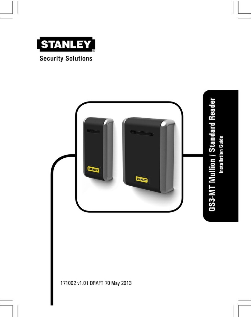
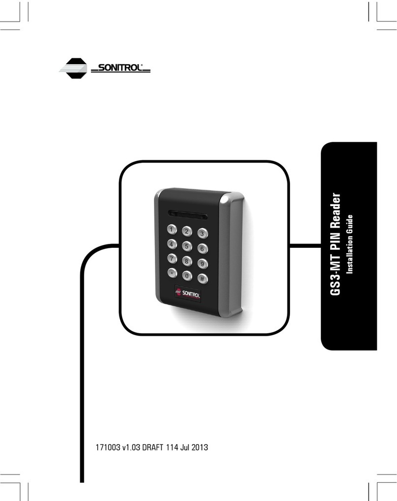
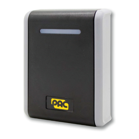
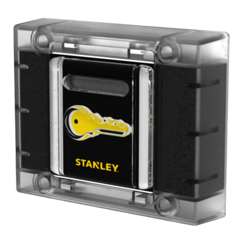
Stanley Sonitrol GS3LFV User manual

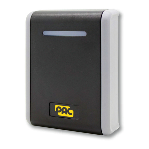
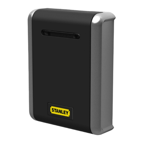
GS3-LF Vandal Reader
Installation Guide
171005 v1.03 DRAFT 59 Jul 2013

2

Parts · Pièces · Piezas
P/N 909070116
×4×1×1
MOV
×1×1
×1
Dimensions · Dimensions · Dimensiones
100
100 16 70
70
46.3
35
19.88
21.15
Ø 13
Ø 10
All dimensions mm · Toutes dimensions en mm · Todas las dimensiones en mm
4

Connections · Connexions · Conexiones
+V / 12V–24VRed · Rouge · Rojo
D1 / SIGWhite · Blanc · Blanco
LEDBrown · Marron · Marrón
0V / GNDBlack · Noir · Negro
D0 / CLKGreen · Vert · Verde
Tamper · Effraction · Manip. fraud.Blue · Bleu · Azul
Sounder · Alarme sonore · SonidoYellow · Jaune · Amarillo
Do not use · N’utiliser pas · No utiliceOrange · Orange · Naranja
5

Output Format · Format de Sortie · Formato de Salida
Default Settings · Paramètres standards · Ajustes estándares
Output Format
Format de sortie
Formato de Salida
Card / Token
Carte / Fiche
Tarjeta / Ficha
DIP
Wiegand 74-bit
ON
1 2 3 4 5
PAC / KeyPAC
WiegandWiegand Prox
Wiegand 34-bit
ON
1 2 3 4 5
PAC / KeyPAC
Wiegand Prox
Wiegand 26-bit
ON
1 2 3 4 5
PAC / KeyPAC
Wiegand Prox
Wiegand 74-bit
ON
1 2 3 4 5
PAC / KeyPAC
Wiegand Prox
Other Settings · Autres paramètres · Otros ajustes
Output Format
Format de sortie
Formato de Salida
Card / Token
Carte / Fiche
Tarjeta / Ficha
DIP
Magstripe
ON
1 2 3 4 5
PAC / KeyPAC
Wiegand Prox
PAC
ON
1 2 3 4 5
PAC / KeyPAC
Wiegand Prox
PAC 64
ON
1 2 3 4 5
PAC / KeyPAC
Wiegand Prox
6

Symbols · Symboles · Símbolos
Data from card · Les données de la carte · Los datos de tarjeta
Padded or truncated data · Les données sont complétées ou tronquées · Los datos
se rellenan o se truncan
Processed data · Les données sont traitées · Los datos se procesan
OPS processed data · Les données sont traitées comme OPS · Los datos se procesan
como OPS
7

Reader Configuration · Configuration du lecteur · Configuración de
lector
Result · Résultat · ResultadoDIP
Reader beeps when token presented
Le lecteur émet un bip lorsque la fiche est présenté
Lector pita cuando una tarjeta es presentada
ON
1 2 3 4 5
Reader silent when token presented
Le lecteur reste silencieux lorsque la fiche est présenté
Lector silencia cuando una tarjeta es presentada
ON
1 2 3 4 5
8

English
Installation
1. Ensure your product comes with the items indicated on page 4; if not please contact
your dealer.
2. Drill a 1 ⁄ 2” or 13mm diameter hole for the tamper magnet — see page 4.
3. Push the tamper plug into the hole, then insert the tamper magnet.
4. Drill a 13 ⁄ 32” or 10mm diameter hole for the flying lead — see page 4.
5. Connect the flying lead — see page 5.
6. Set output format — see page 6.
7. Configure reader — see page 8.
8. Use the supplied vandal resistant screws to attach the reader to the wall. These require
a special screwdriver (P/N 1950), available separately.
9. Apply power when all readers are installed.
Notes
•If power is applied when the tamper magnet is not positioned correctly, a reader
tamper condition is generated and the reader beeps.
•Mount readers >3′ / 1m apart, e.g. on either side of the door. Mounting on metal
surfaces will reduce the reading range.
•If the reader is being used to enter credential information to arm a system, the
reader must be located within 3′ / 1m of the panel’s main keypad or display.
•For outside readers, use corrosion-resistant fixings and apply silicone sealant to
the backplate before fixing to the wall.
•The supplied MOV (Metal Oxide Varistor, Anglia Components P/N B72207S250K101)
should be fitted across the power terminals of the lock to suppress back EMF. Any
suppression diodes fitted in the lock / lock circuit must be removed.
•Output format and reader configuration can be changed without disconnecting the
power supply. The reader automatically restarts with the new configuration.
9
English
Reader Tamper
If the reader is pulled away from the wall, the tamper plug remains attached to the wall and
areader tamper condition is generated.
The voltage on the Tamper line is normally low. If reader tamper is detected, the voltage on
the Tamper line becomes high and the reader sounds 3 long beeps every 5 seconds for two
minutes, then stops.
To clear a reader tamper condition, reattach the reader to the wall.
Usage
LEDs
Red / GreenGreenRed
Access deniedAccess permittedDefault
Sounder
•The reader sounds 4 rapid beeps when it is powered up or restarted.
•If specified, the reader beeps once when a token is presented.
Cable Lengths
Sonitrol door controllers only
Distance from Reader to ControllerCable Gauge
230′ / 70m *7/0.2 0.34mm² 22AWG
230′ / 70m *16/0.2 0.5mm² 20AWG
230′ / 70m *32/0.2 1.0mm² 18AWG
Notes
•These figures (*) are for readers powered from the controller. The cable distances
can be increased to 1650′ / 500m by locally powering the readers.
•Locally powered readers must be connected to a UL 603 power limited Class 2
supply for US, or a ULC S318 power limited Class 2 supply for Canada.
•If you use 22AWG / 0.34mm² cables, twist the wires and double them over before
inserting them in the crimps.
•Maximum cable distances will be less for readers which have been set to give
Wiegand output.
10
English

Specification
CurrentPowerReader Range
90mA12V–24V DCUp to 4.0″ / 100mm
Note
Maximum current draw is lower at 24V.
Temperature
StorageOperating
-40°C — +66°C / -40°F — +151°F-40°C — +66°C / -40°F — +151°F
Humidity
Operating for 24 hours
Tested at 93% for ULC S319.10-85% RH @ 30±2°C / 85±4°F
Ingress Protection
IP67 after installation — evaluated by lab separate from UL. Installer must adequately seal any
connections made.
Weight
410g (inc. flying lead) / 330g (not inc. flying lead)
11
English
Français
Installation
1. Vérifier que votre produit contient toutes les articles indiqués à la page 4. En cas de
pièce manquante, contacter votre distributeur.
2. Percer un trou d’un diamètre de 13 mm pour l’aimant d’autoprotection — voir page 4.
3. Enfoncer le bouchon dans le trou, puis insérer l’aimant d’autoprotection.
4. Percer un trou d’un diamètre de 10 mm pour le fil — voir page 4.
5. Raccorder le fil — voir page 5.
6. Sélectionner le format de sortie — voir page 6.
7. Configurer le lecteur — voir page 8.
8. Attacher le lecteur sur le mur en utilisant les vis anti-vandalisme fournies. Un tournevis
spécial est nécessaire (nº 1950), séparément en vente.
9. Alimenter le système une fois que tous les lecteurs ont été installés.
Remarques
•Si l’aimant d’autoprotection n’est pas correctement positionné, une alarme
d’arrachement est émise lorsque le lecteur est alimenté.
•Monter les lecteurs à de telle sorte qu’ils soient espacés d’1m, par exemple de
chaque coté de la porte. L’installation sur une surface métallique réduit la distance
de lecture.
•Si le lecteur est utilisé pour entrer les informations d’identification pour armer un
système, le lecteur doit être placé à moins de 1 m du clavier principal ou de
l’afficheur.
•Pour les lecteurs extérieurs, utiliser des fixations résistantes à la corrosion et
appliquer du silicone sur le support de fixation avant de le fixer au mur.
•Le MOV (varistor à oxyde métallique, Anglia Components nº B72207S250K101)
doit être installé en travers des bornes d’alimentation la serrure pour éviter le risque
de retour électrique. Toute diode ou self de blocage doivent être retirés.
•Le format de sortie et la programmation du lecteur peuvent être modifiés sans
couper l’alimentation. Le lecteur redémarre automatiquement avec la nouvelle
programmation.
12
Français

Autoprotection du lecteur
Si le lecteur est écarté du mur, le bouchon d’autoprotection reste fixé au mur, et une alarme
d’arrachement est émise.
La tension sur la borne d’autoprotection est nulle au repos. Si une autoprotection à l’arrachement
est émise, une tension apparaît sur le circuit d’autoprotection et le lecteur émet 3 bips longs
toutes les 5 secondes pendant 2 minutes, puis s’arrête.
Pour annuler l’autoprotection à l’arrachement, refixer le lecteur au mur.
Utilisation
Diodes
Rouge / VertVertRouge
Accès refuséAccès autoriséPar défaut
Alarme sonore
•L’alarme sonore émet 4 bips courts lorsque le lecteur est alimenté ou redémarre.
•Si la fonction a été paramétrée, le lecteur émet un bip lorsque la fiche est présenté.
Longueur des câbles
Seulement pour les contrôleurs Sonitrol.
Distance du lecteur au contrôleurÉpaisseur du câble
230′ / 70m *7/0.2 0.34mm² 22AWG
230′ / 70m *16/0.2 0.5mm² 20AWG
230′ / 70m *32/0.2 1.0mm² 18AWG
Remarques
•Ces données (*) sont pour les lecteurs qui sont branches au contrôleur. La longueur
des câbles peut être augmentée de 500m si les lecteurs sont branches sur place.
•Pour les lecteurs qui sont branches sur place, l’alimentation doit être de classe 2,
limité en puissance, au conforme de l’UL 603 pour les USA; ou de classe 2, limité
en puissance, au conforme de l’ULC S318 pour le Canada.
•Si un câble 22AWG / 0.34mm² est utilise, plier les fils électriques en deux avant de
les insérer dans les sertisseurs.
•La longueur maximum des câbles sera moindre pour les lecteurs avec Wiegand.
13
Français

Spécification
CourantAlimentationPortée du lecteur
90mA12V–24V DCJusqu’à 100mm
Remarque
Maximum current draw is lower at 24V.
Température
RangementEn opération
-40°C — +66°C-40°C — +66°C
Humidité
En opération pendant 24 heures
Testé à 93% pour l’ULC S319.10-85% RH @ 30±2°C / 85±4°F
Protection contre l’entrée
IP67 après l’installation. Toutes connexions doivent être étanches par l’installateur.
Weight
410g (inc. flying lead) / 330g (not inc. flying lead)
14
Français

Español
Instalación
1. Asegure que el producto se suministra con los artículos indicados en la página 4; en caso
contrario, rogamos que se ponga en contacto con el vendedor.
2. Perfore un orificio de 13 mm de diámetro para el imán de manipulación — consulte la página
4.
3. Empuje la clavija de manipulación hacia el orificio y, a continuación, introduzca el imán de
manipulación.
4. Perfore un orificio de 10 mm de diámetro para el cable flexible — consulte la página 4.
5. Conecte el cable flexible — consulte la página 5.
6. Establecer formato de salida — ver página 6.
7. Configurar el lector — ver página 8.
8. Utilice los tornillos a prueba de agresiones para fijar el lector a la pared. Estos tornillos
requieren un destornillador especial (Ref. 1950), disponible por separado.
9. Aplique alimentación cuando todos los lectores están instalados.
15
Español

Notas
•Si la energía se aplica cuando el imán de manipulación no está colocado
correctamente, una condición de sabotage se genera.
•Monte los lectores a una distancia entre sí >1 m, por ejemplo a cada lado de la
puerta. Montaje en superficies metálicas reducirá el rango de lectura.
•Si el lector está siendo utilizado para introducir la información de credenciales para
armar un sistema, el lector debe estar situado dentro de un rango de 1m del teclado
principal del panel o la pantalla.
•Para los lectores exteriores, utilice fijaciones anticorrosivas y sellador de silicona
en la placa de montaje antes de fijarlo a la pared.
•El MOV (varistor de metal-óxido, Anglia Components nº B72207S250K101) se
debería montar a través de los terminales de potencia de la cerradura para suprimir
un retorno de corriente. Todos los diodos de supresión instalados en el cerradero o
el circuito del cerradero deben ser eliminado.
•El formato de salida y la configuración de lector pueden ser cambiado sin
desconectar la fuente de alimentación. El lector se reinicia automáticamente con la
nueva configuración.
Manipulación fraudulenta de lector
Si el lector se separa de la pared, el tapón de manipulación permanece unida a la pared
y una condición de sabotaje se genera.
La tensión en la línea de sabotaje es normalmente baja. Si el sabotaje se detectan, la tensión en
la línea de sabotaje se convierte en alta y el lector emite 3 pitidos largos cada 5 segundos durante
dos minutos, luego se detiene.
Para borrar una condición de sabotaje, vuelva a colocar el lector a la pared.
Uso
LEDs
Rojo / VerdeVerdeRojo
Acceso denegadoAcceso permitidoPor defecto
Sonido
•El lector emite 4 pitidos rápidos cuando el lector se alimenta o se reinicia.
•Si se especifica, el lector suena una vez cuando una tarjeta es presentada.
16
Español

Longitudes del Cable
Solo válida para controladoras Sonitrol.
Distancia desde el Lector a ControladorGrosor del Cable
230′ / 70m *7/0.2 0.34mm² 22AWG
230′ / 70m *16/0.2 0.5mm² 20AWG
230′ / 70m *32/0.2 1.0mm² 18AWG
Notas
•Estos datos (*) son válidos para lectores alimentados desde la controladora. Las
distancias del cable pueden ser incrementadas a 500m utilizando lectores con
alimentación local.
•Los lectores de alimentación local deben ser conectados a una fuente de alimentación
limitadas clase 2 UL603 para USA, o a una fuente de alimentación limitada clase
2 ULC S318 para Canadá.
•Si se usa un cable de 22AWG / 0.34mm² retorcer los cables y doblarlos para
insertarlos en un terminal.
•La máxima distancia de cable será menor para los lectores los cuales hayan sido
configurados para dar una salida Wiegand.
Especificaciones
CorrienteAlimentaciónRango del lector
90mA12V–24V DCHasta 100mm
Nota
Maximum current draw is lower at 24V.
Temperatura
AlmacenamientoOperando
-40°C — +66°C-40°C — +66°C
17
Español

Humedad
Operando para 24 horas
Testado al 93 % según ULC S319.10-85% RH @ 30±2°C / 85±4°F
Protección de Acceso
Hermetizar para IP67 después de la instalación. El instalador debe hermetizar y proteger cualquier
conexión que se haga.
Weight
410g (inc. flying lead) / 330g (not inc. flying lead)
18

UL / ULC Outdoor / Indoor rated.
•UL 294 5th Ed. Attack Class 3 — Access Control Systems Unit
•ULC S319-05 Class 3 — Electronic Access Control Systems
•UL 1610 — Central-Station Burglar-Alarm Units
•ULC S304 — Central and Monitoring Station Burglar Alarm Units
•UL 1076 — Proprietary Burglar Alarm Units and Systems
•ULC C1076 — Proprietary Burglar Alarm Units and Systems
•UL 609 — Local Burglar Alarm Units and Systems
•ULC S303 — Standards for Local Burglar Alarm Units and Systems
Notes
•This product’s compliance to ULC S319 will be invalidated through the use of any
add-on, expansion, memory, or other module manufactured or supplied by the
manufacturer or manufacturer’s representative.
•For UL 609 the reader is not to be used for low battery indication and audible exit /
entry delay. The Listed approved keypad is to be used to display these functions.
•This product cannot be used to receive or display acknowledgment signals from
central station.
19

Declaration of Conformity is available on request.
In addition to meeting the minimum CE requirements, this product has been tested to the
following:
•EN 50131 — Security Grade 3, Environmental Class IVA, Type A Fixed Device (per
EN 50131-3)
•EN 50133 — Access Point Reader, Recognition Class 2, Environmental Class IIIA,
IP67, IK 04
EN 50130-4 (per 50131 and 50133)
EN 50130-5 (per 50131 and 50133)
Do not discard this product along with other household waste; it must be collected and treated
separately.
20
This manual suits for next models
1
Table of contents
Languages:
Other Stanley Card Reader manuals

Stanley
Stanley PAC GS3-LF User manual

Stanley
Stanley Oneprox GS3-LF User manual

Stanley
Stanley Sonitrol GS3LFS User manual

Stanley
Stanley PAC GS3-MT User manual

Stanley
Stanley Sonitrol GS3MTM User manual

Stanley
Stanley Sonitrol GS3MTS User manual

Stanley
Stanley RoamAlert User manual

Stanley
Stanley PAC GS3LFV User manual

Stanley
Stanley PAC GS3LFS User manual

Stanley
Stanley Oneprox GS3-LF User manual