Star SP700 Series User manual

DOT MATRIX PRINTER
SP700 Series
[ 9 Wire Print Head ]
Technical Manual
< FIRST EDITION >

NOTICE
All rights reserved. Reproduction of any part of this manual in any form whatsoever, without
STAR’s express permission is forbidden.
e contents of this manual are subject to change without notice.
All eorts have been made to ensure the accuracy of the contents of this manual at the time of
going to press. However, should any errors be detected, STAR would greatly appreciate being
informed of them.
e above notwithstanding, STAR can assume no responsibility for any errors in this manual.
© Copyright 2007 Star Micronics Co.,Ltd.
•
•
•
•

INTRODUCTION
is manual describes the thermal printer SP700 series.
It is designed for use as a reference for periodic inspections and maintenance procedures to be executed
by service personnel. It is not intended for the general user. Users of this manual should have a basic
knowledge and understanding of the English language.
• is manual is divided into the following sections:
Chapter 1 Adjustments
Chapter 2 Parts Replacement
Chapter 3 Maintenance and Lubrication
Chapter 4 Parts List
• First edition : May 2007
1
3
2
4

CHAPTER 1
ADJUSTMENTS
is printer has undergone various adjustments so that it will attain a given standard of performance.
In this chapter, a brief explanation is given of the methods for making adjustments.
Follow the instructions when performing maintenance inspections or when replacing parts to correct
malfunctions.
1. Adjusting the Print Head and Platen Gap . . . . . . . . . . . . . . . . . . . . . . . . . .2
1-1. Measuring the Print Head and Platen Gap . . . . . . . . . . . . . . . . . . . . . . . 2
1-2. Adjusting the Print Head and Platen . . . . . . . . . . . . . . . . . . . . . . . . . . . . 3
2.AdjustingtheBeltTension .......................................4
3.AdjustingthePaperFeedPath....................................5
4. Adjusting the Printing Dot Mis-positioning . . . . . . . . . . . . . . . . . . . . . . . .6
5.AdjustingtheBlackMarkSensor .................................8
1

1. Adjusting the Print Head and Platen Gap
1-1. Measuring the Print Head and Platen Gap
See sections 2 and 3 for details on how to remove the
tear bar.
Insert a thickness gauge [3] between the print head [1]
and platen [2] to measure the gap.
Measure the le, right and center of the platen (in the
printing region). e standard for the gap is between 0.40
and 0.45mm.
If the gap is not at the standard value, see page 1-2 to
adjust the gap.
1.
2.
3.
- 2 -
[ 1 ] [ 3 ]
[ 2 ]
Fig. 1-1 Measuring the Gap

1-2. Adjusting the Print Head and Platen
To adjust the le side gap, remove the adjustment
bushing [4] screw in the le side frame and move the
adjustment bushing [4] up and down.
1.
To adjust the right side gap, remove the adjustment
bushing [5] screw in the right side frame and move the
adjustment bushing [5] up and down.
Measure the gap as described in 1-1 above.
If the measurement value is not with 0.4 to 0.45, repeat
steps 1 and 2.
If the adjustment is within that range, tighten the screws
you loosened or removed.
2.
3.
4.
5.
- 3 -
Gap
-
+
[5]
[4]
Gap
-
+
Fig. 1-2 Adjusting the Gap (Left)
Fig. 1-3 Adjusting the Gap (Right)

2. Adjusting the Belt Tension
See sections 2 and 3 for details on how to remove the
tear bar.
See sections 2 and 4 for details on how to remove the
ribbon base.
Reciprocatingly move the carriage unit [1] two or three
times to warm up the belt [2].
Move the carriage unit to the le side.
Touch the measurement probe of the tension gauge [4]
to the position [3] marked with a triangle (Δ) on the
frame to measure the tension of the timing belt.
e standard for the timing belt tension is between 0.40
and 0.44N. If the measured value is not at the standard
value, loosen the screw [6] fastening the tension plate [5]
to adjust the tension of the belt.
When the belt has been adjusted to the predetermined
tension, tighten the screw [6].
If the belt tension cannot be adjusted to the
predetermined value, replace the timing belt with a new
one and readjust it.
Refer to the rst section to measure and adjust the print
head and platen gap.
Attach the tear bar, and see section 3 to adjust the paper
feed path.
Install the ribbon base.
1.
2.
3.
4.
5.
6.
7.
8.
9.
10.
11.
[ 6 ]
[ 3 ]
[ 2 ]
[ 1 ]
[ 5 ]
Fig. 2-1 Adjusting the Belt Tension
[ 4 ]
[ 2 ]
Fig. 2-2 Measuring the Belt Tension
- 4 -

3. Adjusting the Paper Feed Path
Insert a thickness gauge [3] between the tear bar base [1]
and cutter guide [2] to measure the gap.
1.
[ 3 ]
[ 2 ]
[ 1 ]
Fig. 3-1 Measuring the Gap
[ 2 ] [ 1 ]
[ 4 ]
[ 4 ]
Fig. 3-2 Where to Measure the Gap
e standard value for the gap is 0.3 to 0.5 mm. If the
adjustment is within that range, tighten the screws [4]
you loosened or removed.
2.
- 5 -

4. Adjusting the Printing Dot Mis-positioning
To adjust the amount of discrepancy of the dots in uni-directional and reciprocal directions, in 1/8 dot increments.
e procedures are explained below.
Set paper in the printer.
Turn on the power while pressing the FEED switch.
Aer the buzzer beeps twice, release the FEED switch.
is enters the printing position adjustment mode.
When the printing position adjustment mode is entered, a starting message is printed in one line.
(“Position Adjusting Mode”)
Next, the printing position adjustment pattern shown below is printed.
e line that has an asterisk (*) is the current printer setting.
1.
2.
3.
4.
5.
- 6 -

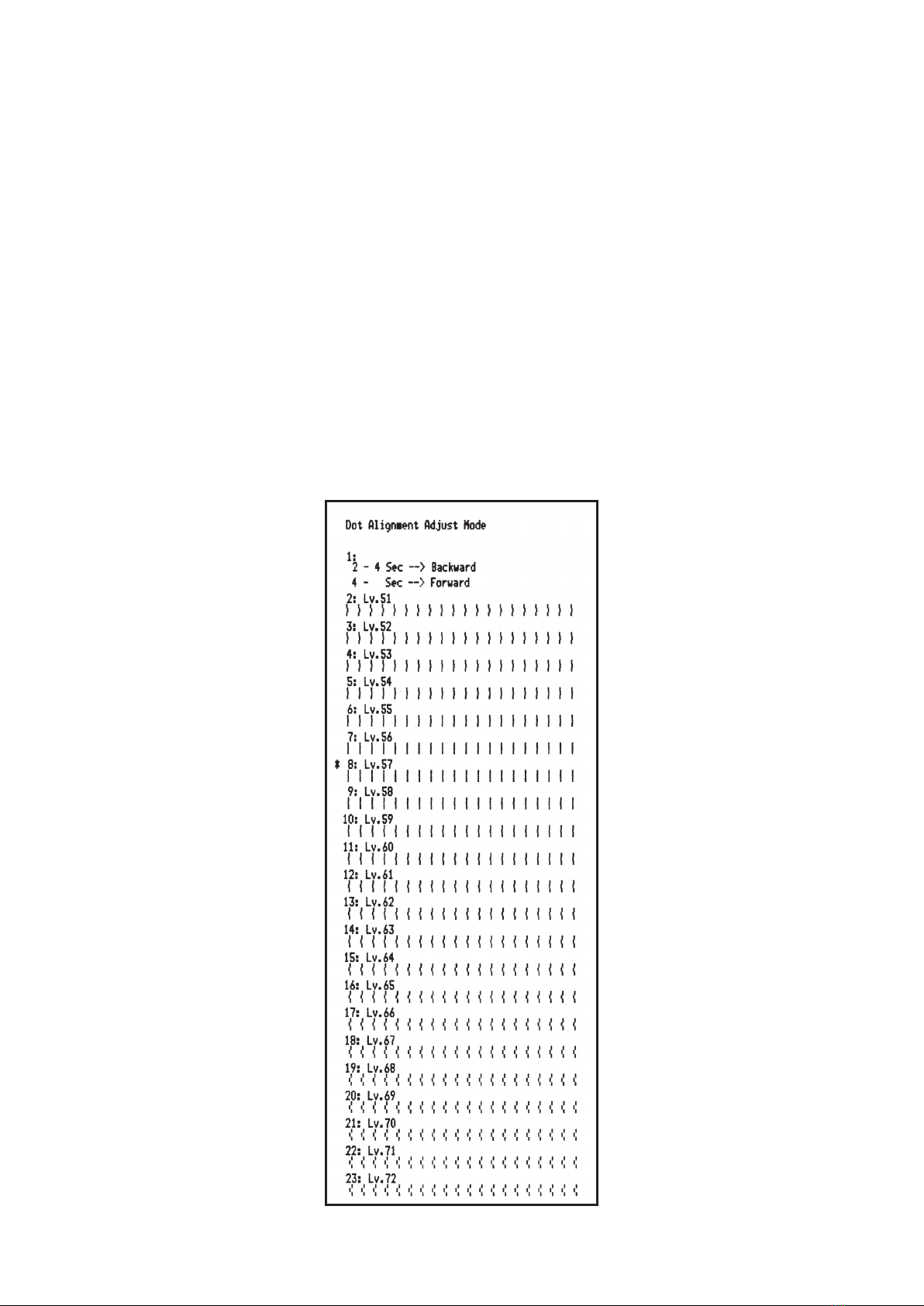
To adjust, select the adjustment pattern with the smallest amount of discrepancy in the dots in coming and going
directions by looking at the print results. To do so, count from the top line to the line of the desired pattern,
and press the FEED switch for that number of times. When doing so, when you get to the number of times that
corresponds to the desired line number, continue to press the FEED switch (approximately 2 seconds) until the
buzzer rings for a long time to set the new value.
< For example, to set the eighth line from the top, press the FEED switch seven times, and on the eighth time,
hold down the FEED switch (for approx. 2 seconds) until the switch buzzer rings. >
If you press the FEED switch up to 23 times, which is the switch setting range, the buzzer will ring once. If you
go beyond that the buzzer will issue a warning by repeatedly ringing.
If you do not see a pattern in the adjustment patterns that you can use, you can use the Backward or Forward
operations below to change the settings of the dot correction and reprint the pattern, then retry the operations
from #3. above.
Backward:
Hold down the FEED switch for two to four seconds. e buzzer will ring and an adjustment pattern
corrected more to the le than the outward pass, and more to the right than return pass than the currently
printed pattern.
Forward:
Hold down the FEED switch for more than four seconds. e buzzer will ring twice and an adjustment
pattern corrected more to the right than the outward pass, and more to the le than return pass than the
currently printed pattern.
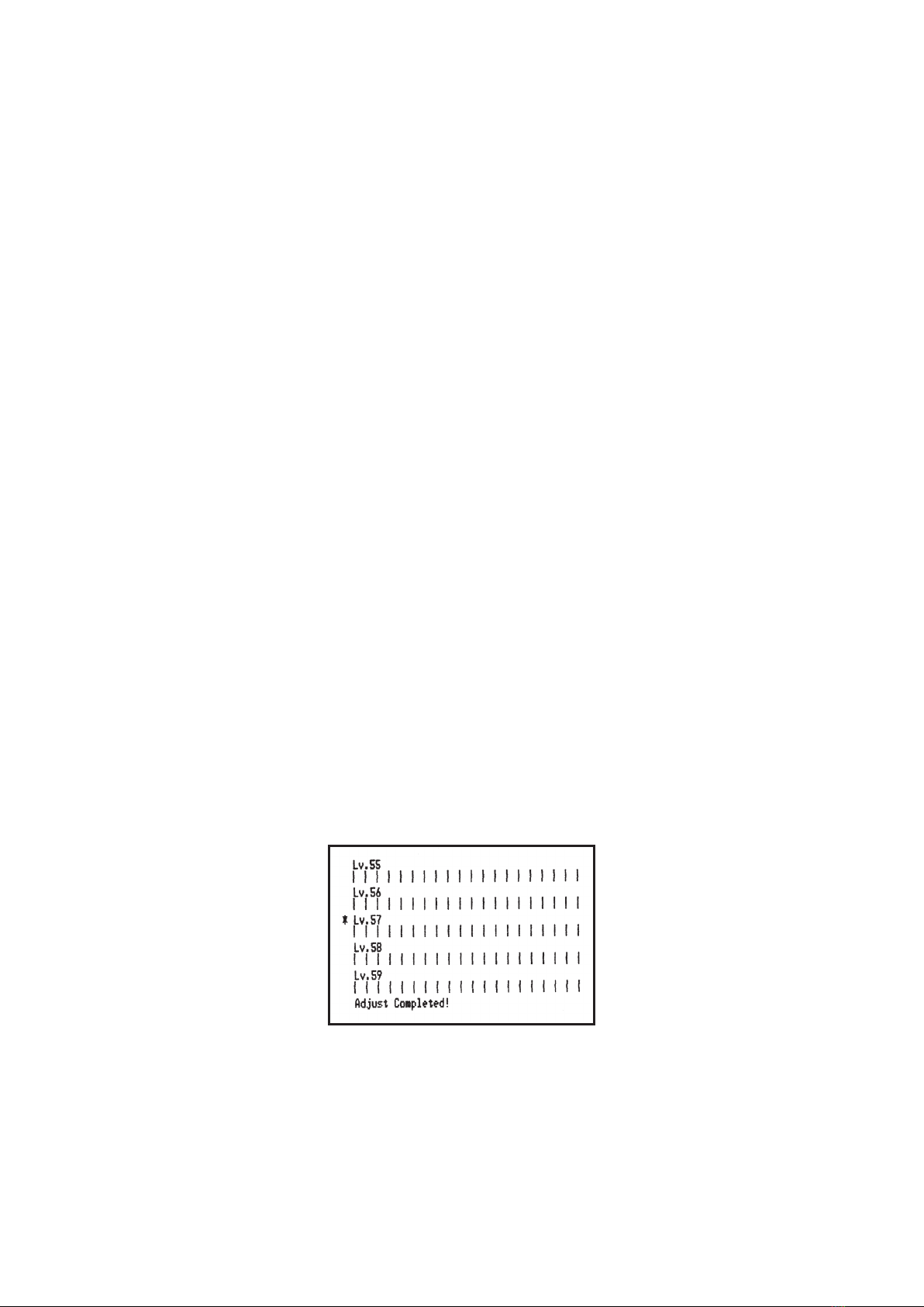
Aer making the setting, the printer will then write that new setting to the non-volatile memory.Below that, the
printer will print the set dot adjustment pattern and the message “Setting Completed.”
Note: e printer will write the setting to the non-volatile memory between the time the long buzzer has
rung when you have determined the setting and printing of the message has started. If you turn the
power o during that time, the dot adjustment setting and all memory switch settings will be initialized.
Absolutely do not turn the power o.
6.
7.
8.
e buzzer will ring once, for a long time, and the printer will automatically be reset.
is ends the printing position adjustment mode.
9.
- 7 -

5. Adjusting the Black Mark Sensor
Check that the printer power is o. Unplug the power cord from the outlet.
Turn the printer over as shown in the drawing (vertical layout) and remove the screw to remove the DIP switch
cover on the bottom of the printer. You will not be able to make the correct adjustments if the printer is turned
on its side. Always set the printer as shown in the drawing (the vertical layout).
1.
2.
e volume <VR2> is turned to make the adjustments, so check the position of the volume. Have a small,
regular screwdriver ready to insert into the hole.
Set ordinary roll paper that is not for black marks.
Plug in the power cord, and turn the printer on while pressing the FEED switch.
Aer the buzzer beeps four times, release the FEED switch.
e printer will enter the black mark sensor adjustment mode.
Use the regular screwdriver to turn the volume <VR2>. Adjust this to the position where both the ERROR lamp
(red) and the POWER lamp (green) both light.
Turn the power switch o.
is ends the black mark sensor adjustment.
3.
4.
5.
6.
7.
8.
81
Power OFF
VR2
VR1
- 8 -

CHAPTER 2
PARTS REPLACEMENT
is chapter explains disassembly and reassembly of the printer. Note the following precautions during
disassembly and reassembly.
1. Disconnect the printer power cord plug from the wall outlet before servicing it.
2. Assembly is the reverse of disassembly unless otherwise specied.
3. Aer reassembly, coat the screw heads with locking sealant.
4. Lubrication information is not provided in this chapter. Refer to item 2 of chapter 3.
1.RearCoverUnit.................................................10
2.FrontCoverandCaseUnit.......................................10
3.TearBar........................................................12
4.RibbonBase ...................................................12
5.PrinterMechanism .............................................13
6.PrintHead .....................................................13
7.PlatenArmUnit ................................................14
8.CRMotor.......................................................14
9.PFMoter.......................................................15
10.PowerUnit....................................................15
11.MainLogicBoard..............................................16
2

1
2
3
3
4
1. Rear Cover Unit
Turn the power switch 1o and unplug the power
plug from the AC outlet.
Pull the open lever 2toward yourself to open the
rear cover.
Removal
• 4 screws 3
• Rear cover unit 4
1.
2.
3.
2. Front Cover and Case Unit
Turn the power o and unplug the power plug from
the AC outlet.
Open the front cover 1.
Removal
• 3 screws 2
ere is a little play in the printer mechanism by rst
removing the screws fastening the case unit. is will
make it easier to remove the front cover 1.
• Front cover 1
Remove the front cover with the procedures below.
(1) Widen the A portion on the right side of the front
cover 1to remove from the front cover from the
mechanism.
(2) Li the right side removed from the mechanism.
1.
2.
3.
A
1
22
- 10 -

(3) With the same procedure on the other side of the
front cover 1, remove by widening the A portion.
• Open lever 3
• Case unit 4
At this time, widen the case that is near
the power switch and avoid touching the
switch. is can be easily removed by li
the backside at an angle.
3
4
- 11 -

3. Tear Bar
Turn the power o and unplug the power plug from
the AC outlet.
With the procedures of 2, remove the case unit.
Removal
• 2 screws 1
• Tear bar 2
1.
2.
3.
4. Ribbon Base
Turn the power o and unplug the power plug from
the AC outlet.
With the procedures of 2, remove the case unit.
Removal
• Stop ring 1
• Spring 2
• Ribbon base 3
1.
2.
3.
1
2
1
2
3
- 12 -

5. Printer Mechanism
Turn the power o and unplug the power plug from
the AC outlet.
With the procedures of 2, remove the case unit.
Removal
• 5 screws 1
• Connectors 2
• FL cable 3
• Printer mechanism 4
1.
2.
3.
6. Print Head
Turn the power o and unplug the power plug from
the AC outlet.
With the procedures of 5, remove the printer
mechanism.
Removal
• 2 screws 1
• Print head 2
1.
2.
3.
1
4
1
3
2
2
2
1
1
1
2
- 13 -

7. Platen Arm Unit
Turn the power o and unplug the power plug from
the AC outlet.
With the procedures of 5, remove the printer
mechanism.
Removal
• Four stop rings 1
• Spring 2
• Platen arm sha 3
• Platen arm unit 4
1.
2.
3.
8. CR Motor
Turn the power o and unplug the power plug from
the AC outlet.
With the procedures of 5, remove the printer
mechanism.
Removal
• 2 screws 1
• CR motor 2
1.
2.
3.
1
2
1
1
2
11
3
4
- 14 -

1
1
3
4
55
6
2
5
1
9. PF Moter
Turn the power o and unplug the power plug from
the AC outlet.
With the procedures of 5, remove the printer
mechanism.
Removal
• 3 screws 1
• Paper guide A 2
• 5 screws 3
• Fastener 4
• Main chassis 5
• Screw 6�
• Paper feed gear cover 7�
• Screw 8
• PF motor 9
1.
2.
3.
10. Power Unit
Turn the power o and unplug the power plug from
the AC outlet.
With the procedures of 5, remove the printer
mechanism.
Removal
• 3 screws 1
• Connector 2�
• Screw 3
• 2 screws 4�
• 4 screws 5
• Power Unit 6
1.
2.
3.
83
3
121
9
3
6
7
3
5
4
- 15 -

1
1
12
11. Main Logic Board
Turn the power o and unplug the power plug from
the AC outlet.
With the procedures of 9, remove the power unit.
Removal
• 4 screws 1
• Main logic board 2
1.
2.
3.
- 16 -

CHAPTER 3
MAINTENANCE AND LUBRICATION
3
1.Maintenance................................................ 18
1-1.Cleaning...................................................18
1-2.Checks.....................................................18
2.Lubrication ................................................. 19
2-1.Lubricant ..................................................19
2-2.LubricatingMethod.........................................19
2-3.LubricatedAreas ...........................................19
3.ScrewLocking............................................... 20
Other manuals for SP700 Series
2
Table of contents
Other Star Printer manuals

Star
Star TSP847II User manual

Star
Star SP742 Series User manual

Star
Star TSP100III Series User manual

Star
Star SP200F SERIES User manual

Star
Star LC-7211 User manual

Star
Star TSP847IIU-24 User manual

Star
Star SP712 Series User manual

Star
Star Star NX-500 User manual

Star
Star TSP654II Series User manual

Star
Star Dot Impact Printer User manual

Star
Star Star NX-2430 User manual

Star
Star SM-S220I SERIES User manual

Star
Star futurePRNT TSP100IIU Manual

Star
Star HSP7000 User manual

Star
Star SM-T300 Use and care manual

Star
Star HSP7000 User manual

Star
Star SM-S400 Quick start guide

Star
Star mC-Label3 Quick start guide

Star
Star SP200F SERIES User manual

Star
Star NX-1001 User manual