Star TSP654II Series User manual

THERMAL PRINTER
TSP650II SERIES
Hardware Manual

Federal Communications Commission
Radio Frequency Interference
Statement
is device complies with Part 15 of FCC Rules and Industry Canada licence-exempt RSS standard(s). Operation is
subject to the following two conditions:
(1) is device may not cause harmful interference, and
(2) this device must accept any interference received, including interference that may cause undesired operation.
Le présent appareil est conforme aux CNR d'Industrie Canada applicables aux appareils radio exempts de licence.
L'exploitation est autorisée aux deux conditions suivantes :
(1) l'appareil ne doit pas produire de brouillage, et
(2) l'utilisateur de l'appareil doit accepter tout brouillage radioélectrique subi, même si le brouillage est susceptible
d'en compromettre le fonctionnement.
FCC CAUTION
Changes or modications not expressly approved by the party responsible for compliance could void the user’s
authority to operate the equipment.
For compliance with the Federal Noise Interference Standard, this equipment requires a shielded cable.
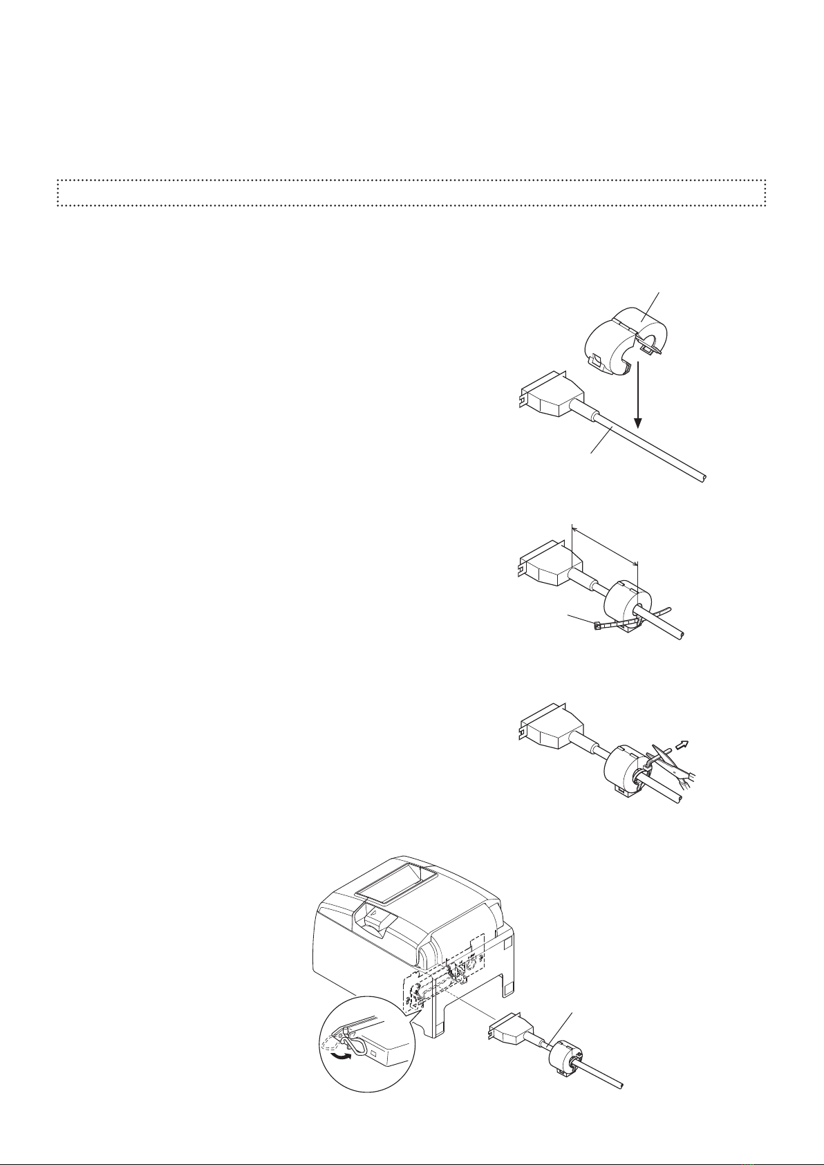
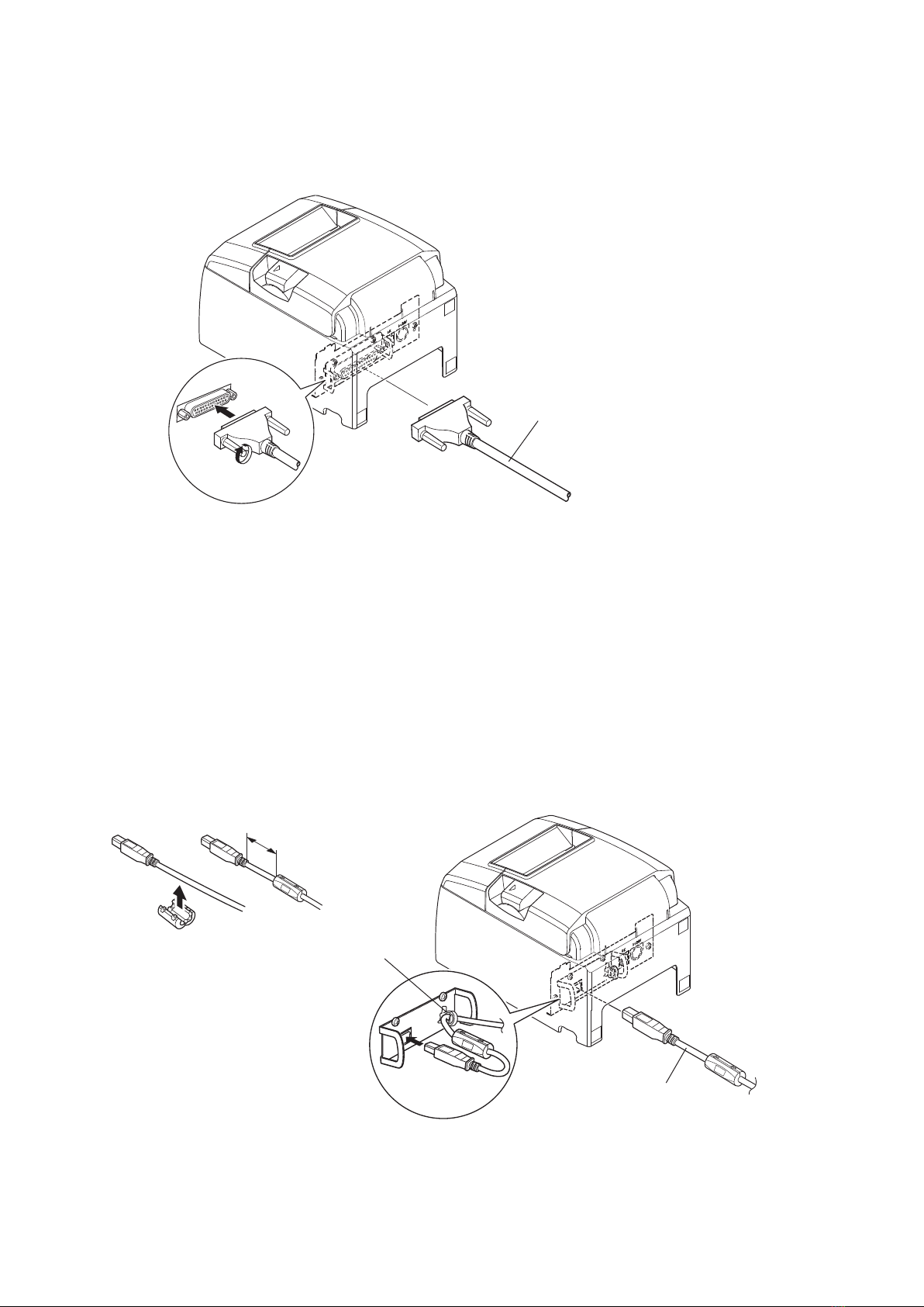
For RF interference suppression, if a ferrite core is provided with this device, ax it to the interface cable.
NOTE:
is equipment has been tested and found to comply with the limits for a Class A digital device, pursuant to Part
15 of the FCC Rules. ese limits are designed to provide reasonable protection against harmful interference when
the equipment is operated in a commercial environment. is equipment generates, uses and can radiate radio
frequency energy and, if not installed and used in accordance with the instruction manual, may cause harmful
interference to radio communications. Operation of this equipment in a residential area is likely to cause harmful
interference in which case the user will be required to correct the interference at his own expense.
CAN ICES-3 (A) / NMB-3 (A)
is equipment complies with FCC/IC radiation exposure limits set forth for an uncontrolled environment and
meets the FCC radio frequency (RF) Exposure Guidelines in Supplement C to OET65 and RSS-102 of the IC radio
frequency (RF) Exposure rules. is equipment has very low levels of RF energy that it deemed to comply without
maximum permissive exposure evaluation(MPE). But it is desirable that it should be installed and operated keeping
the radiator at least 20cm or more away from person's body (excluding extremities: hands,wrists,feet and ankles).
Cet équipement est conforme aux limites d"exposition aux rayonnements énoncées pour un environnement non
contrôlé et respecte les règles les radioélectriques (RF) de la FCC lignes directrices d'exposition dans le Supplément
C à OET65 et d"exposition aux fréquences radioélectriques (RF) CNR-102 de l"IC. Cet équipement émet une
énergie RF très faible qui est considérée conforme sans évaluation de l"exposition maximale autorisée. Cependant,
cet équipement doit être installé et utilisé en gardant une distance de 20 cm ou plus entre le dispositif rayonnant et
le corps (à l"exception des extrémités : mains, poignets, pieds et chevilles).

國家通訊傳播委員會
國家通訊傳播委員會國家通訊傳播委員會
國家通訊傳播委員會(NCC)
(NCC)(NCC)
(NCC)警告
警告警告
警告
根據「低功率電波輻射性電機管理辦法」第十條
製造、輸入或販賣低功率射頻電機者,應於低功率射頻電機使用說明書內加
印第十二條及第十四條之規定內容。
「低功率電波輻射性電機管理辦法」第十二條
經型式認證合格之低功率射頻電機,非經許可,公司、商號或使用者均不得
擅自變更頻率、加大功率或變更原設計之特性及功能。
「低功率電波輻射性電機管理辦法」第十四條
低功率射頻電機之使用不得影響飛航安全及干擾合法通信;經發現有干擾現
象時,應立即停用,並改善至無干擾時方得繼續使用。
前項合法通信,指依電信法規定作業之無線電通信。
低功率射頻電機須忍受合法通信或工業、科學及醫療用電波輻射性電機設備
之干擾。

Trademark acknowledgments
TSP650II : Star Micronics Co., Ltd.
Notice
•All rights reserved. Reproduction of any part of this manual in any form whatsoever, without STAR’s express
permission is forbidden.
•e contents of this manual are subject to change without notice.
•All eorts have been made to ensure the accuracy of the contents of this manual at the time of going to press.
However, should any errors be detected, STAR would greatly appreciate being informed of them.
•e above notwithstanding, STAR can assume no responsibility for any errors in this manual.
•IOS is a trademark or registered trademark of Cisco in the U.S. and other countries and is used under license.
•Android is a trademark of Google Inc.
•Windows is registered trademarks of Microso Corporation.
•Bluetooth® wordmark and logo are registered trademarks owned by Bluetooth SIG, Inc.
Copyright
©
2013-2017 Star Micronics Co., Ltd..
Caution Symbol
ese symbols are located near the thermal print head.
Because the thermal print head is hot immediately aer printing, do not touch it. Static
electricity can damage the thermal print head. To protect the thermal print head from
static electricity, do not touch it.
is symbol is located near the cutter.
Never touch the cutter blade, as you could injure your ngers.
is symbol is located near the peripheral drive connector.
Do not connect this to a telephone.
is symbol is located near the screws securing the case or the protective plate, which
should not be opened by individuals other than service personnel. Individuals, other
than service personnel, should not remove these screws. High voltage areas in the case
can be dangerous.

TABLE OF CONTENTS
1. Unpacking and Installation......................................................................... 1
1-1. Unpacking .................................................................................................... 1
1-2. Notes about Installation ............................................................................... 1
2. Parts Identication and Nomenclature....................................................... 2
3. Setup ............................................................................................................ 3
3-1. Connecting the Interface Cable to the PC...................................................... 3
3-2. Connecting the Interface Cable to the Printer ���������������������������������������������� 4
3-3. Connecting the AC Adapter .......................................................................... 7
3-4. Turning the Power On................................................................................... 8
3-5. Connecting to a Peripheral Device ................................................................ 8
3-6. Loading a Paper Roll..................................................................................... 9
3-7. Bluetooth Settings (For Bluetooth Interface Models only)............................... 12
3-8. Setup Precautions ....................................................................................... 17
4. Attaching the Accessories........................................................................... 19
4-1. Attaching the Holder Plate.......................................................................... 19
4-2. Attaching the Rubber Feet .......................................................................... 21
4-3. Switch Cover Installation............................................................................ 21
5. Adjusting the Near-end Sensor .................................................................. 22
6. Error Indicators ......................................................................................... 23
6-1. Recoverable errors ...................................................................................... 23
6-2. Unrecoverable errors .................................................................................. 23
7. Preventing and Removing Paper Jams...................................................... 24
7-1. Preventing Paper Jams ................................................................................ 24
7-2. Removing Paper Jams ................................................................................. 24
7-3. Releasing the Cutter Lock ........................................................................... 25
8. Maintenance ............................................................................................... 26
8-1. Thermal Head............................................................................................. 26
8-2. Platen Rubber Roller .................................................................................. 26
8-3. Paper Holder .............................................................................................. 26

-
1
-
1. Unpacking and Installation
* Accessories vary depending on the model and the
region where the printer was purchased.
Paper roll
Printer
Holding plate
Screws
Switch blind
Safety Instruction
&
Setup sheet
Paper roll guide
Rubber feet
1-1. Unpacking
Aer unpacking the unit, check that all the necessary accessories are included in the package.
1-2. Notes about Installation
1. Choose a rm, level surface where the printer will not be exposed to vibration.
2. Make sure that the printer is connected to a reliable power outlet. It should not be on the same electric circuit as copi-
ers, refrigerators, or other appliances that cause power spikes.
3. e power outlet you plan to connect to for power should be nearby and unobstructed.
4. Make sure that the printer is not exposed to direct sunlight.
5. Make sure that the printer is well away from heaters and other sources of extreme heat.
6. Do not locate the printer in a badly ventilated or dusty environment.
7. Make sure that the room where you are using the printer is not too humid.
8. is device employs a DC motor and switches that have an electrical contact point.
Avoid using the device in environments where silicon gas can become volatile.
9. Use the printer within the boundaries indicated in the environmental requirements. Even when the ambient tem-
perature and humidity are within the specications, avoid radical changes in environmental conditions. e suitable
operating temperature range is as follows:
Operating temperature: 5°C to 45°C
10. When disposing of the printer, obey local regulations.

-
2
-
ERROR
FEED
POWER
TSP650
2. Parts Identication and Nomenclature
Control panel
Features lamps that indicate printer
status and a button for operating
the printer.
Printer cover
Open to replace paper.
Do not open while printing.
Power switch
Turnstheprinteron
and o.
Connects to peripheral devices
such as cash drawers.
Do not connect this to a tel-
ephone line.
Peripheral drive connector
Connects to an optional
AC adapter.
Power inlet
Connects to a host PC
through a cable.
Interface connector
Lights when the printer is online.
This lamp also indicates errors, in
combination with other lamps.
POWER lamp (green)
Lights when the cover is open.
This lamp also indicates errors, in
combination with other lamps.
ERROR lamp (red)
When the printer is online, pressing
this button feeds the paper roll.
FEED button
Cover open lever
Use this lever to open the
printer cover.

-
3
-
3. Setup
3-1. Connecting the Interface Cable to the PC
3-1-1. Parallel Cable
Connect the parallel cable to a parallel port on your PC.
3-1-2. RS-232C Cable
Connect the RS-232C cable to a RS-232C port on your PC.
3-1-3. USB Cable
Connect the USB cable to a USB port on your PC.
3-1-4. Ethernet Cable
Connect the Ethernet cable to a USB port on your PC.

-
4
-
Parallel interface cable
Ferrite core
Interface cable
5 cm
(maximum)
Fastener
Pull and cut
3-2. Connecting the Interface Cable to the Printer
Printer cables are not included in the package.
Obtain an appropriate cable that complies with the specications beforehand.
Because the appropriate interface cable diers depending on the system that you are connecting the printer to, contact
the dealer that you bought the product from if you are unsure about what cable to use.
Before connecting or disconnecting an interface cable, be sure to disconnect the AC adapter’s power cord from the outlet.
3-2-1. Parallel Interface Cable
To connect a parallel cable, follow the procedure given below.
(1) Make sure the printer is turn o.
(2) Ax the ferrite core onto the cable as shown in the illustration.
(3) Pass the fastener through the ferrite core.
(4) Loop the fastener around the cable and lock it. Use scissors to cut
o any excess.
(5) Connect the interface cable to the connector on the rear panel of
the printer.
(6) Fasten the connector clasps.

-
5
-
RS-232C interface cable
USB cable
Cable hook
4 cm (maximum)
3-2-2. RS-232C Interface Cable
(1) Make sure that the AC adapter’s power cord is not connected to the outlet.
(2) Connect the interface cable to the connector on the rear panel of the printer.
(3) Tighten the connector screws.
3-2-3. USB Cable
To connect a USB cable, follow the procedure given below.
(1) Make sure that the AC adapter’s power cord is not connected to the outlet.
(2) Connect the USB cable to the USB port.
(3) As shown in the gure, pass the cable through the cable hooks to hold it in place.

-
6
-
Ethernet cable
IFBD-HE07
3-2-4. Ethernet Cable
To connect the cable, follow the procedure given below.
(1) Make sure that the AC adapter’s power cord is not connected to the outlet.
(2) Connect the Ethernet cable to the Ethernet port.
g Link disconnection detection feature
e Ethernet interface model is equipped with a link disconnection detection feature.
If the printer is turned on when an Ethernet cable is not connected to it, the POWER and ERROR lamps are simul-
taneously turned on and o at 4-second intervals to indicate the disconnection.
Be sure to connect the Ethernet cable from a PC or hub to the printer, and then turn the printer on.

-
7
-
3-3. Connecting the AC Adapter
Note: Before connecting or disconnecting the AC adapter, make sure that the printer and all the devices connected
to it are turned o.
en remove the power cord from the outlet.
(1) Connect the AC adapter to the power cord.
(2) Connect the AC adapter to the connector on the printer.
(3) Insert the power cable plug into an AC outlet.
CAUTION
When disconnecting the cable, take hold of the cable
connector to pull it out. Releasing the lock makes it easy
to disconnect the connector.
Pulling the cable excessively could cause damage to the
connector.
Note: We recommend that you use the standard AC adapter and power cord.
If you are not using the optional AC adapter (PS60A-24B1 series) and are instead preparing your own power
supply, note the following points.
• Use a power supply that is 24 VDC ± 10% and 2.1 A or more.
(Select a power supply with current capacity that is appropriate for the actual printing ratio.)
• Use a power supply that supports with SELV output or LPS (Limited Power Source).
• Take into consideration the noise in the environment that the printer is installed in, and take appropri-
ate measures to protect the printer from static electricity, AC line noise, etc.

-
8
-
Power switch
3-4. Turning the Power On
Connect the power cord according to the procedure in section 3-3, “Connecting the AC Adapter”.
Turn on the power switch, which is on the le side of the printer.
e POWER lamp on the control panel will light.
3-5. Connecting to a Peripheral Device
You can connect a peripheral device to the printer using a modular plug.
Follow the procedure given below.
1) Make sure that the AC adapter’s power cord is not connected to the outlet.
2) Connect the modular jack plug to the peripheral drive connector on the rear panel of the printer.
Connect the other end of the cable to the modular jack of the peripheral device.
CAUTION: Do not connect a telephone line to the peripheral drive connector. Doing so may cause the printer
to malfunction. Also, for safety purposes, do not connect a wire that may carry excessive voltage to
the peripheral drive connector.

-
9
-
Cover open lever
Paper roll
3-6. Loading a Paper Roll
Use a paper roll that complies with the printer specications.
(1) Push the cover open lever, and open the printer cover.
(2) Load the paper roll into the printer in the direction indicated by the gure, and pull the leading edge of the paper
straight toward you.
(3) Push on both sides of the rear cover to close it.
Note 1: Be careful not to pull the paper out at an angle, because doing so may cause the paper to jam or skew.
2: Be sure not to close the printer cover by pushing only one side.
3: Be careful not to get your ngers caught when opening or closing the printer cover.
4: Aer the printer cover is closed, the printer performs initial operations (from paper feeding to paper
cutting). Do not open the printer cover until the initial operations are complete.

-
10
-
3-6-1. Compliant Paper Roll Specications
Paper thickness 53 μm to 85 μm
Paper width
79.5
± 0.5
mm
57.5 ± 0.5 mm
External dimensions
• Roll diameter Max. f83 mm
• Take up paper roll width 80 +0.5
mm
/
58
+0.5
mm
Core inner and outer diameters Inner diameter f12 ± 1 mm, external diameter f18 ± 1 mm
Printed surface Outer edge of roll
Note 1: Do not glue or tape the paper roll and sha core together.
2: Do not fold the tail end of the paper.
3: For details on recommended thermal paper, see the following webpage.
http://www.starmicronics.com/support/
- 1- 1

-
11
-
Paper roll guide
A
3-6-2. Changing the Paper Width
When using 57.5 mm width paper rolls, attach the supplied paper roll guide to the printer. When you change the eective
print width (paper roll width), change the printer utility’s memory switch setting.
For details, see the printer utility help.
(1) Insert the paper roll guide rmly into the slot in the printer labeled "r58" as shown in the gure below.
(2) Secure the paper roll guide in place by pushing the section marked as “A” in the gure.
Note1 : Do not insert the paper roll guide into the slot labeled "r65".
It may cause problems.
2: Do not change the paper width while the printer is in use.
e amount of wear on the thermal head, rubber roller, and cutter varies depending on the paper width.
is varying amount of wear may cause problems in printing and cutting.

-
12
-
PAIR
RST
PAIR
RST
PAIRRST
PAIR button
PAIR buttonRST button
LED
< iOS > < Android >
Flashing green LED
3-7. Bluetooth Settings (For Bluetooth Interface Models only)
(2) Aer turning the printer's power switch on, press and hold the PAIR button on the rear interface of the printer for 5
seconds or more, and then release it. e LED will ash green.
Pair the printer with the master device by following the procedure below.
Compatibility list: http://www.star-m.jp/prjump/000031.html
3-7-1. Pairing using SSP (Simple Secure Pairing) [Default]
(1) Working on the master device, tap [Settings] and set [Bluetooth] to ON.
<
LED
>
Indicates the status of the Bluetooth interface.
Green (on): Not connected.
Green (ashing): Ready to start pairing.
Blue (on): Connected.
Purple (ashing): Auto connection ON.
(3) Pairing will be possible for 60 seconds from when the LED begins ashing green. During this time, execute "Search
for devices" from the master device and tap the relevant device from the displayed list.
Device name: Star Micronics (default)
(4) In an iOS device, aer pairing, the LED will automatically begin ashing blue, and the printer will be automatically
connected. In an Android device, the LED turns blue only while data is sent.
(5) Connect to the printer from the master device application and perform printing. If the printing is successful, the
pairing process has been completed.

-
13
-
ERROR
FEED
POWER
TSP650
Note: e printer performs various processes immediately aer connecting to or disconnecting from a master
device.
Please wait approximately 0.1 seconds aer connecting, and approximately 0.5 seconds aer disconnecting,
before beginning communications with the printer.
3-7-2. Pairing using PIN code
Enter the following information in the master device if it does not support SSP, or when otherwise necessary.
PIN: 1234 (default)
Device name: Star Micronics (default)
It is recommended that you change the PIN code for greater security.
For details regard changing the PIN code, please see the “Soware Manual -Star Bluetooth Utility- ”.
3-7-3. Auto Connection Function (iOS only)
Each time the wireless connection is disconnected while communicating with upper-level iOS devices including iPad over
Bluetooth, it is necessary to move back to the Bluetooth setting screen in the upper-level iOS device and tap the desired
printer name again to build a connection. is is an iOS specication.
In order to save this labor, this printer is equipped with the Auto Connection function that automatically requests a con-
nection from an upper-level iOS device that was connected to the printer last time.
e default setting of this function may dier according to the printer model you are using.
Conrm the default settings for your printer, as well as the use examples for ON/OFF settings, and then make the settings
to match your purpose.
You can also check the current ON/OFF setting by performing self-printing.
< Conrmation procedure by self-printing >
(1) While the printer cover is closed, hold down the FEED button on the
operation panel, and then turn on the power switch.
(2) Self-printing starts and the settings for F/W version, DIP switch,
memory switch, and so on are printed.
Subsequently the interface information is printed and nally the
current ON/OFF settings are printed.
Note: If "Auto Connection function" is set to ON when using devices other than iOS, a Bluetooth communi-
cation with the printer may fail. To use devices other than iOS, such as the Android/Windows devices,
make sure you turn o the "Auto Connection" function before using the printer.
For information on how to set up this function, see "3-7-4. Setting up Auto Connection".

-
14
-
Auto Connection ON Auto Connection OFF
Reconnecting without changing
the master device
After the printer is turned on, it
automatically connects to the last
master device that was connected.
After turning on the printer, tap
this printer's name on the Blue-
tooth settings screen on the mas-
ter device.
Changing the connected master
device
Disconnect the Bluetooth connec-
tion in such a way as to turn OFF
the power to the upper-level de-
vice automatically connected.
Then, establish a pairing with a
desired master device.
After turning on the printer, es-
tablish a pairing with a desired
master device.
Example (recommended) When connecting directly to the
printer from one master device.
When using the printer with mul-
tiple master device.
See the table below for details of Auto Connection setting.

-
15
-
< Current Setting >
Auto Connection : OFF
To enable this setting, turn
Printer Power OFF and turn ON.
PAIR
RST
PAIR
RST
RST button
3-7-4. Setting up Auto Connection
uSetting up from the Main Unit for the TSP650II
Note : e following procedure explains how to change the Auto Connection function setting from ON to OFF.
If you want to change it from OFF to ON, please follow the same procedure.
(1) When paper is loaded in the printer and it is turned on, the [POWER] LED(green) on the front of the printer
turns on.
(2) If you hold down the [RST] button on the back of the printer for at more than ve seconds, initial operations are
performed in the same way as when the power is turned on, and the LEDs on the front of the printer ash. If you
press the [RST] button when the printer is placed upright, place it horizontally again while the LED is ashing.
(3) The following information is printed. After that, turn the printer off and then back on again to set "Auto Con-
nection" to OFF.
(4) To make sure "Auto Connection" is set to OFF correctly, perform self-printing as described in "3-7-3. Conrmation
procedure by self-printing”.
Note : Only Bluetooth Firmware Version 2.0 or later allows you to switch ON/OFF by pushing the [RST] button.
e Bluetooth Firmware version can be conrmed by self-printing. (For more information, see "3-7-3.
Conrmation procedure by self-printing”.)
uSetting from the Software
Aerpairingyourdeviceandthe TSP650II,change"AutoConnection"in thefollowingapplicationprovided byourcompany.
liOS: Download "Star Setting Utility" from the following Web site.
http://www.star-m.jp/prjump/000003.html
lAndroid: Download "Star Setting Utility" from the following Web site.
http://www.star-m.jp/prjump/000004.html
lWindows: Download "Star Bluetooth Utility" from the following Web site.
http://www.star-m.jp/prjump/000006.html
Table of contents
Other Star Printer manuals

Star
Star TSP650II series User manual

Star
Star SM-S220I SERIES User manual

Star
Star SM-T300 Use and care manual

Star
Star Dot Impact Printer User manual

Star
Star NX-1001 User manual

Star
Star SP6000 SERIES User manual

Star
Star SM-S201 User manual

Star
Star TSP100LAN User manual

Star
Star StarPRNT mC-Print3 Series User manual

Star
Star WinType 800C User manual

Star
Star TSP847IIU-24 User manual

Star
Star Multi-Font XR-1020 User manual

Star
Star SM-L300 Series User manual

Star
Star Star NX-2430 User manual

Star
Star TSP100 futurePRNT Guide

Star
Star TUP500 Quick setup guide

Star
Star SM-T300 User manual

Star
Star Gemini-10X User manual

Star
Star TSP400 SERIES User manual

Star
Star SP712R series User manual