StarDental NuTorque Lite User manual
OM-EZ505E
Classification of Devices
Type of protection against electric shock :
- Class II equipment :
Degree of protection against electric shock :
- Type B applied part :
Method of sterilization or disinfection recommended by the manufacture :
- Refer to 7. Sterilization
Degree of safety of application in the presence of a flammable anesthetic mixture with air or with oxygen or
nitrousoxide :
- EQUIPMENT not suitable for use in the presence of a flammable anaesthetic mixture with air or with oxygen or
nitrous oxide.
Mode of operation :
- Continuous operation
Classification Degree and severity of danger or damage
WARNING Explains an instruction where personal injury or physical damage may occur.
CAUTION Explains an instruction where minor to medium injury or physical damage may occur.
NOTICE Explains an instruction that should be observed for safety reasons.
Read this manual thoroughly before use and operate the device properly.
These instructions will show you how to operate the product safety and prevent danger to you or others. They are
classified by the degree and/or severity of danger. All contents relating to safety should be oberserved.
Cautions for handling and operation
Please Read this operation manual carefully before use and keep for future reference.
OPERATION MANUAL
Thank you for purchasing the NuTorque®Lite. Read this Operation Manual carefully before use for operation instructions and care and
maintenance guidelines. Keep this Operation Manual for future reference.
Application
This motor is used for cutting / polishing of the tooth.
User
Dentist and dental assistant.
Prohibition
This motor is dental treatment use only. Do not use for Oral Surgical treatment.
CAUTION: Federal law restricts this device to sale by or on the order of a dentist.
Electric Handpiece System

CAUTION
NOTICE
· During vibration, the motor and the motor cord may affect computer and LAN cable. Noise could be heard during
operation near a radio receiver.
· Turn off the Power Switch after each use. If unit is to be stored for long periods of time, drain water from unit and hose.
· Responsibility for operating and maintaining Medical Devices belongs to the user.
· Store the system in the place where the temperature is at -10-60°C (14-140°F), humidity at 10-85%RH, atmospheric
pressure at 500-1060 hPa, and the system is not subject to air with dust, sulfur, or salinity.
· When trouble is found, contact your to dealer.
· Do not insert or remove power cord with wet hands, electric shock may occur.
· Be sure not to expose the unit to water. It may result in a short or electric shock.
· Do not use this device near combustibles, or in a place where explosion may occur.
· Do not disassemble, there are no user serviceable parts inside control unit.
· Do not hit / drop the unit or handpiece. Place unit in a stable place.
· Use the fuse of specified rating. [AC120V: T1.6A 250V (Ref No.FU100, FU101), AC230V: T800mA 250V (Ref No.
FU100, FU101)]
WARNING
· NuTorque®Lite system can be used with a hose connector that is manufactured in accordance with ISO 9168, type 2
or type 3.
· Connect to only 4-hole, 5-hole or 6-pin tubing.
· NuTorque Lite system is to be used by qualified personnel for dental treatment only, and only in a dental office.
· Patient safety must have first priority.
· Operate before use to check for vibration, noise, or overheating. If any abnormalities occur, stop using immediately
and contact your dealer.
· Grasp cord by plug to remove from outlet. DO NOT pull or yank on the cord itself.
· Do not connect / disconnect the handpiece during operation.
· Verify that the Speed Control Switch is adjusted within the allowable speed before use.
· When you install Control Box or Motor, DO NOT bend or twist the tubing or the cord. No unnatural force is needed to
do the installation.
· Never use the AC adapter for anything other than the control box of this product.
· Air Requirements: dry, free from contamination and oil. Use a compressor with a dry air system. Install an air filter if
necessary. Blow out the lines before installation.
· Do not Autoclave (or any other high temperature Sterilization) Control Box, AC Adapter, Motor Cord.
· The system functions normally in the environment where the temperature is at 0-40°C (32-104°F), humidity at 10-85%
RH, atmospheric pressure at 700-1060hPa, and no moisture condensation in the Control Unit. Use at outside of these
limits may cause malfunction.
· If the handpiece has not been used for a long period, check for noise, vibration, and overheating before use.
· The user shall be responsible for operation, maintenance and operation.
· NuTorque Lite needs special precautions regarding EMC and needs to be installed and put into service according to
the EMC information.
· Portable and mobile RF communications equipment can affect NuTorque Lite. Do not use RF equipment outskirts for
the product.
· The use of ACCESSORIES, transducers and cables other than those specified, with the replacement parts for internal
components,may result in increased EMISSIONS or decreased IMMUNITY of NuTorque Lite.
· NuTorque Lite should not be used adjacent to or stacked with other equipment.
. For safety, install the Control Unit in a place where the AC Adaptor can be easily removed. (It is possible to disconnect
the control unit from the power source by removing the AC Adaptor.)
. When installing the product, provide space of approximately 10cm around the Unit for easy access to the inlet and the
AC Adaptor.
. Be sure to use coolant air. Surface temperature will be more than 60°C if coolant air is not used.
2

2. Component Names
1. Specification
M o d e l 265316
Rated input AC28V 50/60 Hz
Drive Air Pressure 0.4MPa (4.0kgf/cm2=56.89psi)
or less
D i m e n s i o n s W127 x D149 x H66 mm
Control Box
M o d e l 265317
Rotation Speed 2,000 - 40,000 min-1 (rpm)
D i m e n s i o n s Ø22.5 x H81 mm
Cord Length Unshielded, App. 2.0m
Motor
Model 265290(120V) and 265291(230V)
Rated input AC120V 50/60Hz 41VA
AC230V 50/60Hz 41VA
Output AC28V 1.3A
Fuse
AC120V FU100 : T1.6A 250V
FU101 : T1.6A 250V
AC230V FU100 : T800mA 250V
FU101 : T800mA 250V
Dimensions W100 x D178 x H64 mm
Cord Length Unshielded, App. 5.0m
AC Adaptor
Handpiece Tubing ConnectorHandpiece Tubing Connector
Power SwitchPower SwitchPower Switch
AC Adapter Connector
AC Adapter Connector
Motor Cord Connector
Motor Cord Connector
3
Cord Length Unshielded, App. 2.0m
Power Cord

Fig.1
Fig.2
Fig.3
Fig.4
CAUTION
CAUTION
CAUTION
Handpiece Tubing
Connector
Nut
Handpiece Tubing
Motor Cord Connector
Motor Cord
Nut
AC Adapter Plug
AC Adapter Connector
3. Operating Control Box
· Only use 4/5 hole or 6 pin tubing.
· Do not use wet or contaminated air.
· Install an air filter if necessary. Blow out the lines before
installation.
(1)Connect the handpiece tubing from the delivery unit to the control box
Fit the handpiece tubing connector from the delivery unit to the
control box handpiece tubing connector and tighten. (Fig. 1)
(2)Connecting the Motor
Insert the Motor Cord Connector to the control box motor cord
connector and tighten. (Fig. 2)
(3)Connecting the AC adapter
Insert the AC adapter plug into the AC adapter connector before
plugging into wall outlet. (Fig. 3)
Never use the AC Adapter for anything other than the Control
Box of this product.
(4)Connecting the Power Cord
Insert the Power Cord into the Inlet of AC Adapter. (Fig. 4)
Plug cord into AC outlet.
· Be sure that there is no air or water coming from Handpiece Tubing when attaching to control box.
· Do not overtighten the handpiece tubing and motor cord nuts.
4
Motor Cord Connector
Handpiece Tubing
Connector
Nut
Handpiece Tubing
Motor Cord
Nut
AC Adapter Plug
AC Adapter Connector
Inlet
Power Cord
Inlet
Power Cord
AC AdapterAC Adapter
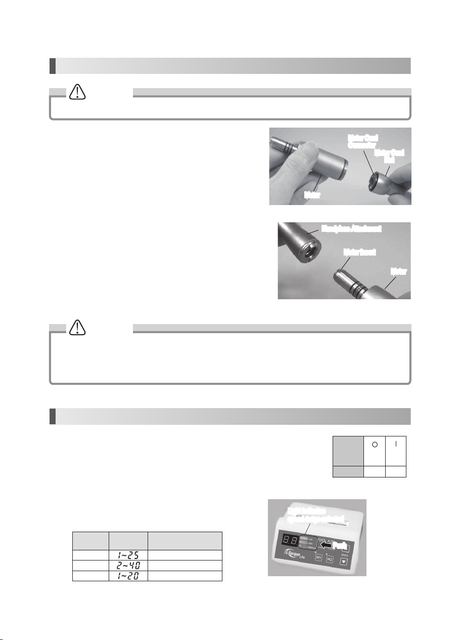
Fig.6
CAUTION
Fig.7
Motor
Motor Cord
Nut
Motor Cord
Connector
Handpiece Attachment
Motor Insert
Motor
CAUTION
(2)
Connecting/disconnecting the motor and the handpiece Attachments
Assemble the Handpiece Attachment by inserting the motor insert into
the E-Type Handpiece Attachment, and turn Attachment until it clicks
and positioning pins are aligned.
Remove the handpiece by pulling the handpiece attachment out from
the motor.
· Care should be taken when using any handpiece attachment which requires lubrication (E-Type Micromotor).
Following lubrication, stand the handpiece attachment vertically until the excess solution drains. Wipe the
handpiece then attach it to the micromotor.
· Do not connect or disconnect the handpiece until the motor has completely stopped.
5. Operation Section
(1)Insert the Power Cord Plug in AC outlet and turn on the Power Switch. When you turn on the
Power Switch, lamps and speed indicator will be illuminated.
(2)Before using this system, make sure to perform Foot Air Calibration function.
(Refer to 6. (1)Foot Air Calibration)
Power
Switch
Symbol
Mark
Function OFF ON
(3)Push the Gear Ratio Select Key to indicate the speed of the
attachment you will use. (Fig. 7)
Handpiece
Gear Ratio Indicator Speed (min-1(rpm))
16:1 100 - 2,500
1:1 2,000 - 40,000
1:5 10,000 - 200,000
Fig.5
4. Handling the Motor
(1)Connecting / disconnecting the motor and the motor cord
To remove the motor cord from the motor, unscrew and detach the
motor cord nut, and gently pull out the motor cord connector.
To connect, align and insert firmly the pins of the connector
carefully into the pin holes of the motor, and fasten the motor cord
nut securely (Fig. 5)
Push
Ensure that the motor has completely stopped before handling the motor.
5
Motor
Motor Cord
Nut
Motor Cord
Connector
Handpiece Attachment
Motor Insert
Motor
Light indicates
speed range selected
Light indicates
speed range selected
Push

Fig.9
A. Setting Lower Limit:
1)Press key and key at the same time for at least 3 seconds.
2)When alarm sounds, Speed Indicator will change to " " (Lower air pressure limit setting mode).
3)Press the key, Speed Indicator flashes " " and " ".
4)Press the Foot Pedal of the delivery unit, Speed Indicator shows the present air pressure. (Unit is kgf/cm2)
6. Convenient Functions
(5)Select FWD/REV rotation using the FWD/REV Select Key. (Fig. 9)
Lamp ON REV
Lamp OFF FWD
(6)The micromotor operation is controlled by the Air Switch/Foot
Pedal of the delivery unit.
(1)Foot Air Calibration
By using this function, you can to use the maximum speed, 40,000 min-1(rpm). You must set the upper and lower limit
of the air pressure to enable this function.
Perform this adjustment function after your purchase. Once it is adjusted, it will be memorized, and there is no need
to do this everytime.
NOTICE
· The displayed air pressure is only a guideline. Measure the correct air pressure with an air gage.
· The unit of displayed air pressure is "kgf/cm2". For other units, refer below.
ex)0.1kgf/cm2= 0.01MPa = 1.42psi
1.0kgf/cm2= 0.1MPa = 14.22psi
3.0kgf/cm2= 0.3MPa = 42.67psi
5)Press the Foot Pedal of the delivery unit, and hold the air pressure between " " - " ". Press key for at
least 3 seconds to save the lower limit of the air pressure.
Fig.8
(4)Set the maximum speed using the speed control switches. (Fig. 8)
NOTICE
Push
6
Speed UpSpeed Up
Speed DownSpeed Down
Set maximum SpeedSet maximum Speed
Lamp illumniated only during REV rotationLamp illuminated only during REV rotation
Push

4)Press the foot pedal of the delivery system, and hold the air pressure between " " - " ". Press key
until it beeps (more than 3 seconds)to memorize the upper limit of the air pressure.
NOTICE
· Default value is set to " " (kgf/cm2) = 0.3MPa = 42.67psi.
· When the air pressure is not between " " - " ", " " is displayed, and the setting will not be memorized.
5)Press both key and key at the same time until it beeps (more than 3 seconds).
When it beeps, the setting is complete. Set Speed Indicator by pressing key to " ".
The NuTorque®Lite is now ready to use at the maximum speed, 40,000 min-1(rpm).
(2)Light Brightness Adjusting Function
1)Press key and key at the same time until you hear a beep (more than 3 seconds).
2)When beep sounds, Indicator will change to " ". Press the key to change the Indicator to C3
( ) - Light Brightness adjustment mode. Press key to proceed to change to desired brightness.
3)Indicator will chang to " "(Default value), press key and adjust the brightness.
NOTICE
· Default value is set to " " Volt.
· Adjustable between " " - " ".
4)Press key until it beeps (more than 3 seconds) to set the brightness.
5)Press key and key at the same time for more than 3 seconds, once again. When it beeps,
this setting is complete.
(3)Program Function
It is possible to program two (2) presets (Speed, Gear Ratio, Forward/Reverse Direction)
Once set, you can choose between presets by pressing the or the key.
To set the values for Speed, Gear Ratio, Forward/Reverse Direction press key or key until it beeps (more than
3 seconds). When it beeps, this setting is complete.
NOTICE
· The displayed air pressure is only a guideline. Measure the correct air pressure with an air gage.
· The unit of displayed air pressure is "kgf/cm2". For other unit, refer to the NOTICE described in 4).
NOTICE
· Default value is set " " (kgf/cm2) = 0.05MPa = 7.11psi.
· When the air pressure is not between " " - " ", " " is displayed, and the setting will not be memorized
B. Setting Upper Limit:
1)After setting lower limit, press key. Speed Indicator will change to " " (Upper air pressure limit
setting mode).
2) Press the key, the Speed Indicator will flash " " and " ".
3)Press the Foot Pedal of the delivery system, the Speed Indicator displays the current air pressure. (Unit is kgf/cm2)
7

CAUTION
· Do not Autoclave (or any other high temperature Sterilization)Control Box, AC Adapter, Motor Cord.
· Do not lubricate the motor.
· Do not wipe or immerse the system in acidic water or acidic solutions.
· Do not sterilize with dirt on the surface. As this may cause rust.
7. Sterilization
Sterilize the Handpiece Attachments, Burs and Motor Only.
For the sterilization method, we recommend the autoclave sterilization
method.
Note: Attachments, burs and motor Must Be Cleaned and Sterilized
Before first use After Each Patient.
Sterilizing the Motor
1)Turn off the Power.
2)Detach the motor from the Motor Cord.
(Refer to 4. (1) Connecting / disconnecting the Motor and the Motor Cord)
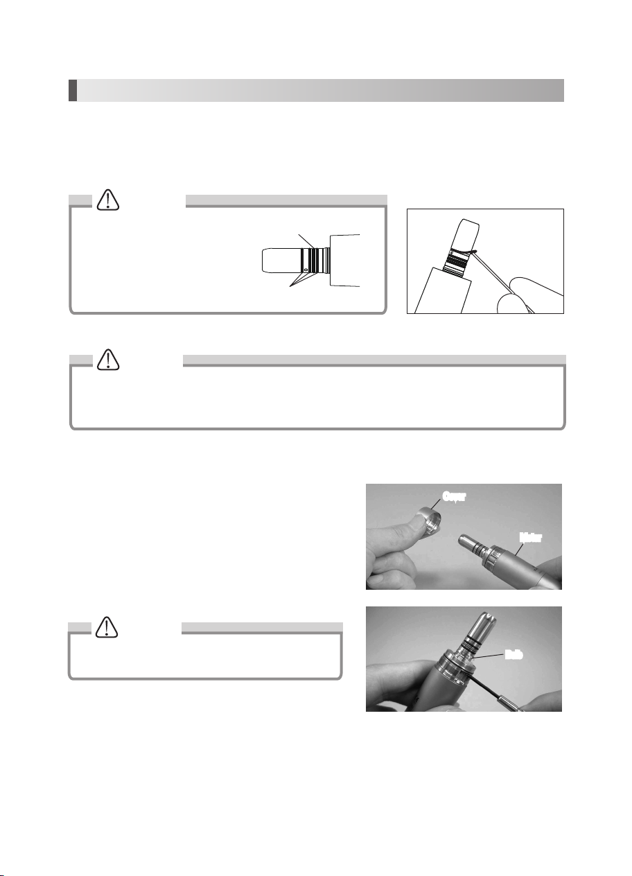
3)Clean the surface of the motor with a soft brush (do not use a metal brush), then wipe with cotton moistened with
isopropyl alcohol.
4)Screw the Motor Cap onto the Motor. Put the Autoclave plug onto the motor insert. (Fig. 10)
5)Autoclavable up to max. 135°C.
ex.)Autoclave for 20 min. at 121°C, or 15 min. at 132°C..
Sterilization at 121°C for more than 15 minutes is recommended by EN13060 or EN ISO17665-1.
Sterilizing the Handpiece Attachments and Burs
1. Wear puncture resistant gloves to prepare attachment for sterilization.
2. Confirm that a bur is in the attachment chuck (never operate attachment without a bur in place)
3. After each patient, flush air and water by running attachment for 20 seconds.
4. Remove bur. Disconnect attachment from motor.
5. Disconnect motor from tubing by unscrewing coupler (counter-clockwise) and pulling motor in the axial direction (direction of E
connector).
6. Clean all external surfaces of attachment and motor using a small toothbrush and soft cloth with isopropyl alcohol.
7. Dry thoroughly, lubricate attachment
8. Sterilize: Note: To Prevent Damage To the Bur, Use an Autoclavable Bur Block.
– Attachments and burs should be autoclaved using one of the following two methods:
a. Three pre-vacuum cycles for 4 minutes at 134°C ± 1 OR
b. Autoclave using the gravitation method for at least 90 minutes at 121°C ± 1
– Follow the manufacturer’s operating manual.
9. Remove attachments and bur(s) from sterilizer after drying cycle ends and allow to cool in bag.
10. Connect motor to tubing.
11. Connect attachment to motor. Install bur.
12. Run attachment for 20 seconds.
Note: An unwrapped attachment, bur and motor need to be used immediately or sterility is not maintained.
Do not exceed the sterilizer manufacturer’s guidelines for load capacity. Use only paper or paper/plastic bags. Always use
complete dry cycle of sterilizer. Always allow product to cool in bag to room temperature prior to using. Contact your sterilizer
manufacturer if moisture remains inside bag and on product after drying.
CAUTION:
Use steam sterilization exclusively for complete sterility. Never dry heat sterilize, ultrasonically clean, expose to chemical
disinfection or cold sterilization by:
• Immersiontechniques
• Surfacewipes,handsoapsordetergents
• Surfacespray
• Attachmentbagsthatcontaindisinfectants
8
Fig.10
Tighten
Autoclave Plug Motor Cap
CAUTION
Fig.11
Fig.12
Fig.13
8. Maintenance
There are 4 O-Rings on the Motor.
The Blue O-Ring is thinner than other
3 O-Rings. Make sure to install in
correct order.
Replace O-Rings if it becomes difficult to connect handpiece attachments or there is an air or water leak.
O-Ring (Blue)
O-Ring (Black)
(1) Changing the Oring
Remove the O-Ring at the Motor Insert with a pointed tool, and mount the new O-Rings into the groove.
CAUTION
Effects of deteriorated O-Rings:
· Air/Water leak · Air/Water does not turn off
· Vibration · Difficult to connect/disconnect the handpiece
(2) Replacing Bulb
1) Turn off the power.
2) Loosen Motor cover and detach it from the motor. Remove
the old light bulb using a small screw driver.
(Fig.12, 13)
3) Align and insert the connector of the new bulb into the
socket hole securely. Screw the Motor cover securely to the
Motor.
CAUTION
• Make sure to turn off the power.
• Do not touch the glass section of new bulb.
Cover
Motor
Bulb
Sterilizing the Handpiece Attachments and Burs
1. Wear puncture resistant gloves to prepare attachment for sterilization.
2. Confirm that a bur is in the attachment chuck (never operate attachment without a bur in place)
3. After each patient, flush air and water by running attachment for 20 seconds.
4. Remove bur. Disconnect attachment from motor.
5. Disconnect motor from tubing by unscrewing coupler (counter-clockwise) and pulling motor in the axial direction (direction of E
connector).
6. Clean all external surfaces of attachment and motor using a small toothbrush and soft cloth with isopropyl alcohol.
7. Dry thoroughly, lubricate attachment
8. Sterilize: Note: To Prevent Damage To the Bur, Use an Autoclavable Bur Block.
– Attachments and burs should be autoclaved using one of the following two methods:
a. Three pre-vacuum cycles for 4 minutes at 134°C ± 1 OR
b. Autoclave using the gravitation method for at least 90 minutes at 121°C ± 1
– Follow the manufacturer’s operating manual.
9. Remove attachments and bur(s) from sterilizer after drying cycle ends and allow to cool in bag.
10. Connect motor to tubing.
11. Connect attachment to motor. Install bur.
12. Run attachment for 20 seconds.
Note: An unwrapped attachment, bur and motor need to be used immediately or sterility is not maintained.
Do not exceed the sterilizer manufacturer’s guidelines for load capacity. Use only paper or paper/plastic bags. Always use
complete dry cycle of sterilizer. Always allow product to cool in bag to room temperature prior to using. Contact your sterilizer
manufacturer if moisture remains inside bag and on product after drying.
CAUTION:
Use steam sterilization exclusively for complete sterility. Never dry heat sterilize, ultrasonically clean, expose to chemical
disinfection or cold sterilization by:
• Immersiontechniques
• Surfacewipes,handsoapsordetergents
• Surfacespray
• Attachmentbagsthatcontaindisinfectants
9
Cover
Motor
Bulb
10
10. Troubleshooting
When trouble is found, check the following again before consulting your dealer. If none of these is applicable or the the
trouble is not remedied even after action has been taken, a failure of this product is suspected.
Check/Remedy Cause Solution
Pilot Lamp does not light.
Power Switch is OFF. Turn ON the switch.
AC Adapter is not connected correctly. Check the connection.
Internal Fuse is blown Contact your dealer.
Motor does not run
Tubing, Motor Cord, AC Adapter is not connected
correctly. Check the connection.
Air pressure is not given, or not at proper level from the
delivery unit. Check the air pressure of the delivery system.
Check the ERROR CODE in the Speed Indicator. Refer to 9. ERROR CODE.
The rotation speed does not rise.
Air pressure is not given, or not at proper level from the
delivery unit. Check the air pressure of the delivery system.
Air pressure of the delivery unit is lower than the “Lower
limit of the air pressure”. Do "6. (1) Foot Air Calibration".
It beeps when switch is turned
on.
You are stepping on the Foot Pedal when turning on the
power switch. (Safety function)
Do not press the Foot Pedal, and turn on the
power switch simultaneously.
Light Bulb does not light.
Light Bulb is not connected correctly. Insert the Light Bulb correctly and firmly. (Refer
to 8. (2) Replacing Bulb)
Light Bulb is burnt-out Please replace the Bulb. (Refer to 8. (2)
Replacing Bulb)
Motor heats up abnormally
during operation. Coolant air is not given, or not at proper level from the
delivery unit. Check the air pressure of the delivery system.
Water leakage
Tubing, Motor Cord is not connected correctly. Check the connection.
If leak is from Control Box, something is wrong within the
Control Box. Contact your dealer.
When turned on, the setting
values are different from what
used to be when turned off. Turned off the motor while rotating. Turn off after the Motor has stopped.
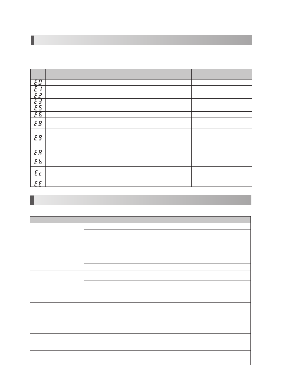
9. Error Code
Error
Code Trouble Cause Check/Remedy
Overcurrent error. (In circuit) Detected overcurrent in the circuit. Contact your dealer.
Overcurrent error. (In software) Detected overcurrent in the software. Contact your dealer.
Retry Error Motor stopped by overload, and not able to restart. Contact your dealer.
ITRIP Error Faulty Motor or Internal circuit. Contact your dealer.
Overvoltage Input Error Overvoltage is given to the Control Box. Contact your dealer.
Bulb voltage Error Overvoltage is given (more than 3.7V) from the Internal circuit. Contact your dealer.
Overheat Error High temperature safe system is functioning, due to long-
time use at a high load. Allow unit to cool and try again.
Motor Start Error
- Motor didn't reach the preset speed in a prescribed
period of time.
- Break down of a motor cord wire, or internal circuit
malfunction.
Contact your dealer.
Bulb voltage Error Voltage for the Bulb did not reach the preset level in a
prescribed period of time. Contact your dealer.
Air Offset Error Lower than preset " Lower limit of the air pressure" Displayed by Foot Air Calibration
function. Not a malfunction.
Air Full Scale Error - Higher than preset "Upper limit of the air pressure".
- Air pressure higher than 0.4MPa (=4.0kgf/cm2=56.89psi)
is given.
Displayed by Foot Air Calibration
function. Not a malfunction.
EEPROM Error Malfunction of the memory for the setting values. Contact your dealer.
If the motor stops due to an abnormality such as a malfunction, overload, breakage or incorrect usage, the Control Box will
display an error code on the Speed Indicator. If an error code is displayed, turn on the power again and check whether the
same error code is displayed. If the same error code is displayed, take action by referring to the instructions provided in
the "Check/Remedy" column in the following table.
11
11. StarDental Limited Warranty
NuTorque®Lite Control Box Unit, motor, hose and transformer are warranted against defects in material and workmanship
for 3 years from date of purchase. Attachments - 1:1 AL, 1:1 AC, 16:1 AL, 1:5 Miniature Head AC, 1:5 Standard Head AC, 1:1
Straight - are warranted against defects in material and workmanship for 12 months from date of purchase.
Please note the following additional terms of our warranty and return policy:
• Warranties cover manufacturing defects only and do not cover defects resulting from abuse, improper handling, cleaning,
care or maintenance, normal wear and tear, or non-observance of operating, maintenance or installation instructions.
Failure to use authorized parts or an authorized repair facility voids this warranty.
• Liability is limited to repair or replacement of the defective product at our sole discretion. All other liabilities, in particular
liability for damages, including, without limitation, consequential or incidental damages are excluded.
• This warranty is in lieu of all other warranties, expressed or implied, including any implied warranties of merchantability or
fitness for a particular purpose. No employee, representative or dealer is authorized to change this warranty in any way or
to grant any other warranty.
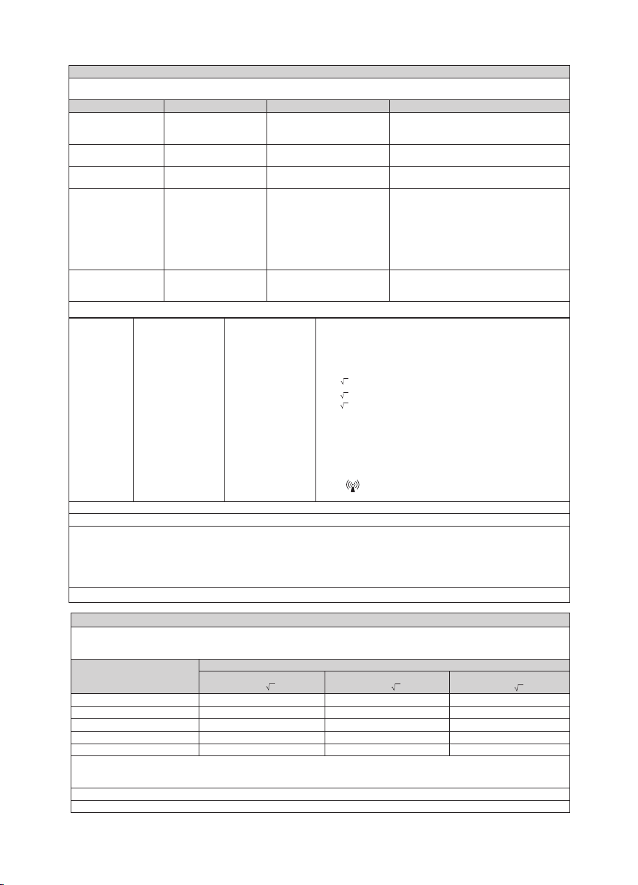
Guidance and manufacturer's declaration - electromagnetic emissions
The NuTorque Lite is intended for use in the electromagnetic environment specified below. The customer or the user of the NuTorque Lite and manual should
assure that it is used in such an environment.
Emissions test Emissions test Electromagnetic environment - guidance
RF emissions CISPR11 Group 1 The NuTorque Lite uses RF energy only for its internal function. Therefore, its RF emissions are very low
and are not likely to cause any interference in nearby electronic equipment.
RF emmissions CISPR11 class B The NuTorque Lite is suitable for use in all establishments, including domestic estabilishments and those
directly connected to the public low-voltage power supply network that supply network that supplies
buidings used for domestic purposes.
(*)This applies to the AC230V system. For AC120V system, this is “Not applicable”.
Harmonic emissions
IEC61000-3-2
class A (*)
Voltage fluctuations/flicker
emissions IEC61000-3-3
Complies (*)
12. Disposing Product
Disposal of equipment and accessories at the end of their service lives:
On the basis of EC Directive 2002/96/EC on Waste Electrical and Electronic Equipment, we would like to point out that
this product is not subject to this Directive but may be disposed of in Europe in special waste management centres.
Additional information can be obtained from the manufacturer or your dental supplier.
This product has to be recycled or disposed of in a way that is harmless for human beings and the environment; in doing
so, the national valid regulations are to be observed.
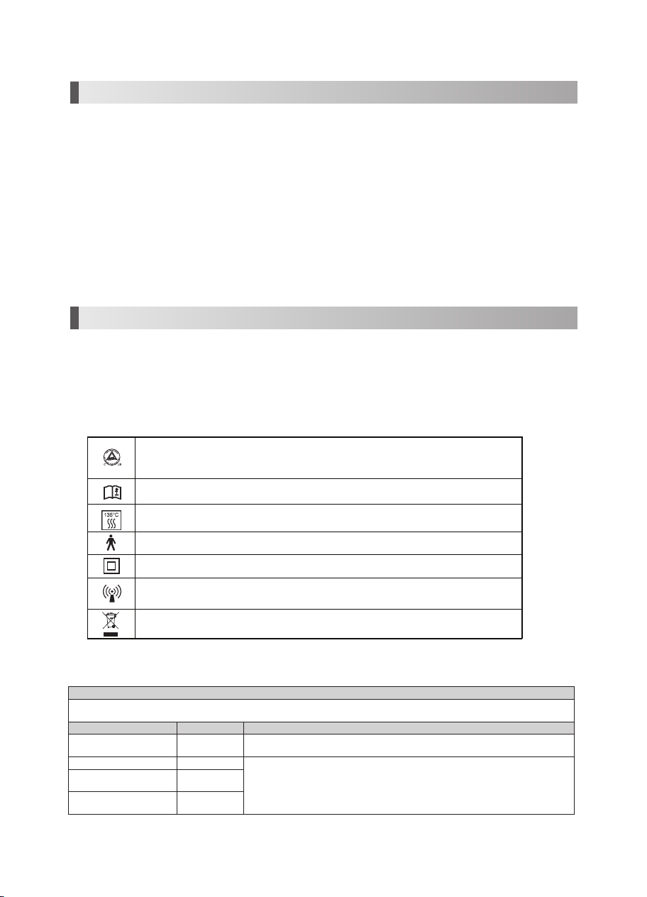
Symbols
TUV Rhineland of North America is a Nationally Recognized Testing Laboratory (NRTL) in the
United States and is accredited by the Standards Council of Canada to certify electro-medical
products with Canadian National Standards
Consult Operation Instructions
Autoclavable up to Max. 135 °C. For detail, see Sterilization.
Type B applied part
Class II Equipment
Marking on the outside of equipment or equipment parts that include RF transmitters or that apply
RF electromagnetic energy for diagnosis or treatment
Follow the wast of electric and electronic equipment (WEEE) Directive (2002/96/EC) to dispose of
the product and accessories
12
Recommended separation distances between portable and mobile RF communications equipment and the NuTorque Lite
The NuTorque Lite is intended for use in an electromagnetic environment in which radiated RF disturbances are controlled. The customer or the user of the
NuTorque Lite can help prevent electromagnetic interference by maintaining a minimum distance between portable and mobile RF communications equipment
(transmitters) and the NuTorque Lite as recommended below, according to the maximum output power of the communications equipment.
Rated maximum output power of transmitter
W
Separation distance according to frequency of transmitter
150kHz to 80MHz
d=1.2 P
80MHz to 800MHz
d=1.2 P
800MHz to 2.5GHz
d=2.3 P
0.01 0.12 0.12 0.23
0.1 0.38 0.38 0.73
1 1.2 1.2 2.3
10 3.8 3.8 7.3
100 12 12 23
For transmitters rated at a maximum output power not listed above, the recommended separation distance d in meters (m) can be estimated using the
equation applicable to the frequency of the transmitter, where P is the maximum output power rating of the transmitter in watts (W) according to the transmitter
manufacturer.
NOTE 1 At 80 MHz and 800 MHz, the separation distance for the higher frequency range applies.
NOTE 2 These guidelines may not apply in all situations. Electromagnetic propagation is affected by absorption and reflection from structures, objects and people.
Conducted RF
IEC61000-4-6
Radiated RF
IEC61000-4-3
3Vrms
150 kHz to 80MHz
3V/m
80MHz to 2.5 GHz
3Vrms
3V/m
Portable and mobile FRO communications equipment should be used no closer
to any part of the NuTorque Lite, including cables, than the recommended
separation distance calculated from the equation applicable to the frequency of
the transmitter.
Recommended separation distance
d = 1.2 P
d = 1.2 P 80MHz to 800MHz
d = 2.3 P 800MHz to 2.5GHz
Where
P
is the maximum output power rating of the transmitter in watts
(W)according to the transmitter manufacturer and
d
is the recommended
separationdistance in meters (m).
Field strengths from fixed RF transmitters as determined by an electromagnetic
site surveya, should be less than the compliance level in each frequency rangeb,
Interference may occur in the vicinity of equipment marked with the following
symbol:
NOTE 1 At 80MHz and 800MHz, the higher frequency range applies.
NOTE 2 These guidelines may not apply in all situations. Electromagnetic propagation is affected by absorption and reflection from structures, objects and people.
a
Field strengths from fixed transmitters, such as base stations for radio (cellular/cordless) telephones and land mobiles radios, amateur radio, AM and FM radio
broadcast and TV broadcast cannot be predicted theoretically with accuracy. To assess the electromagnetic environment due to fixed RF transmitters, an
electromagnetic site survey should be considered. If the measured field strength in the location in which the NuTorque Lite is used exceeds the applicable RF
compliance level above, the NuTorque Lite should be observed to verity normal operation. If abnormal performance is observed, additional measures may be
necessary, such as reorienting or relocating the NuTorque Lite .
b Over the frequency range 150kHz to 80MHz, field strengths should be less than 3 V/m.
Guidance and manufacturer's declaration - electromagnetic immunity
The NuTorque®Lite is intended for use in the electromagnetic environment specified below. The customer or the user of the NuTorque Lite and manual should
assure that it is used in such an environment.
Immunity test IEC60601 test level Compliance level Electromagnetic environment - guidance
Electrostatic discharge (ESD)
IEC61000-4-2
±6kV contact
±8kV air
±6kV contact
±8kV air
Floors should be wood, concrete or ceramic tile. If floors
are covered with synthetic material, the relative humidity
should be at least 30%.
Electrical fast transient/burst
IEC61000-4-4
±2kV for power supply lines
±1kV for input/output
±2kV for power supply lines
No input/output line
Mains power quality should be that of a typical
commercial or hospital environment.
Surge IEC61000-4-5 ±1kV line(s) to line(s)
±2kV line(s) to earth
±1kV line to line
±2kV lines to earth
Mains power quality should be that of a typical
commercial or hospital environment.
Voltage dips, short
interruptions and voltage
variations on power supply
input lines IEC61000-4-11
<5% Ut
(>95% dip in Ut) for 0.5 cycle
40% Ut
(60% dip in Ut) for 5 cycles
70% Ut
(30% dip in Ut) for 25 cycles
<5% Ut
(>95% dip in Ut) for 5 sec
<5% Ut
(>95% dip in Ut) for 0.5 cycle
40% Ut
(60% dip in Ut) for 5 cycles
70% Ut
(30% dip in Ut) for 25 cycles
<5% Ut
(>95% dip in Ut) for 5 sec
Mains power quality should be that of a typical
commercial or hospital environment. If the user of the
NuTorque Lite requires continued operation during power
mains interruptions, it is recommended that the NuTorque
Lite be powered from an uninterruptible power supply or
a battery.
Power frequency (50/60Hz)
magnetic field IEC61000-4-8
3 A/m 3 A/m Power frequency magnetic fields should be at levels
characteristic of a typical location in a typical commercial
or hospital environment.
NOTE: Ut is the a.c. mains voltage prior to application of the test level.

13
NuTorque®Lite Electric Handpiece System ........................................................................................ 265289
Control Box.......................................................................................................................................... 265316
Motor ................................................................................................................................................... 265317
AC Adapter (120V) .............................................................................................................................. 265290
AC Adapter (230V) .............................................................................................................................. 265291
Motor Tubing ....................................................................................................................................... 265326
O-Ring Kit for Motor............................................................................................................................. 265321
Motor Cap Kit, for sterilization ............................................................................................................. 265322
Replacement Lamp Kit ........................................................................................................................ 265324
Replacement Cord Kit ......................................................................................................................... 265325
1:1 Electric Friction Grip Attachment with Autochuck.......................................................................... 263981
1:5 Electric Friction Grip Attachment with Autochuck.......................................................................... 263982
1:5 Mini Electric Friction Grip Attachment with Autochuck .................................................................. 263983
1:1 Electric Attachment with AutoLatch............................................................................................... 263984
16:1 Electric Attachment with AutoLatch............................................................................................. 263985
1:1 Electric Straight Attachment ..........................................................................................................263986
Description
Always insist on StarDental parts for best performance.
11. Replacement Parts
65292 Rev C Date of Issue: 2019/02/15
For new products, manuals and technical information call 1-866-DTE-INFO or visit our web site @www.dentalez.com
StarDental®
Division of DentalEZ Inc.
1816 Colonial Village Lane
Lancaster, PA 17601 U.S.A.
Printed in Japan
©2019 - DentalEZ Inc.
Anyone wishing to return any DentalEZ Inc. product to a DentalEZ facility MUST obtain the proper RETURN
AUTHORIZATION NUMBER from the Customer Service Department.
The RA Number must appear clearly marked on both the outside and inside of the returned product carton.
When calling for a return authorization number you will be asked to provide the following information:
Items will be evaluated. Return Authorization Number is not a guarantee for credit. Your cooperation with this
procedure will help us expedite processing of any returns. To Obtain A Return Authorization Number, Call
1-866-DTE-INFO
• Product Name, Model Number or Part Number
• Serial Number of Product
• Dealer Return Purchase Order Number
• Reason For Return
• Copy of Invoice Showing Purchase
Item Number
Table of contents
Other StarDental Dental Equipment manuals


Popular Dental Equipment manuals by other brands


KaVo
KaVo EXPERTmatic LUX contra-angle E25 L Instructions for use

Woodpecker
Woodpecker LED.F instruction manual

Dentsply Sirona
Dentsply Sirona Nupro Freedom Directions for use

Poldent
Poldent Endostar Instructions for use

Olsen
Olsen Logic Operation guide

Coltene
Coltene CanalPro Apex Locator Compact Instructions for use


