Starline ROLDECK 3 User manual
RDBIPB.MM.03
INSTRUCTION MANUAL IN-POOL BENCH
MONTAGEANLEITUNG WINKELVERKLEIDUNG
MONTAGEHANDLEIDING HOEKKAP
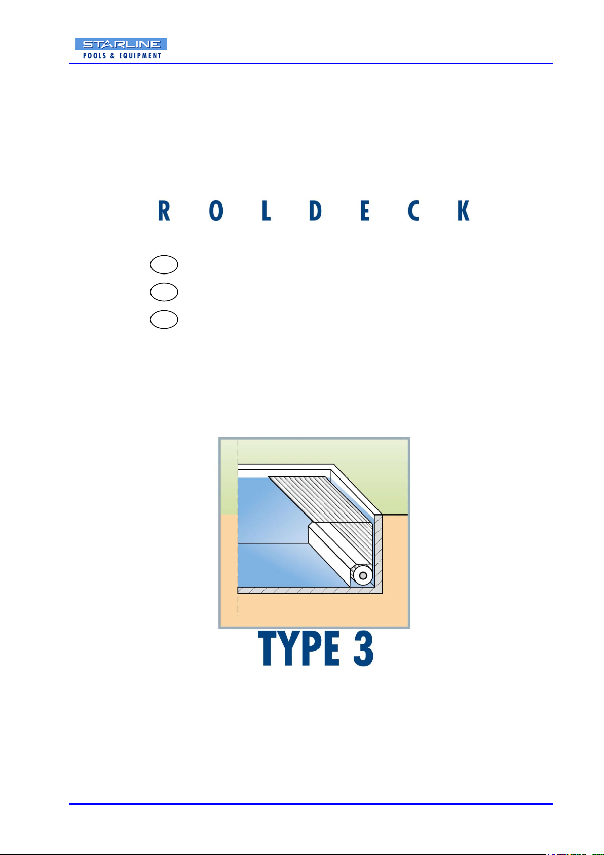
STARLINE ROLDECK
NL
D
GB

RDBIPBMM.03 1
PLEASE RETAIN THESE ASSEMBLING INSTRUCTIONS FOR FUTURE REFERENCE
If you have any queries concerning the duration and terms of the guarantee, please contact your supplier.
We would also refer you to our General Sale and Supply Conditions, which are available on request.
The manufacturer accepts no liability for any damage or injury caused by failure to follow these instructions,
or from negligent operation or Assembling, even if this is not expressly stated in this instruction manual.
In light of our policy of continuous improvement, it is possible that details of the product may differ from
those described in this manual. For this reason, these instructions should only be treated as guidelines for
the installation of the relevant product. This manual has been compiled with all due care, but the
manufacturer cannot be held responsible for any errors or the consequences thereof. All rights are
reserved and no part of this manual may be reproduced in any way.
BITTE VERWENDEN SIE DIESE ANLEITUNG BEI ALLEN ZUKÜNFTIGEN MONTAGEN !
Bezüglich Gewährleistungsdauer und für die Bedienungseinweisung wenden Sie sich bitte an Ihren
Händler.
Des weiteren verweisen wir auf unsere Allgemeinen Verkaufs- und Lieferbedingungen, die wir Ihnen auf
Anfrage gerne zur Verfügung stellen.
Für Folgeschäden, bedingt durch unsachgemäße Montage bzw. Nichteinhaltung der in dieser
Montageanleitung aufgeführten Vorschriften und entsprechenden Vorsichtsmaßnahmen, ist der Hersteller
nicht verantwortlich.
Auf Grund von kontinuierlicher Weiterentwicklung der Produkte kann es durchaus vorkommen, dass das
Produkt in Einzelheiten von dem Beschrieb abweicht. Aus diesem Grund dient die Anleitung nur als
Richtlinie für die Montage der Produkte.
Wir haben diese Montageanweisung sorgfältig verfasst, übernehmen aber für evtl. Fehler, oder
Folgeschäden keine Verantwortung.
Wir weisen ausdrücklich darauf hin, dass alle Rechte vorbehalten sind, und das Kopieren dieser Anleitung
verboten ist.
BEWAAR DEZE MONTAGEHANDLEIDING VOOR TOEKOMSTIG GEBRUIK!
Voor de duur en de voorwaarden ten aanzien van garantie raden wij u aan contact op te nemen met uw
leverancier. Voorts verwijzen wij naar onze Algemene Verkoop- en Leveringsvoorwaarden die op aanvraag
verkrijgbaar zijn.
Alle verantwoordelijkheid voor schade of letsel als gevolg van het niet naleven van deze voorschriften, of
door het niet in acht nemen van de gebruikelijke voorzichtigheid of zorgvuldigheid bij handelingen en
montage, zelfs indien niet uitdrukkelijk omschreven in deze montagehandleiding, wordt door de fabrikant
afgewezen.
Als gevolg van voortdurend streven naar verbetering kan het voorkomen dat het product in detail afwijkt
van hetgeen in deze handleiding is beschreven. Om deze reden dienen de gegeven instructies slechts als
richtlijn voor het installeren van het in deze handleiding vermelde product.
Deze handleiding is met alle zorg samengesteld, maar de fabrikant kan geen verantwoording op zich
nemen voor eventuele fouten in deze handleiding of voor de gevolgen daarvan.
Voorts zijn alle rechten voorbehouden en mag niets uit deze handleiding op welke wijze dan ook worden
verveelvoudigd.
NL
D
GB

RDBIPBMM.03 2
Table of contents / Inhaltsverzeichnis / Inhoudsopgave
1. Introduction / Einleitung / Inleiding 3
2. Warnings & safety measures / Warnungen und Sicherheitsmassnahmen / 3
Veiligheidsmaatregelen en waarschuwingen
3. Assembly preparations / Montagevorbereitung / Montagevoorbereiding 6
3.1 Roller / Wickelwelle / Opwikkelas 6
3.2 In-In-Poolbench / Winkelverkleidung / hoekkap 6
4. Checking tools / Kontrolle der Werkzeuge / Controle gereedschappen 7
5. Checking fasteners / Kontrolle Befestigungsteile / Controle bevestigingsmaterialen 8
5.1 Roller / Wickelwelle / Opwikkelas 8
5.2 In-In-Poolbench / Winkelverkleidung / hoekkap 11
6. Exploded-view Roller / Wickelwelle / opwikkelas 12
7. Exploded-view In-Poolbench / Winkelverkleidung / hoekkap < 5000 ( 600-750 - 850-1000) 13
8. Exploded-view In-Poolbench / Winkelverkleidung / hoekkap > 5000-10000( 600-750 - 850-1000)14
9. List of components / Stücklistet / Stuklijst 15
9.1 Roller / Wickelwelle / Opwikkelas 15
9.2 In-In-Poolbench / Winkelverkleidung / hoekkap 16
10. Measuring Pool / messen Becken / inmeten bad 17
11. Assembling Situation 1 / Montage Situation 1 / Montage situatie 1 18
12. Assembling Situation 2 / Montage Situation 2 / Montage situatie 2 23
13. Assembling Situation 3 / Montage Situation 3 / Montage situatie 3 27
14. Assembling In-In-Poolbench / Montage Winkelverkleidung / Montage hoekkap < 5000 31
15. Assembling In-In-Poolbench / Montage Winkelverkleidung / Montage hoekkap > 5000-10000 38
Copyrights 44
RDBIPBMM.03 3
1. Introduction
This manual describes the Assembling of the Starline Roldeck. Read this manual carefully. The installer
must be informed of the contents of this manual. Follow the contents of the manual precisely. Always do
things in the correct order. This manual should be kept on a safe, dry and against sun-protected place.
In case of damage or loss the user may request a new copy of the manual from Starline.
2. Warnings & safety measures
When installing the Starline Roldeck, please observe carefully the instructions and guidelines contained in
this manual. Always perform each step in sequence. If any of the instructions are not clear, please contact
Starline. Subject to technical change without notice. All measurements are in millimetres unless otherwise
indicated.
The Starline Roldeck should normally be assembled by qualified technical personnel (at least 2 skilled
people). We strongly discourage the use of additional components or the omission of components as this
can have a negative effect on the operation and the safety of the Starline Roldeck.
The manufacturer accepts no liability for damage or injury caused by failure to adhere strictly to the safety
precautions and instructions contained in this manual or by negligence during the installation of the product
and any accessories described in this document.
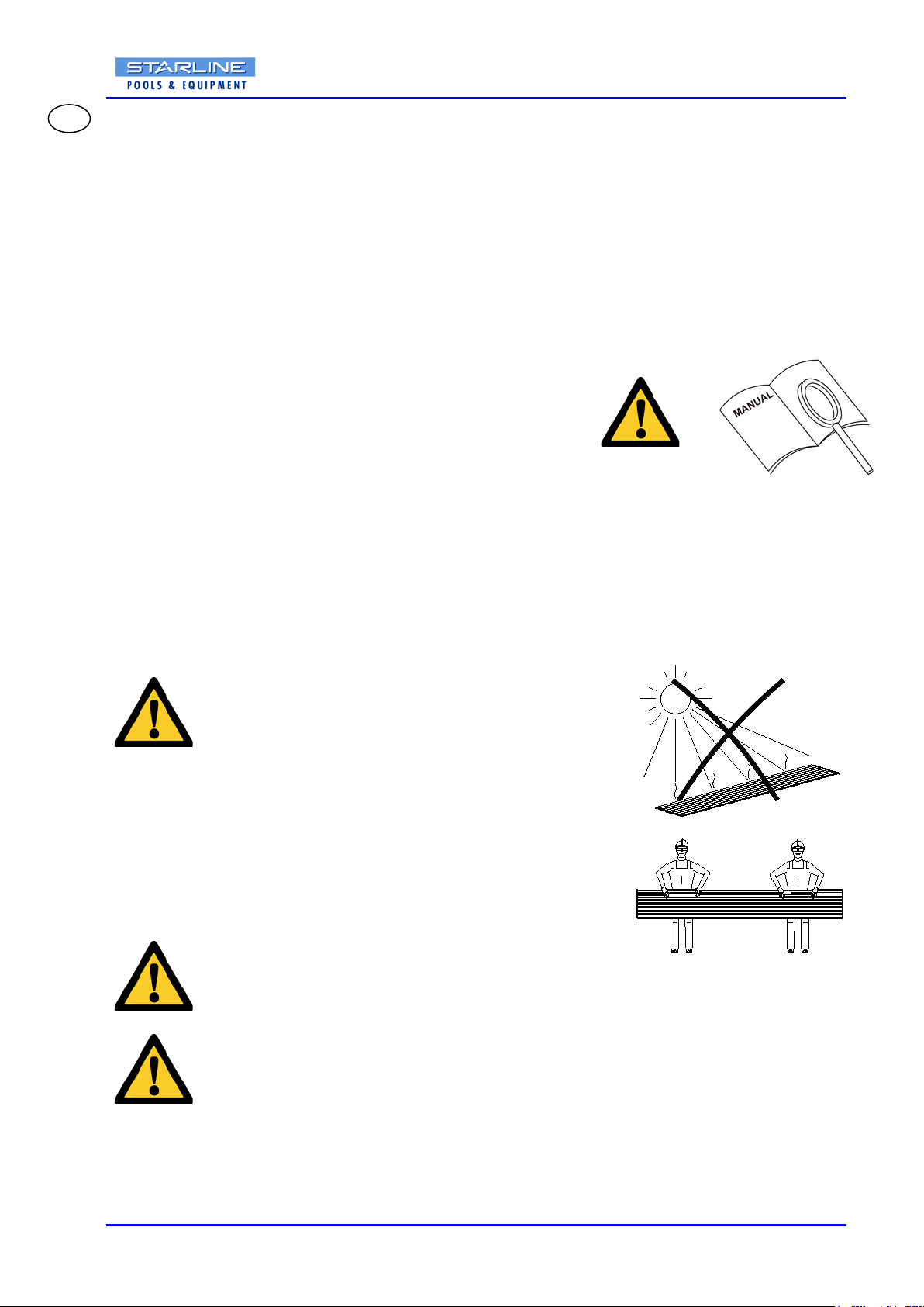
Please note: At low temperatures one cannot transport, dis/assemble, clean and replace the slats. At
low temperatures the slats are very vulnerable.
Translucent, solar and blue slats should not be exposed to
direct sunlight, unless lying on the water-level.
The translucent, solar and blue slats must always be placed
on or under the water level or rolled on the winding shaft
so that these are protected against sunlight.
The slats should only be transported horizontally, by
min. 2 qualified employees.
Condensation can occur in the slats.
The electrical installation must compliance to the current standards and locally applying
installation instructions. The installation should only be connected by an acknowledged
electro technical installer. Possible failures to equipment must be communicated to your
installer. The equipment should be checked 1x p. year by your installer.
GB
RDBIPBMM.03 4
1. Einleitung
Diese Anleitung beschreibt den Zusammenbau des Starline Roldeck. Lesen Sie diese Anleitung sorgfältig.
Der Installateur muß vom Inhalt diese Anleitung informiert sein. Der Inhalt der Anleitung folgt genau. Tun
Sie immer Sachen im korrekten Auftrag. Diese Anleitung sollte auf sicherem, trockenem und an einen
geschützten Platz vor der Sonne gehalten werden. Wenn Sie die Anleitung verlieren sollten, bestellen Sie
dann eine neue Kopie.
2. Warnungen und Sicherheitsmassnahmen
Befolgen Sie für die Montage des Starline Roldeck sorgfältig die Anweisungen und Vorgaben wie
beschrieben. Verändern Sie auf keinen Fall die Reihenfolge der Montageschritte.
Sollten dennoch Probleme auftreten, wenden Sie sich bitte direkt an Starline.
Wir behalten uns vor, auch ohne schriftliche Ankündigung, Änderungen vorzunehmen.
Sofern nicht anders erwähnt, sind alle Maßangaben in Millimeter.
Für die ordentliche Montage sind mindestens zwei qualifizierte Monteure notwendig.
Das eigenständige Hinzufügen oder Weglassen von Montageteilen kann einen nachteiligen Einfluss auf die
Funktionsfähigkeit und Sicherheit der Elemente zur Folge haben und ist deshalb strengstens untersagt.
Der Hersteller lehnt jede Verantwortung für Schäden oder Verletzungen, die durch die unsachgemässe
Handhabung, das Nichteinhalten der Sicherheitsvorschriften und die fehlerhafte Montage, entstehen ab.
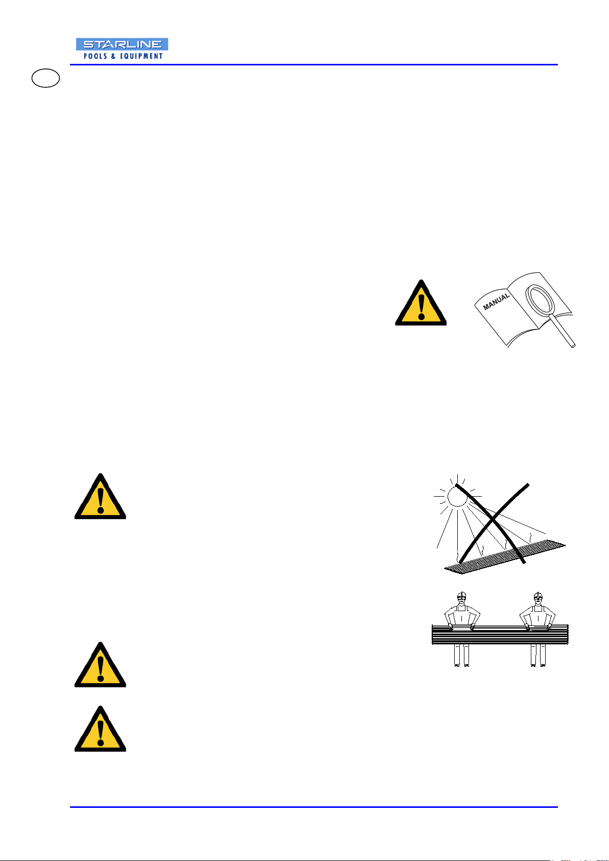
Achtung: Bei niedrigen Temperaturen kann man die Lamellen nicht transportieren, ab/montieren,
reinigen und ersetzten. Bei niedrigen Temperaturen sind die Lamellen sind sehr
zerbrechlich.
Die Transparente, Solar- und Blaue Lamellen sollten nicht
an direktem Sonnenlicht herausgestellt werden, außer liegend
auf dem Wasserbereich.
Die Transparente, Solar- und die Blau Lamellen müssen immer
auf oder unter Wasserbereich sein. Oder aufgerollt auf der
Wickel damit diese geschützt sind gegen Sonnenlicht.
Die Lamellen sollten nur horizontal transportiert werden, durch
min. 2 qualifizierten Angestellten.
Kondensation kann stattfinden in die Lamellen.
Die elektrische Installation sollte den gegenwärtigen Standards und Montagevorschriften
am Ort entsprechen. Die Installation sollte nur durch einen bestätigten elektrotechnischen
Installateur angeschlossen werden. Mögliche Störungen zur Ausrüstung sollten Sie Ihrem
Installateur mitteilen. Lassen Sie die Ausrüstung 1x pro Jahr durch Ihren Installateur
überprüfen.
D
RDBIPBMM.03 5
1. Inleiding
Deze handleiding beschrijft de montage van het Starline Roldeck.
Lees deze handleiding zorgvuldig. De installateur moet van de inhoud van deze handleiding op de hoogte
zijn. Volg de inhoud van de handleiding nauwgezet op.
Verricht de handelingen altijd in de juiste volgorde.
Deze handleiding dient op een veilige, droge en tegen zon beschutte plaats bewaard te worden.
Mocht de handleiding zoekraken bestel dan een nieuw exemplaar.
2. Veiligheidsmaatregelen en waarschuwingen
Volg bij de installatie van de het Starline Roldeck de instructies en richtlijnen zoals omschreven zijn in deze
handleiding. Wijzig nooit de volgorde van de te verrichten handelingen.
Indien een of ander niet duidelijk is omtrent montage neem dan contact op met Starline.
Technische wijzigingen voorbehouden, zonder schriftelijke melding.
Alle maataanduidingen zijn in millimeters tenzij anders vermeld.
De montage van het Starline Roldeck dient standaard door gekwalificeerd technisch personeel (minimaal
2 vakbekwame personen) te worden uitgevoerd.
Het toevoegen of weglaten van onderdelen kan een nadelige invloed hebben op het functioneren en
veiligheid en wordt dus ten strengste afgeraden!
De fabrikant aanvaardt geen enkele aansprakelijkheid voor schade of letsel veroorzaakt door het
niet (strikt) naleven van de veiligheidsvoorschriften en -instructies in deze handleiding, dan wel door
onachtzaamheid tijdens installatie van het in dit document vermelde product en de eventueel bijbehorende
accessoires.
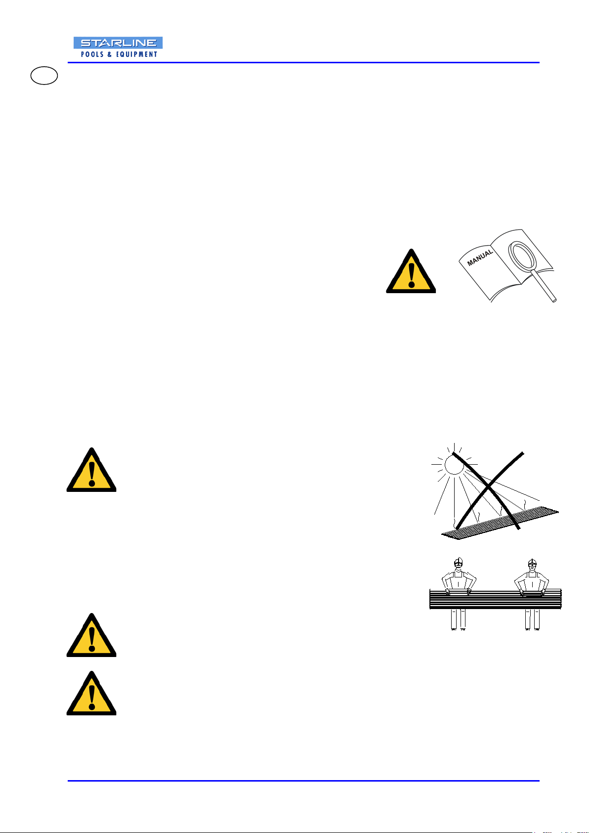
Let op: Bij lage temperaturen mag men de lamellen niet transporteren, de/monteren, reinigen en
vervangen. Bij lage temperaturen zijn de lamellen zeer kwetsbaar.
Transparante, solar en blauwe lamellen niet blootstellen aan
direct zonlicht, tenzij liggend op het wateroppervlak.
De transparante, solar en blauwe lamellen moeten ten aller tijden
op of onder het wateroppervlak liggen of op de opwikkelas
gerold zijn, zodat deze tegen zonlicht beschermd wordt.
De lamellen mogen alleen horizontaal getransporteerd worden
met minimaal 2 gekwalificeerde werknemers.
Er kan condens in de lamellen ontstaan.
De elektrische installatie moet voldoen aan de huidige normen en plaatselijk geldende
installatie- voorschriften. De installatie mag alleen aangesloten worden door een erkend
elektrotechnisch installateur.
Eventuele storingen aan de apparatuur dient u te melden aan uw installateur. Laat de
apparatuur 1x per jaar door uw installateur controleren.
NL

RDBIPBMM.03 6
3. Assembling preparations
3.1 Roller
Check at the start of the activities by means of the component list if all materials and components are
present. If not, take direct contact with your supplier.
PLEASE NOTE: The Assembling of the roller exists from one of the following 3 situations:
- SITUATION 1: In-roller motor cable through the wall
-SITUATION 2: In-roller motor retro fit
-SITUATION 3: External motor (wall transit)
Specify your situation (see page 12) and go to the chapter in which the Assembling of this situation is
described.
3.2 In-Poolbench
PLEASE NOTE: The In-Poolbench consist of dimensions < 5000 mm (type 600-750 or 850-1000) or
dimensions > 5000 –10000 mm (type 600-750 or 850-1000), specify your type (see page 13 / 14) and go to
the chapter in which the Assembling of this type is described.
3. Montagevorbereitung
3.1 Wickelwelle
Überprüfen Sie beim Anfang der Tätigkeiten mittels des Bauteilverzeichnisses ob alle Materialen und
Bestandteilen vorhandensein. Wenn nicht, Suchen Sie direkt Kontakt mit Ihrem Lieferanten.
BITTE BEACHTEN: Der Zusammenbau die Wickelwelle besteht von einer der folgenden 3 Situationen:
- SITUATION 1: Montage des Rohrmotors Anschluss durch der Beckenwand
-SITUATION 2: Montage des Rohrmotors Anschluss entlang der Beckenwand
-SITUATION 3: Externer Motor (Wanddurchfahrt)
Vereinbaren Sie Ihre Situation (Siehe Seite 12) und gehen Sie zum Kapitel, in dem der Zusammenbau
dieser Situation beschrieben wird.
3.2 Winkelverkleidung
BITTE BEACHTEN: Der Winkelverkleidung besteht von abmessung < 5000 mm (type 600-750 oder 850-
1000) oder abmessung > 5000 –10000 mm (type 600-750 or 850-1000), vereinbart Ihre Art (Siehe Seite 13
/ 14) und geht zum Kapitel, in dem der Zusammenbau dieser Art beschrieben wird.
3. Montagevoorbereiding
3.1 Opwikkelas
Controleer bij aanvang van de werkzaamheden middels de onderdelenlijst of alle materialen en
onderdelen aanwezig zijn. Zo niet, direct contact opnemen met uw leverancier.
LET OP: De montage van de opwikkelas bestaat uit één van de volgende 3 situaties:
- SITUATIE 1: Buismotor kabel door de wand
-SITUATIE 2: Buismotor kabel langs de wand
-SITUATIE 3: Externe motor (muurdoorvoer)
Bepaaluwsituatie (zie pagina 12) en ga naar het hoofdstuk waarin de montage van deze situatie wordt
beschreven.
3.2 Hoekkap
LET OP: De hoekkap bestaat uit afmetingen < 5000 mm (type 600-750 of 850-1000) of afmetingen > 5000
– 10000 mm (type 600-750 of 850-1000). Bepaal uw type (zie pagina 13 / 14) en ga naar het hoofdstuk
waarin de montage van dit type wordt beschreven.
NL
D
GB

RDBIPBMM.03 7
4. Checking tools / Kontrolle der Werkzeuge / Controle gereedschappen
S13/S17/S19
Ø 3/6/10
S13/S17/S19 S3/S5/S6
Ø25/35/60/70
SITUATIE 3 / SITUATION 3
SITUATIE 2 / SITUATION 2
T40

RDBIPBMM.03 8
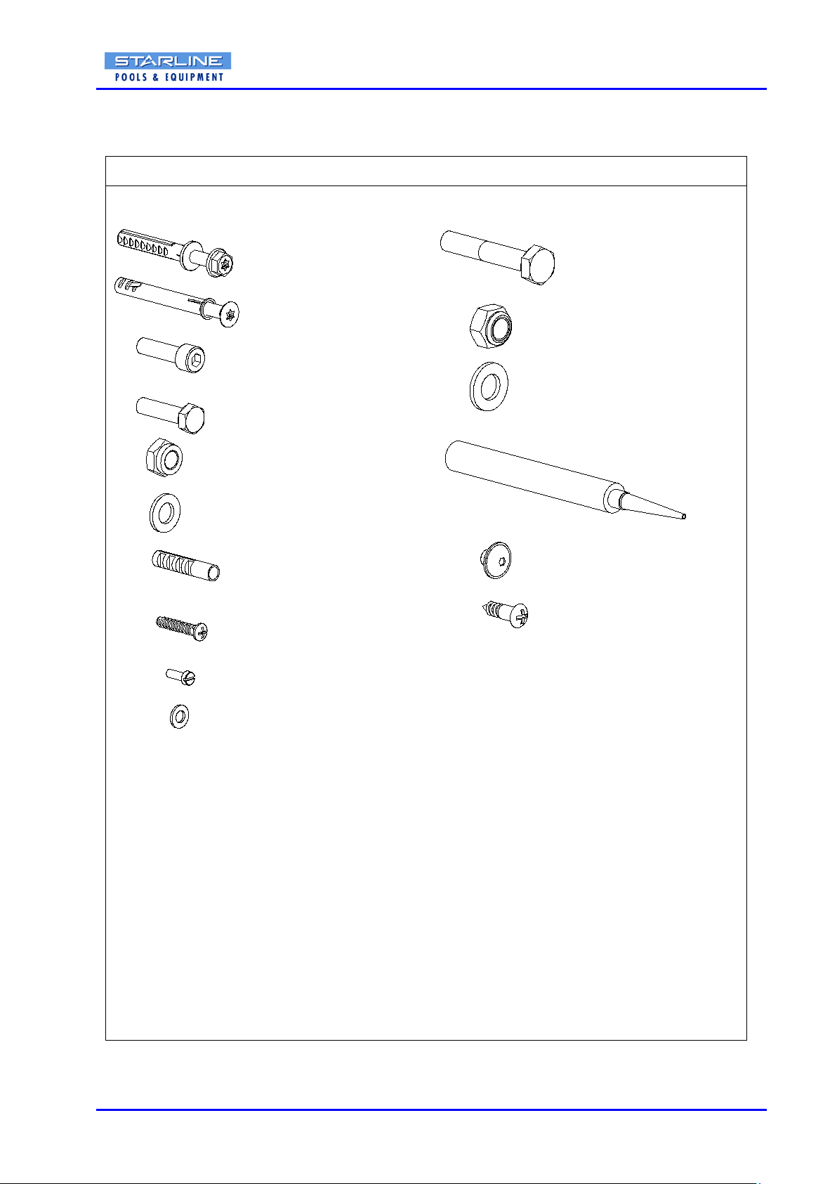
5. Checking fasteners / Kontrolle Befestigungsteile / Controle bevestigingsmaterialen
5.1 Roller / Wickelwelle / Opwikkelas
Ø22-30 (1x)
(1x)
(1x)
M12
(4x / 7x )
M10 x 20
(1x) (2x)
M12
(2x)
M12 x 75
10 x 60
10 x 80
(4x / 8x) (2x)
SITUATION 1 / SITUATIE 1
DIN 912
DIN 931
DIN 985
DIN 125
(1x)
PTFE-TAPE
(2x)
(2x)
M10 DIN 125
M10 DIN 985
M10 x 30 DIN 933
(4x)
M6 x 12 DIN 84
M6 DIN 125
RDBIPBMM.03 9
Ø 6 x 30 mm M6 x 6
ST 4 x 25
(4x)
(2x)
(2x)
M12 x 75
(2x)
M10 x 20
(1x)
(2x)
M12
M12
(2x)
(1x)
DIN 912
DIN 7981
DIN 931
DIN 985
DIN 125
ISO 7380
SITUATION 2 / SITUATIE 2
(2x)
(2x)
M10 DIN 125
M10 DIN 985
M10 x 30 DIN 933
(4x)
M6 x 12 DIN 84
(4x / 8x)
10 x 60
M6 DIN 125
10 x 80
(4x / 7x )
DIN 7981
ST 4.8x16
(2x)

RDBIPBMM.03 10
(3x)
DIN 125
M10
(1x)
(1x)
(1x)
M10 x 70 DIN 933
(4x)
(2x)
DIN 985
M10
DIN 933
M10 x 30
DIN 933
M8 x 10
SITUATION 3 / SITUATIE 3
DIN 125
M12
(2x)
(2x)
M12 DIN 985
(2x)
M12 x 75 DIN 931
M8 x 70 DIN 933
(2x)
M8
(2x)
DIN 125
M8
(2x)
M8 x 30 DIN 933
NF E25-513
M8
(2x)
(2x)
(5x)
DIN 933
(1x)
M10 x 70
(1x)
M12 x 80 DIN 933
or
M6 x 12 DIN 84
(4x / 8x)
10 x 60
M6 DIN 125

RDBIPBMM.03 11
5.2 In-Poolbench / Winkelverkleidung / hoekkap
(6x)
(4x)
DIN 933
M8 x 20
M8 x 40 ISO 7380
(4x)
(4x)
ST 3.9 x 13 DIN 7981C
(32x)
DIN 9021
M8
(48x)
DIN 934
M8
M8
DIN 933M8 x 65
M8 DIN 440 R
(6x)
(6x)
(6x)
(8x)
(2x)
M8 x 40 ISO 7380
(2x)
ST 3.9 x 13 DIN 7981C
(8x)
M8 DIN 9021
M8 DIN 934
M8
M8 x 65 DIN 933
M8
(6x)
DIN440 R
(6x)
M8 x 40
(2x) ISO 7380
ST 3.9 x 13
(2x) DIN 7981C
M8
(6x)
(8x)
M8
(8x) DIN 9021
M8 DIN 934
(6x)
M8 DIN 440 R
(6x)
M8 x 65 DIN 933
< 5000 mm ( 600 - 750) < 5000 mm ( 850 - 1000)
(6x)
(4x)
M8 x 20 DIN 933
ISO 7380
M8 x 40
(4x)
(4x) DIN 7981C
ST 3.9 x 13
(32x)
M8 DIN 9021
(48x)
M8 DIN 934
M8
M8 x 65 DIN 933
DIN 440 R
M8
(6x)
(6x)
> 5000 - 10000 mm ( 600 - 750) > 5000 -10000 mm ( 850 - 1000)
(4x)
10 x 60 10 x 60
(4x)

RDBIPBMM.03 12
13
24
678910 12
37
33
32
31 34 36
35
20
67
21 22
23
24
38
40 41
39
25
11
13
1
24
3
1
24
3
52
50
51
5
30
5
6. Exploded-view Roller / Wickelwelle / Opwikkelas
SITUATIE 1 / SITUATION 1
In-roller motor cable through the wall. For Assembling, see page 18 -22
Rohrmotors Anschluss durch der Beckenwand Für Zusammenbau, siehe Seite 18 –22
Buismotor kabel door de wand Voor montage, zie pagina 18 -22
External motor (wall transit) For Assembling, see page 27 -30
Externer Motor (Wanddurchfahrt) Für Zusammenbau, siehe Seite 27 –30
Externe motor (muurdoorvoer) Voor montage, zie pagina 27 -30
SITUATIE 2 / SITUATION 2
In-roller motor retro fit For Assembling, see page 23 -26
Rohrmotors Anschluss entlang der Beckenwand Für Zusammenbau, siehe Seite 23 –26
Buismotor kabel langs de wand Voor montage, zie pagina 23 -26
SITUATIE 3 / SITUATION 3

RDBIPBMM.03 13
7. Exploded-view In-Poolbench / Winkelverkleidung / hoekkap < 5000 ( 600-750- 850-1000)
64
61
62
60
63
62
60C 60D
62
65
63
63
62 63
74
For Assembling of the In-Poolbench < 5000 ( 600-750 / 850-1000), see page 31 -37
Für Zusammenbau der Winkelverkleidung < 5000 ( 600-750 / 850-1000), siehe Seite 31 -37
Voor montage van de hoekkap < 5000 ( 600-750 / 850-1000), zie pagina 31-37

RDBIPBMM.03 14
8. Exploded-view In-Poolbench / Winkelverkleidung / hoekkap > 5000-10000 ( 600-750 - 850-
1000)
74A
74B
62
64
62
61A
60A
67
68
66
60B
72
70
69
60D
60E
62
65
62
63
63 63
63
71
73
For Assembling of the In-Poolbench > 5000-10000 ( 600-750 / 850-1000), see page 38 –43
Für Zusammenbau der Winkelverkleidung > 5000-10000 ( 600-750 / 850-1000), siehe Seite 38 –43
Voor montage van de hoekkap > 5000-10000 ( 600-750 / 850-1000), zie pagina 38 -43

RDBIPBMM.03 15
9. List of components / Stückliste / Stuklijst
9.1 Roller / Wickelwelle / Opwikkelas
Pos.
Designation
Benennung
Benaming
Exploded view roller “sit. 1”
Wickelwelle “situation 1”
Opwikkelas “situatie 1”
1A
Gasket Ø 110
Dichtung Ø 110
Pakking Ø 110
1B
Gasket Ø 210
Dichtung Ø 210
Pakking Ø 210
1C
Gasket Ø 320
Dichtung Ø 320
Pakking Ø 320
2
Wallbracket
Einhängelager
Inhanglager
3
Bearing-bracket
Lagerschale
Lagerschaal
4
Bearing
Lagerbuche
Lagerbus
5A
Roller incl. in-roller motor Ø 114,3
Wickelwelle inkl. Motor Ø 114,3
Opwikkelas (incl. buismotor) Ø 114,3
5B
Roller incl. in-roller motor Ø 139,7
Wickelwelle inkl. Motor Ø 139,7
Opwikkelas (incl. buismotor) Ø 139,7
5C
Roller incl. in-roller motor Ø 219,1
Wickelwelle inkl. Motor Ø 219,1
Opwikkelas (incl. buismotor)Ø 219,1
5D
Roller incl. in-roller motor Ø 258,0
Wickelwelle inkl. Motor Ø 258,0
Opwikkelas (incl. buismotor) Ø 258,0
5E
Roller incl. in-roller motor Ø 323,9
Wickelwelle inkl. Motor Ø 323,9
Opwikkelas (incl. buismotor) Ø 323,9
6
Bearing
Lagerbuche
Lagerbus
7
Free-run bracket
Freilaufstütze
Vrijloopbeugel
8A
Wallbracket (motor-end)Ø110
Montageplatte motorseite Ø 110
Motorsteun Ø 110
8B
Wallbracket (motor-end)Ø210
Montageplatte motorseite Ø 210
Motorsteun Ø 210
8C
Wallbracket (motor-end)Ø320
Montageplatte motorseite Ø 320
Motorsteun Ø 320
9A
Gasket motor-end Ø 110
Dichtung Motorseite Ø 110
Pakking motorsteun Ø 110
9B
Gasket motor-end Ø 210
Dichtung Motorseite Ø 210
Pakking motorsteun Ø 210
9C
Gasket motor-end Ø 320
Dichtung Motorseite Ø 320
Pakking motorsteun Ø 320
10
Tube coupling
Schlauch Kopplung
Slangkoppeling
11
Hose clamp Ø25-30
Schlaugklemme Ø25-30
Slangklem Ø25-30
12
Flexible conduit Ø25
Mantelschlauch Ø25
Mantelslang Ø25
13
Deck box
Kabelanschußdose
Kabelaansluitdoos
Exploded view roller “sit. 2”
Wickelwelle “situation 2”
Opwikkelas “situatie 2”
Positions 1 t/m 7 of “situation 1”
Positionen 1 t/m 7 von "Situation 1"
Posities 1 t/m 7 van “situatie 1”
20
Clamp plate
Klemmplatte
Klemplaatje
21 A
Wallbracket (motor-end) Ø 210
Montageplatte motorseite Ø 210
Montagesteun (motorzijde) Ø 210
21 B
Wallbracket (motor-end)Ø320
Montageplatte motorseite Ø 320
Montagesteun (motorzijde) Ø 320
22 A
Gasket Ø 210
Dichtung Ø 210
Pakking Ø 210
22 B
Gasket Ø 320
Dichtung Ø 320
Pakking Ø 320
23
Cover plate
Abdeckschiene
Afschermstrip
24
Clamp+ hex. socket head screw M6x6
Klemm+Innensechskantbolzen M6x6
Klem + inbusbout M6x6
25
Cover plate
Abdeckschiene
Afschermstrip
Exploded view roller “sit. 3”
Wickelwelle “situation 3”
Opwikkelas “situatie 3”
Positions 1 t/m 4 of “situation 1”
Positionen 1 t/m 4 von "Situation 1"
Posities 1 t/m 4 van “situatie 1”
30 A
Roller Ø 114,3
Wickelwelle Ø 114,3
Opwikkelas Ø 114,3
30 B
Roller Ø 139,7
Wickelwelle Ø 139,7
Opwikkelas Ø 139,7
30 C
Roller Ø 219,1
Wickelwelle Ø 219,1
Opwikkelas Ø 219,1
30 D
Roller Ø 258,0
Wickelwelle Ø 258,0
Opwikkelas Ø 258,0
30 E
Roller Ø 323,9
Wickelwelle Ø 323,9
Opwikkelas Ø 323,9
31
Coupling bush
Koppelungbüchse
Koppelbus
32
Spacing bush
Dichtungbüchse
Opvulbus
33 A
Foil flange through the wall Ø 210
Folie Flansch durch der Beckenwand Ø 210
Folieflens muurdoorvoer Ø 210
33 B
Foil flange through the wall Ø 320
Folie Flansch durch der Beckenwand Ø 320
Folieflens muurdoorvoer Ø 320
34 A
Wallsleeve (Ø 30) Ø 210
Wanddurchfűhrung (Ø 30) Ø 210
Muurdoorvoer (Ø 30) Ø 210
34 B
Wallsleeve (Ø 40) Ø 320
Wanddurchfűhrung (Ø 40) Ø 320
Muurdoorvoer (Ø 40) Ø 320
35 A
Wallsleeve Gasket Ø 210
Dichtung Wanddurchfűhrung Ø 210
Pakking muurdoorvoer Ø 210
35 B
Wallsleeve Gasket Ø 320
Dichtung Wanddurchfűhrung Ø 320
Pakking muurdoorvoer Ø 320
36 A
built-in retaining ring Ø 210
Eingebauter Einschliessungsfeld ring Ø 210
Opsluitring inbouw Ø 210
36 B
built-in retaining ring Ø 320
Eingebauter Einschliessungsfeld ring Ø 320
OpsluitringinbouwØ320
37 A
Nut (Ø 30)
Mutter (Ø 30)
Moer t.b.v. muurdoorvoer (Ø 30)
37 B
Nut (Ø 40)
Mutter (Ø 40)
Moer t.b.v. muurdoorvoer (Ø 40)
38
Driving shaft
Antriebsachse
Aandrijfas
39
Sunk key
Einlegekeil
Inlegspie
40
Driving motor
Antriebsmotor
Aandrijf motor
41
Motor Bracket
Motor Stutze
Motorsteun
50
Slats
Lamellen
Lamellen
51
End cap
Endkappe
Einddop
52
Strap
Gurt
Lint

RDBIPBMM.03 16
9.2 In-Poolbench / Winkelverkleidung / hoekkap
Pos.
Designation
Benennung
Benaming
60
Lid < 5000 - 600
Klappe < 5000 - 600
Klep < 5000 - 600
60
Lid < 5000 - 750
Klappe < 5000 - 750
Klep < 5000 - 750
60
Lid < 5000 - 850
Klappe < 5000 - 850
Klep < 5000 - 850
60
Lid < 5000 - 1000
Klappe < 5000 - 1000
Klep < 5000 - 1000
60A
Lid > 5000-10000 left 600
Klappe > 5000-10000 links 600
Klep > 5000-10000 links 600
60A
Lid > 5000-10000 left 750
Klappe > 5000-10000 links 750
Klep > 5000-10000 links 750
60A
Lid > 5000-10000 left 850
Klappe > 5000-10000 links 850
Klep > 5000-10000 links 850
60A
Lid > 5000-10000left1000
Klappe > 5000-10000 links 1000
Klep > 5000-10000 links 1000
60B
Lid > 5000-10000 right 600
Klappe > 5000-10000 rechts 600
Klep > 5000-10000 rechts 600
60B
Lid > 5000-10000 right 750
Klappe > 5000-10000 rechts 750
Klep > 5000-10000 rechts 750
60B
Lid > 5000-10000 right 850
Klappe > 5000-10000 rechts 850
Klep > 5000-10000 rechts 850
60B
Lid > 5000-10000 right 1000
Klappe > 5000-10000 rechts 1000
Klep > 5000-10000 rechts 1000
60C
Lid < 5000 (Situation 2) 600
Klappe < 5000 (Situation 2) 600
Klep < 5000 (Situatie 2) 600
60C
Lid < 5000 (Situation 2) 750
Klappe < 5000 (Situation 2) 750
Klep < 5000 (Situatie 2) 750
60C
Lid < 5000 (Situation 2) 850
Klappe < 5000 (Situation 2) 850
Klep < 5000 (Situatie 2) 850
60C
Lid < 5000 (Situation 2) 1000
Klappe < 5000 (Situation 2) 1000
Klep < 5000 (Situatie 2) 1000
60D
Filling piece Lid (Situation 2) 600
Füllplatte Klappe (Situation 2) 600
Opvulstrip klep (Situatie 2) 600
60D
Filling piece Lid (Situation 2) 750
Füllplatte Klappe (Situation 2) 750
Opvulstrip klep (Situatie 2) 750
60D
Filling piece Lid (Situation 2) 850
Füllplatte Klappe (Situation 2) 850
Opvulstrip klep (Situatie 2) 850
60D
Filling piece Lid (Situation 2) 1000
Füllplatte Klappe (Situation 2) 1000
Opvulstrip klep (Situatie 2) 1000
60E
Lid > 5000-10000 left (Sit. 2) 600
Klappe > 5000-10000 links (Sit. 2) 600
Klep > 5000-10000 links (Sit. 2) 600
60E
Lid > 5000-10000 left (Sit. 2) 750
Klappe > 5000-10000 links (Sit. 2) 750
Klep > 5000-10000 links (Sit. 2) 750
60E
Lid > 5000-10000 left (Sit. 2) 850
Klappe > 5000-10000 links (Sit. 2) 850
Klep > 5000-10000 links (Sit. 2) 850
60E
Lid > 5000-10000 left (Sit. 2) 1000
Klappe > 5000-10000 links (Sit. 2) 1000
Klep > 5000-10000 links (Sit. 2) 1000
60E
Lid > 5000-10000 right (Sit. 2) 600
Klappe > 5000-10000 rechts (Sit. 2) 600
Klep > 5000-10000 rechts (Sit. 2) 600
60E
Lid > 5000-10000 right (Sit. 2) 750
Klappe > 5000-10000 rechts (Sit. 2) 750
Klep > 5000-10000 rechts (Sit. 2) 750
60E
Lid > 5000-10000 right (Sit. 2) 850
Klappe > 5000-10000 rechts (Sit. 2) 850
Klep > 5000-10000 rechts (Sit. 2) 850
60E
Lid > 5000-10000 right (Sit. 2) 1000
Klappe > 5000-10000 rechts (Sit. 2) 1000
Klep > 5000-10000 rechts (Sit. 2) 1000
61
Support < 5000
Sturzbalk < 5000
Kokerprofiel < 5000
61A
Support > 5000-10000
Sturzbalk > 5000-10000
Kokerprofiel >5000-10000
62
Hinge bracket
Scharnierbügel
Scharnierbeugel
63
Sliding hinge bracket
Schieber Scharnierbügel
Schuifscharnierbeugel
64
Wall bracket left 600
Wandbügel links 600
Wandbeugel links 600
64
Wall bracket left 750
Wandbügel links 750
Wandbeugel links 750
64
Wall bracket left 850
Wandbügel links 850
Wandbeugel links 850
64
Wall bracket left 1000
Wandbügel links 1000
Wandbeugel links 1000
65
Wall bracket right 600
Wandbügel rechts 600
Wandbeugel rechts 600
65
Wall bracket right 750
Wandbügel rechts 750
Wandbeugel rechts 750
65
Wall bracket right 850
Wandbügel rechts 850
Wandbeugel rechts 850
65
Wall bracket right 1000
Wandbügel rechts 1000
Wandbeugel rechts 1000
66
Center Sliding hinge bracket 600
Mittelr Schieber Scharnierbügel 600
Schuifscharnierbeugel midden 600
66
Center Sliding hinge bracket 750/850
Mittelr Schieber Scharnierbügel 750/850
Schuifscharnierbeugel midden 750/850
66
Center Sliding hinge bracket 1000
Mittelr Schieber Scharnierbügel 1000
Schuifscharnierbeugel midden 1000
67
Center support
Mittel Stütze
Middensteun
68
Center floor bracket 600 / 750
Mittel Fußbodenbügel 600 / 750
Vloerbeugel midden 600 / 750
68
Center floor bracket 850 / 1000
Mittel Fußbodenbügel 850 / 1000
Vloerbeugel midden 850 / 1000
69
Center hinge bracket bottom
Mittelr Scharnierbügel unter
Scharnierbeugel midden onder
70
Center hinge bracket top left
Mittel Scharnierbügel oben links
Scharnierbeugel midden boven links
71
Center hinge bracket top right
Mittel Scharnierbügel oben rechts
Scharnierbeugel midden boven rechts
72
Center hinge bracket bottom left
Mittel Scharnierbügel unter links
Scharnierbeugel midden onder links
73
Center hinge bracket bottom right
Mittel Scharnierbügel unter rechts
Scharnierbeugel midden onder rechts
74
Front panel < 5000 - 600
Paneel < 5000 - 600
Paneel < 5000 - 600
74
Front panel < 5000 - 750
Paneel < 5000 - 750
Paneel < 5000 - 750
74
Front panel < 5000 - 850
Paneel < 5000 - 850
Paneel < 5000 - 850
74
Front panel < 5000 - 1000
Paneel < 5000 - 1000
Paneel < 5000 - 1000
74A
Front panel > 5000-10000 left 600
Paneel > 5000-10000 links 600
Paneel > 5000-10000 links 600
74A
Front panel > 5000-10000 left 750
Paneel > 5000-10000 links 750
Paneel > 5000-10000 links 750
74A
Front panel > 5000-10000 left 850
Paneel > 5000-10000 links 850
Paneel > 5000-10000 links 850
74A
Front panel > 5000-10000 left 1000
Paneel > 5000-10000 links 1000
Paneel > 5000-10000 links 1000
74B
Front panel > 5000-10000 right 600
Paneel > 5000-10000 rechts 600
Paneel > 5000-10000 rechts 600
74B
Front panel > 5000-10000 right 750
Paneel > 5000-10000 rechts 750
Paneel > 5000-10000 rechts 750
74B
Front panel > 5000-10000 right 850
Paneel > 5000-10000 rechts 850
Paneel > 5000-10000 rechts 850
74B
Front panel > 5000-10000 right 1000
Paneel > 5000-10000 rechts 1000
Paneel > 5000-10000 rechts 1000
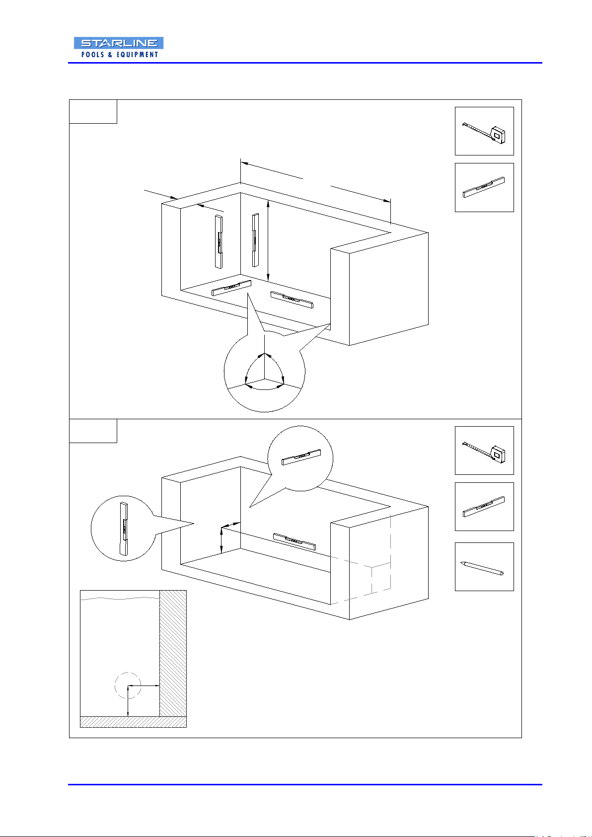
RDBIPBMM.03 17
10. Measuring Pool / messen Becken / inmeten bad
Y
X
YX
?
CHECK
02
90°
W
01
90°
90°
H
B
See datasheet
Siehe Datenblatt
Zie datablad
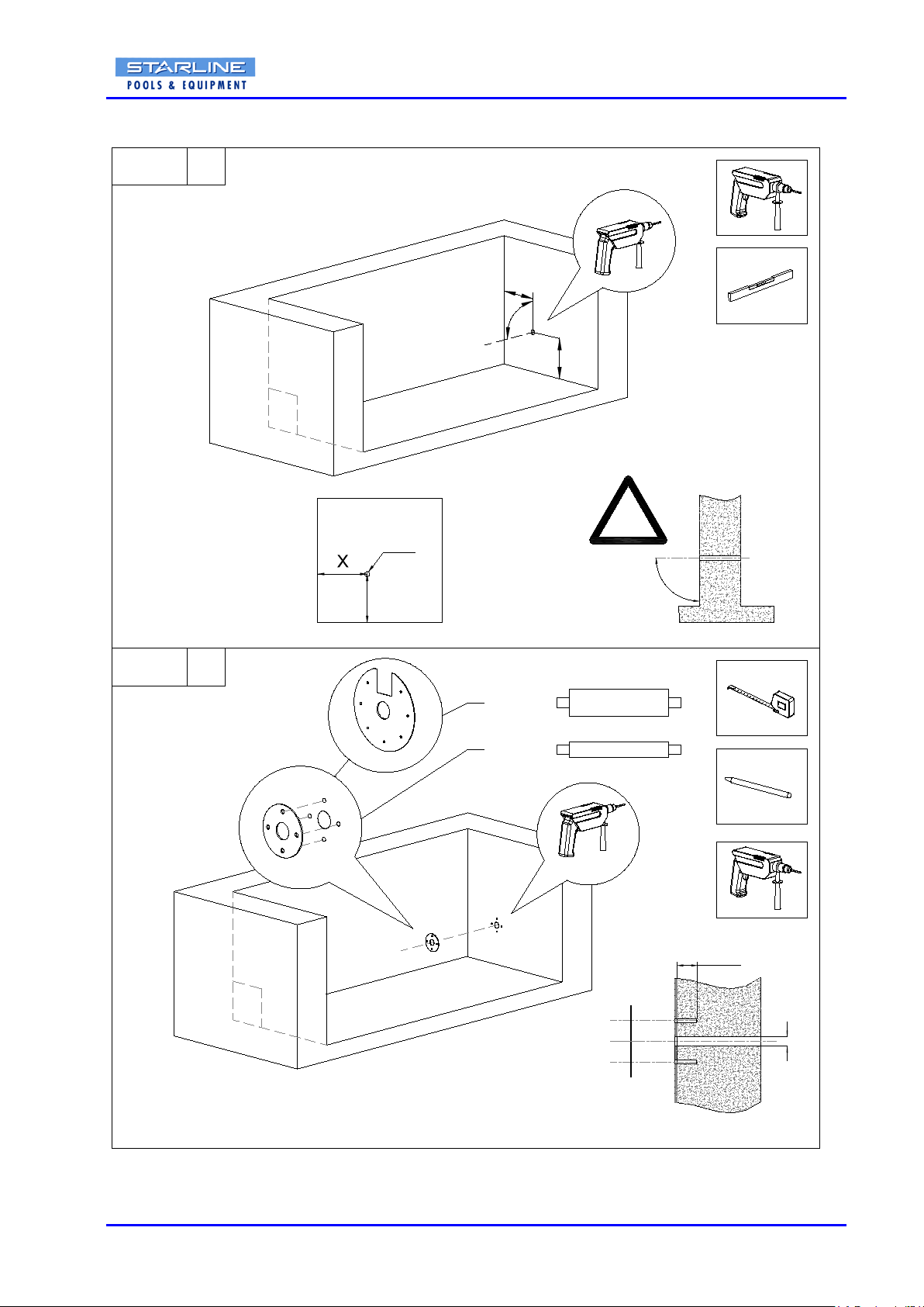
RDBIPBMM.03 18
90°
04
min.90
Ø10
Ø10 (4x)
Y
Y
90°
X
Ø35
Ø35 !
1
03 1
4x
7x
Ø35
Ø323
Ø114,3 - 258
11. Assembling Situation 1 Montage Situation 1 Montage situatie 1
In-roller motor cable through the wall Rohrmotors Anschluss durch der Beckenwand Buismotor kabel door de wand

RDBIPBMM.03 19
M10 x 20 (1x)
S6
05
T40
1
06 1
!
Ø114,3 - 258
Ø323
10 x 80 (4x)
10 x 80 (7x)
T40
Table of contents
Other Starline Lighting Equipment manuals


Popular Lighting Equipment manuals by other brands


Ovation
Ovation PIONEER 200C ZOOM user manual

Elation
Elation ProColor User instructions

Signtex Lighting
Signtex Lighting CAEBB Series Installation instructions & user manual

Alice's Garden
Alice's Garden XMASTL100 manual

LCG
LCG LCG-027A user manual

Williams-Sonoma
Williams-Sonoma Hayes Assembly instructions


