manuals.online logo
Brands
  1. Home
  2. •
  3. Brands
  4. •
  5. Staubli
  6. •
  7. Control Unit
  8. •
  9. Staubli CombiTac direqt User manual

Staubli CombiTac direqt User manual

1 / 24
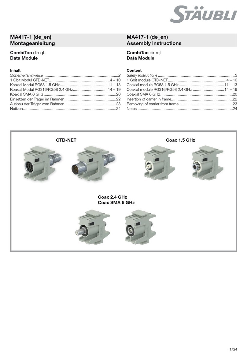
CTD-NET Coax 1.5 GHz
Coax 2.4 GHz
Coax SMA 6 GHz
MA417-1 (pt_en)
Instruções de montagem
Índice
Instruções de segurança �������������������������������������������������������������2
Módulo CTD-NET 1 Gbit......................................................4 – 10
Módulo coaxial RG58 1,5 GHz ..........................................11 – 13
Módulo coaxial RG316/RG58 2,4 GHz ..............................14 – 19
SMA coaxial 6 GHz ...................................................................20
Inserção do suporte na estrutura ...............................................22
Remoção do suporte da estrutura .............................................23
Notas ........................................................................................24
CombiTac direqt
Módulo de dados
MA417-1 (pt_en)
Assembly instructions
CombiTac direqt
Data Module
Content
Safety Instructions �����������������������������������������������������������������������2
1 Gbit module CTD-NET......................................................4 – 10
Coaxial module RG58 1.5 GHz..........................................11 – 13
Coaxial module RG316/RG58 2.4 GHz .............................14 – 19
Coaxial SMA 6 GHz...................................................................20
Insertion of carrier in frame.........................................................22
Removing of carrier from frame..................................................23
Notes ........................................................................................24
2 / 24
Instruções de segurança Safety instructions
Utilize apenas os componentes e ferramentas especificados pela
Stäubli. Em caso de montagem pelo próprio utilizador, respei-
te as instruções de preparação e de montagem aqui descritas,
pois, caso contrário, a Stäubli não pode garantir a segurança ou
a conformidade com os dados técnicos. Não altere o produto de
forma alguma.
Use only the components and tools specified by Stäubli. In case
of self-assembly, do not deviate from the preparation and assem-
bly instructions as stated herein, otherwise Stäubli cannot give
any guarantee as to safety or conformity with the technical data.
Do not modify the product in any way.
Os conectores não fabricados de origem pela Stäubli que po-
dem ser acoplados aos elementos Stäubli e que, em alguns
casos, até são descritos por determinados fabricantes como
"compatíveis com a Stäubli" não cumprem os requisitos de uma
conexão elétrica segura e duradoura e, por razões de segurança,
não podem ser conectados aos elementos Stäubli. Por isso, a
Stäubli não se responsabiliza por qualquer dano resultante do
acoplamento desses conectores (por exemplo, falta de homolo-
gação da Stäubli) com elementos Stäubli.
Connectors not originally manufactured by Stäubli which can be
mated with Stäubli elements and in some cases are even de-
scribed as ”Stäubli-compatible” by certain manufacturers do not
conform to the requirements for safe electrical connection with
long-term stability, and for safety reasons must not be plugged
together with Stäubli elements. Stäubli therefore does not ac-
cept any liability for any damages resulting from mating such
connectors (i.e. lacking Stäubli approval) with Stäubli elements.
A Stäubli Electrical Connectors (Stäubli) não se responsabiliza
por qualquer falha resultante da inobservância destas advertên-
cias.
Stäubli Electrical Connectors (Stäubli) does not accept any
liability in the event of failure to observe these warnings.
IEC 60417-6182
Instalação, conhecimentos eletrotécnicos Installation, electro technical expertise
Os produtos só podem ser montados e instalados por eletricis-
tas qualificados ou pessoas com conhecimentos eletrotécnicos,
respeitando todos os regulamentos de segurança legais aplicá-
veis.
The products may be assembled and installed by electrically
skilled or instructed persons duly observing all applicable safety
regulations.
IEC 60417-6042
Advertência, risco de choque elétrico Caution, risk of electric shock
Trabalhar num estado sem tensão
Ao trabalhar em instalações elétricas, respeite as cinco regras
de segurança.
Depois de identificar as respetivas instalações elétricas, cumprir
os cinco requisitos fundamentais que se seguem pela ordem es-
pecificada, a não ser que existam razões importantes para pro-
ceder de outra forma:
•Desligar completamente;
•Proteger contra uma nova ligação;
•Verificar a ausência da tensão de alimentação;
•Ligar à terra e curto-circuitar;
•Cobrir ou vedar os componentes adjacentes que estão sob
tensão.
Qualquer pessoa envolvida nesta atividade deverá ser um ele-
tricista qualificado ou possuir a devida instrução para tal, caso
contrário, deverá ser supervisionada por uma pessoa com essa
qualificação.
Fonte: EN 50110-1:2013
Work in a de-energized state
Follow the five safety rules, when working on electrical installa-
tions.
After the respective electrical installations have been identified,
the following five essential requirements shall be undertaken in
the specified order unless there are essential reasons for doing
otherwise:
•disconnect completely;
•secure against re-connection;
•verify absence of operating voltage;
•carry out grounding and short-circuiting;
•provide protection against adjacent live parts.
Any person engaged in this work activity shall be electrically
skilled or instructed, or shall be supervised by such a person.
Source: EN 50110-1:2013
A proteção contra choques elétricos também deverá ser verifica-
da nas aplicações finais.
Protection against electric shock shall be checked in the end-use
applications too.
IEC 60417-6070
Não conectar ou desconectar sob carga Do not connect and disconnect under load
A conexão e a desconexão de componentes sob tensão só
são permitidas se a tensão nominal não exceder os 1000 V CA/
1500 V CC.
Para tensões nominais superiores a 1000 V CA/1500 V CC, a
tensão só pode ser aplicada no estado acoplado; a desconexão
sob carga ou a conexão sob tensão não é permitida. O mesmo
se aplica a ligações elétricas muito próximas de ligações de flui-
dos e gás.
Connecting and disconnecting when live is only permitted if the
rated voltage does not exceed AC 1000 V/DC 1500 V .
For rated voltages over AC 1000 V/DC 1500 V, the voltage must
only be applied in mated condition, disconnecting under load
or connecting when live is not permitted. This also applies for
electrical connections in close proximity to fluid and gas con-
nections.
3 / 24
Instruções de segurança Safety instructions
ISO 7000-0434B
Advertência Caution
Sempre que utilizar o conector, este deverá ser previamente
inspecionado relativamente a defeitos externos (especialmente
o isolamento). Se existir alguma dúvida relacionada com a segu-
rança, deverá ser consultado um eletricista ou o conector terá de
ser substituído.
Each time the connector is used, it should previously be inspect-
ed for external defects (particularly the insulation). If there are any
safety concerns, an electrically skilled person must be consulted
or the connector must be replaced.
Proteção IP conforme a 60529:2013 IP protection according to 60529:2013
Os conectores de encaixe não acoplados têm de ser protegidos
da humidade e da sujidade. Os machos e as fêmeas não podem
ser encaixados uns nos outros se estiverem sujos.
Unmated plug connectors must be protected from moisture and
dirt. The male and female parts must not be plugged together
when soiled.
Verificar; controlar Examine; Check
Para indicar uma verificação ou controlo To indicate examination or checking
Sugestão ou dica útil Useful hint or tip
Para obter mais dados técnicos, consulte o catálogo do produto. For further technical data please see the product catalog.
4 / 24
1245
6
3
6542
1
3
Módulo CTD-NET 1 Gbit
Pos. Descrição/Description
1 Suporte do módulo/Module carrier
2 Corpo do macho/Pin body
3 Saliência de retenção/Retaining clip
4 Suporte de contactos/Contact carrier
5 Anel de fixação/Clamp ring
6 Porca/Nut
Pos. Descrição/Description
1 Suporte do módulo/Module carrier
2 Corpo da fêmea/Socket body
3 Saliência de retenção/Retaining clip
4 Suporte de contactos/Contact carrier
5 Anel de fixação/Clamp ring
6 Porca/Nut
Lado fêmea Lado macho
1 Gbit module CTD-NET
Socket side Pin side
5 / 24
1
2
3
4
(fig. 4)
Chave de fenda
Tamanho 2 e 3
(para a reparação/remoção de suportes
da estrutura).
(fig. 3)
Fita adesiva condutora CU para módu-
los de 1 Gbit,
referência 11012526.
(fig. 2)
Ferramenta de extração
CT-NET-AWZ, referência 33.3048
(apenas para fins de reparação).
Nota:
Modo de emprego MA079 em
www.staubli.com/electrical
ou
Alicate de cravação CT-M-CZ
Referência 33.3800
e posicionador MES-CZ,
Referência 18.3801
Nota:
Modo de emprego MA419,
www.staubli.com/electrical
(fig. 1)
Alicate de cravação CTD-M-CZ
Referência 33.3900
e posicionador MES-CZ-CTD1NET,
Referência 33.3913
Ferramentas necessárias Tools required
(ill. 1)
Crimping pliers CTD-M-CZ
Order No. 33.3900
and locator MES-CZ-CTD1NET,
Order No. 33.3913
Note:
Operating instructions MA419,
www.staubli.com/electrical
or
Crimping pliers CT-M-CZ
Order No. 33.3800
and locator MES-CZ,
Order No. 18.3801
Note:
Operating instructions MA079,
www.staubli.com/electrical
(ill. 2)
Extraction tool
CT-NET-AWZ, order No. 33.3048
(For repair purposes only).
(ill. 3)
CU conductive tape for 1 Gbit
moduls, order No. 11012526.
(ill. 4)
Screwdriver
Size 2 and 3
(for repair/removal of carriers from
frame).
6 / 24
6
4,5
5
Tab. 1
Etapas
Steps Cabo 1/Cable 1 Cabo 2/Cable 2
1
18 18
2
33.1 3.2 3.3
4
(fig. 6)
Afaste os fios individuais e descarne-os
em 4,5 mm.
(Tab. 1)
Sem danificar a blindagem, remova cuidadosamente 18 mm do
isolamento exterior do cabo.
•Para cabos do tipo 1, puxe novamente os fios de blindagem
sobre o cabo de isolamento exterior e fixe-os com 2 voltas de
fita adesiva condutora.
•Para cabos do tipo 2, corte o papel de blindagem. Coloque
uma volta de fita adesiva condutora sobre o isolamento exterior
(3.1). Puxe o fio de drenagem sobre a fita adesiva condutora
(3.2) e, por fim, fixe o fio de drenagem com 2 voltas de fita
adesiva condutora (3.3).
(fig. 5)
Enfie a porca Me o anel de fixação Z
no cabo pela sequência indicada.
Diâmetro do cabo:
Mín. 5,5mm
Máx. 7,5mm
Preparação dos cabos Cable preparation
(ill. 5)
Slip nut Mand clamp ring Zin the indi-
cated sequence onto the cable.
Cable diameter:
Min. 5.5mm
Max. 7.5mm
(Tab. 1)
Without damaging the shielding, carefully strip 18 mm of outer
cable insulation.
•For type 1 cable, pull the shield wires back over the outer insu-
lation cable and secure with 2 turns of conductive tape.
•For type 2 cable, cut o the shield paper. Place one turn of
conductive tape over outer insulation (3.1). Pull back the drain
wire over the conductive tape (3.2) and finally secure the drain
wire with 2 turns of conductive tape (3.3).
(ill. 6)
Fan out single wires and strip them to
4.5mm.
7 / 24
7
8
B
S
9
Orifício de observação
(fig. 9)
O encaixe fêmea está identificado com
um B, o encaixe macho está identifica-
do com um S.
Os números dos contactos encontram-
-se na parte de trás.
Os contactos serão introduzidos pela
parte de trás.
Tab. 2
Secção do condutor
Conductor cross section Posição do seletor
Selector position
mm² AWG
0.14 26 1
0.25 24 2
0.34 22 3
0.51) 20 4
0.751) 18 5
1) Máximo de quatro cabos por conector
1) Maximal four wires per connector
(fig. 8)
Ver Tab. 2 para a posição do seletor
de acordo com a secção do condutor.
(contactos de Ø 1 mm, 1,5 mm,
3 mm)
Nota:
O cabo tem de ser visível através do
orifício de observação antes e após
o engaste.
(fig. 7)
Introduza ao máximo o cabo na bucha
de engaste.
Engaste Crimping
(ill. 7)
Insert wire into the crimping sleeve as
far as it will go.
(Ø 1 mm, 1.5 mm, 3 mm contacts)
Note:
Wire must be visible in the sight hole
before and after crimping.
(ill. 8)
See Tab. 2 for selector position
according to conductor cross section.
(ill. 9)
The female insert is marked with a B,
the pin insert is marked with an S.
The contact numbers are on the back
side.
The contacts will be inserted from back
side.
Sight hole
8 / 24
10
Ethernet/Profinet
CAT5
CAT5e
Interbus
Profibus
Ethernet/Profinet
11
Interbus
DO 1
/DO 2
DI 3
/DI 6
COM 4
Profibus
Linha A/
Line A 1
Linha B/
Line B 2
GND 4
Ethernet 100 MBit & Profinet
TX+ 1
TX- 2
RX+ 3
RX- 6
CANbus
Configuração individual de acordo
com as especificações do barramento
Individual configuration according to
BUS specifications
Lado macho Lado fêmea
Atenção
As câmaras de contactos não
utilizadas deverão ser fechadas
com bujões cegos
CT-NET-BS, referência 33.9589
(fig. 11)
Insira os contactos pelo lado numerado
até encaixarem no devido lugar.
Tab. 4
N.º contacto
Contact No.
N.º par
Pair No. Cor Colour
1 1 branco/laranja white/orange
2 1 laranja orange
3 2 branco/verde white/green
4 3 azul blue
5 3 branco/azul white/blue
6 2 verde green
7 4 branco/castanho white/brown
8 4 castanho brown
Ethernet & Profinet até 1 GBit
Configuração com 4 pares T568B
Tab. 3
N.º contacto
Contact No.
N.º par
Pair No. Cor Colour
1 1 branco/verde white/green
2 1 verde green
3 2 branco/laranja white/orange
4 3 azul blue
5 3 branco/azul white/blue
6 2 laranja orange
7 4 branco/castanho white/brown
8 4 castanho brown
Ethernet & Profinet até 1 GBit Confi-
guração com 4 pares T568A
(fig. 10)
(visto do lado da terminação)
Esquema de contactos do suporte de contactos Contact arrangement of the contact carrier
(ill. 10)
(Seen from the termination side)
Ethernet & Profinet up to 1 GBit
configuration with 4 pairs T568A
Ethernet & Profinet up to 1 GBit
configuration with 4 pairs T568B
(ill. 11)
Push the contacts through the number
indicated side until they lock into place.
Attention
Unused contact chambers should
be closed with blind plugs
CT-NET-BS, order No. 33.9589
Pin side Socket side
9 / 24
12
A
13
B
C
D
14
MB
15
M
•Verifique se os contactos estão devidamente introduzidos no
suporte puxando delicadamente o cabo.
Atenção
Após o engaste e a montagem nos suportes de contactos,
e antes da primeira ligação, verifique se as fichas não estão
danificadas (dobradas, partidas, etc.)
Atenção
Aperte a porca apenas manualmente (sem ferramenta).
A quantidade de rosca visível depois de apertar a porca
depende do diâmetro exterior do cabo.
(fig. 15)
•Insira toda a unidade no suporte de contactos.
Certifique-se de que a posição da parte plana está correta.
•Aperte a porca Menquanto segura o cabo para evitar a ro-
tação do mesmo.
Clique
(fig. 14)
•Enfie a porca Mno anel de fixação B.
(fig. 13)
Conecte o anel de fixação Bao suporte de contactos C.
Coloque a peça principal Dsobre a área plana do suporte de
contactos C.
(fig. 12)
Coloque a saliência de retenção Ana ranhura do corpo do ma-
cho e introduza tudo no suporte de contactos.
Um clique percetível assinala uma inserção completa.
Nota:
Consulte as páginas 22 – 23 para saber como inserir e
remover corretamente o suporte na/da estrutura.
Montagem no suporte de contactos
Nota:
Se o porta contactos universal for usado em combinação
com a caixa tamanho 4,com entrada lateral de cabo, por
exemplo CT-CH4-S (Nº 33.2404), favor entrar em contato com
a Stäubli para esclarecimentos.
Assembly in contact carrier
Note:
Please refer to pages 22 – 23 for correct insertion and
removing of carrier in frame.
(ill. 12)
Mount retaining clip Ain the groove of the pin body and push
everything into contact carrier.
A “click” sound is heard once fully inserted.
(ill. 13)
Connect the clamp ring Bto the contact carrier C.
Place the leading part Dover the flat area of the contact
carrier C.
(ill. 14)
•Push nut Mover the clamp ring B.
(ill. 15)
•Insert the whole unit in the contact carrier.
Ensure that the position of the flat part is correct.
•Tighten nut Mwhile holding the cable to avoid any cable rota-
tion.
Attention
Tighten the nut only by hand (without tool). The amount of
thread that is visible after tightening the nut depends on the
outside diameter of the cable.
Attention
After crimping and assembly into the contact carriers, and
before first connection, check that the plugs are not dam-
aged (bent, broken…)
•Check that contacts are securely inserted in the carrier by gen-
tly pulling the cable.
Clic
Note:
If the universal carrier is used in combination with the size4
housing with side cable entry, for example CT-CH4-S (Order
No. 33.2404), please contact us for clarification.
10 / 24
17
CT-NET-AWZ D
16
1
2
3
4
(fig. 17)
•Insira a ferramenta de extração CT-
-NET-AWZ pelo lado da frente no
encaixe do contacto até ouvir um
clique.
•Depois, com o mandril D, retire o
contacto.
Extração de contactos
(fig. 16)
1. Aplique uma força ligeira e contínua
sobre o tubo CT-Net.
2. Use a chave de fenda para pressio-
nar a primeira saliência.
3. Pressione a segunda saliência com a
chave de fenda.
4. Retire o encaixe do contacto
Extração do CTD-NET do su-
porte
Extraction of CTD-NET from
carrier
(ill. 16)
1. Apply a slight continuous force on
the CT-Net tube.
2. Use the screwdriver to press the first
clip.
3. Press the second clip with the
screwdriver.
4. Pull out the contact insert
Extraction of contacts
(ill. 17)
•Insert the extraction tool CT-NET-AWZ
from the front side into the contact
insert until you hear a click.
•Then with the drift Dpush out the
contact.
11 / 24
2
1
2133
1
2
3
(fig. 3)
Ajuste o alicate para descarnar CT-AIWZ/COAX de acordo com
os tamanhos indicados e remova o revestimento do cabo.
Preparação dos cabos
(fig. 2)
Alicate de cravação CT-CZ/COAX
Referência 33.3010
(fig. 1)
Alicate para descarnar CT-AIWZ/COAX
Referência 33.3011
Ferramentas necessárias
Pos. Descrição/Description
1Suporte do módulo/Module carrier
2 Saliência de retenção/Retaining clip
3 Corpo da fêmea/Socket body
Pos. Descrição/Description
1Suporte do módulo/Module carrier
2 Saliência de retenção/Retaining clip
3 Corpo da fêmea/Socket body
Lado macho
Lado fêmea
RG58 coaxial 1,5 GHz
Coaxial RG58 1.5 GHz
Pin sideSocket side
(ill. 1)
Insulation stripper CT-AIWZ/COAX
Order No. 33.3011
(ill. 2)
Crimping pliers CT-CZ/COAX
Order No. 33.3010
Cable preparation
(ill. 3)
Adjust the insulation stripper CT-AIWZ/COAX according to the
indicated dimensions and strip the cable.
Tools required
12 / 24
5
6
7
8
9
4
A
C
Nota:
Consulte as páginas 22 – 23 para saber como inserir e
remover corretamente o suporte na/da estrutura.
(fig. 9)
•Fixe a bucha de engaste na devida
posição RG58 = 5,41 mm
ou RG59 = 6,48 mm.
(fig. 8)
•Passe a bucha de engaste sobre a
blindagem.
(fig. 7)
•Puxe os fios de blindagem sobre a
caixa de cravação.
(fig. 6)
•Insira o cabo na caixa de cravação
até que o contacto encaixe no isola-
mento interior.
(fig. 5)
•Insira a bucha de engaste C no cabo.
Nota:
O cabo tem de ser visível através
do orifício de observação antes e
após o engaste.
(fig. 4)
•Insira o condutor individual na bucha
de engaste do contacto, no sentido
axial, até ao batente.
•Coloque-o no alicate de cravação.
•Execute o processo de cravação.
Nota:
Os procedimentos de montagem
para fêmeas e machos são idênticos.
Montagem de cabos Cable assembly
Note:
The assembly procedures for
sockets and plugs are identical.
(ill. 4)
•Insert single conductor in axial direc-
tion into crimping sleeve of contact as
far as it will go.
•Place in crimping pliers.
•Perform crimping process.
Note:
Wire must be visible in the sight
hole before and after crimping.
(ill. 5)
•Slip crimp sleeve C onto the cable.
(ill. 6)
•Insert the cable into the crimp hous-
ing until the contact engages in the
inner insulator.
(ill. 7)
•Push the shield wires over the crimp
housing.
(ill. 8)
•Slip the crimp sleeve over the shield.
(ill. 9)
•Crimp the crimp sleeve in the re-
quired position RG58 = 5.41 mm
or RG59 = 6.48 mm.
Note:
Please refer to pages 22 – 23 for correct insertion and
removing of carrier in frame.
13 / 24
A
1
2
3
4
10
11
Clique
(fig. 11)
1. Aplique uma força ligeira e contínua
sobre o tubo CT-Net.
2. Use a chave de fenda para pressio-
nar a primeira saliência.
3. Pressione a segunda saliência com a
chave de fenda.
4. Retire o encaixe do contacto
Extração de contactos
(fig. 10)
Coloque a saliência de retenção Ano
corpo do macho e introduza tudo no
suporte de contactos.
Um clique percetível assinala uma inser-
ção completa.
(ill. 10)
Mount retaining clip Aon pin body and
push everything into contact carrier.
A “click” sound is heard once fully
inserted.
Extraction of contacts
(ill. 11)
1. Apply a slight continuous force on
the CT-Net tube.
2. Use the screwdriver to press the first
clip.
3. Press the second clip with the
screwdriver.
4. Pull out the contact insert
Clic
14 / 24
1
3456789 2
13456789 2
Pos. Descrição/Description
1 Fêmea/Socket
2 Saliência de retenção/Retaining clip
3 Isolamento/Insulator
4 Fêmea/Socket
5 Distanciador/Spacer
6 Bucha/Sleeve
7 Borracha/Rubber
8 Anel/Ring
9 Porca/Nut
Referência
Order No.
Tipo
Type
33.0230 CT-B-COAX-RG316/U
33.0231 CT-B-COAX-RG58
Lado fêmea
Pos. Descrição/Description
1 Macho/Pin
2 Saliência de retenção/Retaining clip
3 Isolamento/Insulator
4 Macho/Pin
5 Distanciador/Spacer
6 Bucha/Sleeve
7 Borracha/Rubber
8 Anel/Ring
9 Porca/Nut
Referência
Order No.
Tipo
Type
33.0630 CT-S-COAX-RG316/U
33.0631 CT-S-COAX-RG58
Lado macho
RG316/RG58 coaxial 2,4 GHz
Coaxial RG316/RG58 2.4 GHz
Pin side
Socket side
15 / 24
3
4
5
2
1
6
(7)
(6)
(8)
Porca
Anel
Borracha
Cabo
(fig. 6)
Coloque primeiro as peças individuais (porca 8, anel 7e borracha
6) no cabo conforme ilustrado. A borracha encontra-se no lado
mais próximo da extremidade do cabo.
Nota:
O procedimento de montagem do lado do macho e do lado da fêmea é idêntico!
Preparação dos cabos
(fig. 5)
Alicate de corte lateral
(fig. 4)
Chave de fenda tamanho 0
Chave de bocas para cravação:
9 mm, 10 mm
Chave de bocas para SMA:
8 mm, 11 mm
(fig. 3)
Alicate para descarnar.
Utilize um alicate para descarnar ade-
quado para RG58, RG316/U, RG174,
RG188.
(fig. 2)
Posicionador MES-CZ-CTD0,6-COAX-RG,
Referência 33.3914
Nota:
Modo de emprego MA419
www.staubli.com/electrical
(fig. 1)
Alicate de cravação CTD-M-CZ,
Referência 33.3900
Ferramentas necessárias Tools required
(ill. 1)
Crimping pliers CTD-M-CZ,
Order No. 33.3900
Note:
Operating instructions MA419
www.staubli.com/electrical
(ill. 2)
Locator MES-CZ-CTD0,6-COAX-RG,
Order no. 33.3914
(ill. 3)
Insulation stripper.
Use a suitable insulation stripper for
RG58, RG316/U, RG174, RG188.
(ill. 4)
Screwdriver size 0
Open-end wrench crimp: 9 mm, 10 mm
Open-end wrench SMA: 8 mm, 11 mm
(ill. 5)
Side cutting pliers
Cable preparation
Note:
Pin and socket side assembly procedure is identical!
(ill. 6)
First place single parts (nut 8, ring 7and rubber 6) on the cable as
shown. The rubber is on the side closest to the cable end.
Cable
Rubber
Ring
Nut
16 / 24
7
10 0/-0.2 (mm)
8
(6)
7 0/-0.2 (mm)
9
Isolamento
dielétrico
(fig. 9)
Remova o isolamento dielétrico em 7 0/-0,2 mm.
Preparação do condutor interior
Borracha
Malha de blindagem
(fig. 8)
Afaste a malha de blindagem. Mova a borracha 6para a frente
até que esta fique alinhada com o revestimento. Coloque a malha
de blindagem em volta da borracha.
Preparação da malha de blindagem
Atenção
Não danifique a malha de blindagem.
Revestimento exterior
Malha
de blindagem
(fig. 7)
Remova o isolamento (revestimento exterior) em 10 0/-0,2 mm.
Isto aplica-se a todos os tipos de cabo.
(ill. 7)
Strip the insulator (outer sheath) to 10 0/-0.2 mm. This applies to
all cable types.
Shielding braid Outer sheath
Attention
Do not damage the shielding braid.
Shielding braid preparation
(ill. 8)
Fan out shielding braid. Move rubber 6forward until it is flush with
the sheath. Place shielding braid around the rubber.
Shielding braid
Rubber
Inner conductor preparation
(ill. 9)
Strip the dielectric insulator to 7 0/-0.2 mm.
Dielectric insulator
17 / 24
10
(5)
11
(3)
(4)
12
Área de engaste
Orifício de observação
Isolamento dielétrico
Malha de blindagem
Bucha
Nota (fig. 12):
O cabo tem de ser visível através do orifício de observação
antes e após o processo de cravação.
(fig. 11)
Passe primeiro o distanciador 4sobre o condutor interior até ao
isolamento dielétrico. Depois, coloque o macho ou a fêmea 3so-
bre o condutor interior e empurre-o para trás até chegar ao anel.
Por fim, use o alicate de cravação CT-MC-Z (33.3380) para efe-
tuar o engaste conforme indicado no modo de emprego MA079.
Use o posicionador MES-CZ-CT0,6-COAX-RG (18.3808) para um
posicionamento de cravação correto.
Para cabos RG58, ajuste a posição do alicate de cravação para
“SEL No. 4” e, para cabos RG174, RG188, RG316/U, para “SEL
No.2”.
Distanciador
Condutor interior
Macho ou fêmea
Isolamento dielétrico
Terminação do condutor interior
(fig. 10)
Passe a bucha 5sobre o isolamento dielétrico até tocar na malha
de blindagem.
Montagem da bucha de blindagem Shielding sleeve assembly
(ill. 10)
Push the sleeve 5over the dielectric insulator until it touches the
shielding braid.
Inner conductor termination
Dielectric insulator
Pin or socket
Inner conductor
Spacer
(ill. 11)
First push the spacer 4over the inner conductor until the dielec-
tricum insulator. Then place the pin or socket 3over the inner
conductor and push back until it reaches the ring.
Finally, use the crimping pliers CT-MC-Z (33.3380) to crimp ac-
cording to MA079 operating instructions.
Use locator MES-CZ-CT0,6-COAX-RG (18.3808) for correct
crimp positioning.
For RG58 cables adjust crimping pliers position to “SEL No. 4”,
and “SEL No.2” for RG174, RG188, RG316/U cables.
Note (ill. 12):
The conductor must be visible in the sight hole, before and
after the crimping process.
Sleeve
Shielding braid Dielectric insulator
Sight hole
Crimp area
18 / 24
13
14
(2) (3) (4)
15
(2)
(1)
(8) SW, A/F 10 mm
SW, A/F 9 mm
max. 1 mm
Porca
Isolamento
Macho/fêmea
(fig. 15)
Coloque o macho/fêmea 1sobre o isolamento 2e enrosque-o na
porca 8. Depois de enroscado, é permitida uma folga máxima de
1 mm entre o macho/fêmea e a porca.
(fig. 14)
Passe o isolamento 2sobre o macho ou fêmea 3até ao distan-
ciador 4.
DistanciadorMacho ou fêmea
Isolamento
(fig. 13)
Use o alicate de corte lateral para cortar quaisquer fios trançados
que se projetem para além da bucha. Para evitar o contacto entre
os fios trançados e o condutor interior, os fios trançados não
podem sair para fora da bucha.
Os fios trançados não deverão projetar-se para além
da bucha.
Fios trançados
Montagem do isolamento do macho/fêmea e do
macho/fêmea
Assembly of insulator and pin/socket
Braid wires
Braid wires should not project beyond the sleeve.
(ill. 13)
Use the side cutting pliers to cut o any braid wires that project
beyond the sleeve. To prevent contact between braid wires and
inner conductor, braid wires must not project beyond the sleeve.
Insulator Pin or socket Spacer
(ill. 14)
Push the insulator 2over the pin or socket 3and onto the spacer
4.
(ill. 15)
Place the pin/socket 1over the insulator 2, and screw it onto
the nut 8. When screwed, a maximum 1 mm gap is permitted
between the pin/socket and nut.
Pin/socket
Insulator
Nut
19 / 24
16
(fig. 16)
Insira os contactos e bloqueie-os com a saliência de retenção.
Montagem de contactos macho e fêmea engasta-
dos no suporte
Nota:
Consulte as páginas 22 – 23 para saber como inserir e
remover corretamente o suporte na/da estrutura.
Note:
Please refer to pages 22 – 23 for correct insertion and
removing of carrier in frame.
Assembly of crimped pin and socket contacts in
carrier
(ill. 16)
Insert contacts and lock with the retaining clip.
20 / 24
17 18
SW, A/F 8 mm
SW, A/F 11 mm
19
(fig. 19)
Insira os contactos e bloqueie-os com a saliência de retenção.
O sextavado evita que os contactos SMA rodem.
Nota:
Consulte as páginas 22 – 23 para saber como inserir e
remover corretamente o suporte na/da estrutura.
Montagem de contactos macho e fêmea SMA no
suporte
(fig. 17 - 18)
Enrosque o seu conector SMA no contacto CombiTac SMA.
Binário de aperto máx. de 1 Nm.
Montagem com terminação SMA
SMA coaxial 6 GHz
Coaxial SMA 6 GHz
Assembly with SMA termination
(ill. 17 - 18)
Screw your SMA connector onto the CombiTac SMA contact.
Max. tightening torque 1 N m.
Assembly of SMA pin and socket contacts in
carrier
Note:
Please refer to pages 22 – 23 for correct insertion and
removing of carrier in frame.
(ill. 19)
Insert contacts and lock with the retaining clip.
The hexagon prevents the SMA contacts from rotating.

Other manuals for CombiTac direqt

4

This manual suits for next models

4

Other Staubli Control Unit manuals

Staubli CombiTac uniq CT-E1,5-4/HV-B User manual

Staubli

Staubli CombiTac uniq CT-E1,5-4/HV-B User manual

Staubli CombiTac direqt User manual

Staubli

Staubli CombiTac direqt User manual

Staubli CombiTac 10Gbit Series User manual

Staubli

Staubli CombiTac 10Gbit Series User manual

Staubli MA417-1 User manual

Staubli

Staubli MA417-1 User manual

Staubli MA010 User manual

Staubli

Staubli MA010 User manual

Staubli CombiTac direqt CTD-NET User manual

Staubli

Staubli CombiTac direqt CTD-NET User manual

Staubli CombiTac uniq CT-10GBIT-RJ45/S User manual

Staubli

Staubli CombiTac uniq CT-10GBIT-RJ45/S User manual

Staubli CombiTac uniq CT-E1,5-4/HV-B User manual

Staubli

Staubli CombiTac uniq CT-E1,5-4/HV-B User manual

Popular Control Unit manuals by other brands

CLA-VAL 39A owner's manual

CLA-VAL

CLA-VAL 39A owner's manual

Visual Productions IOCORE manual

Visual Productions

Visual Productions IOCORE manual

Eaton MMX-COM-PC Instruction leaflet

Eaton

Eaton MMX-COM-PC Instruction leaflet

Erica Synths Black Series manual

Erica Synths

Erica Synths Black Series manual

Honeywell BA295STN-11/2C Installation instruction

Honeywell

Honeywell BA295STN-11/2C Installation instruction

Agilent Technologies G4239C instructions

Agilent Technologies

Agilent Technologies G4239C instructions

Panasonic SF-C21 instruction manual

Panasonic

Panasonic SF-C21 instruction manual

Skylab SKW75 user manual

Skylab

Skylab SKW75 user manual

SunMaxx Solar ADVANCED SOLAR CONTROLLER user guide

SunMaxx Solar

SunMaxx Solar ADVANCED SOLAR CONTROLLER user guide

Rockwell Automation Allen-Bradley ControlLogix B Series user manual

Rockwell Automation

Rockwell Automation Allen-Bradley ControlLogix B Series user manual

Siemens FDCI723 manual

Siemens

Siemens FDCI723 manual

Maxsys PC4108A Installation instructions manual

Maxsys

Maxsys PC4108A Installation instructions manual

Eaton NH00 installation instructions

Eaton

Eaton NH00 installation instructions

Rain Bird CP Troubleshooting and maintenance guide

Rain Bird

Rain Bird CP Troubleshooting and maintenance guide

Elster Kromschroder S11T operating instructions

Elster

Elster Kromschroder S11T operating instructions

Toshiba T300MVi MEDIUM VOLTAGE Specifications

Toshiba

Toshiba T300MVi MEDIUM VOLTAGE Specifications

Advantech EWM-W179M201E user manual

Advantech

Advantech EWM-W179M201E user manual

Joy-it Talking-Pi manual

Joy-it

Joy-it Talking-Pi manual

manuals.online logo
manuals.online logoBrands
  • About & Mission
  • Contact us
  • Privacy Policy
  • Terms and Conditions

Copyright 2025 Manuals.Online. All Rights Reserved.