Staubli MGK Series User manual

1/24
1 3
2
4 5 6
Gr.3 = M25x1.5 / M32x1.5
Gr.4 = M32x1.5 / M40x1.5 / M50x1.5
Gr.1 = M20x1.5
Gr.2 = M25x1.5
7
WST90-...WST-TS
MA203 (de_en)
Montageanleitung
MA203 (de_en)
Assembly instructions
DuraDock multi – MGK…, MGS…, MGA...
[Größen 1-4]
Gehäuse für runde, mehrpolige Steckverbinder
DuraDock multi – MGK…, MGS…, MGA...
[sizes 1-4]
Housings for circular, multipole electrical inserts
Inhalt
Sicherheitshinweise ������������������������������������������������������������������2-3
Erforderliches Werkzeug �������������������������������������������������������������� 4
Montage der Steckverbinder�������������������������������������������������������� 4
Bohrplan�������������������������������������������������������������������������������������� 5
Einbausituationen Gr� 1 MGK/MGS ������������������������������������������7-8
Variante geschirmt / isoliert 90° Abgang �������������������������������������� 9
Einbausituationen Gr� 1 / 90°����������������������������������������������������� 10
Giga1-IS���-M12X gerade/gewinkelt / Giga10-��� �������������������11-13
Einbausituationen Gr�2 MGK/MGS ���������������������������������������15-16
Einbausituationen Gr�3 MGK/MGS ���������������������������������������17-18
Formteilmontage������������������������������������������������������������������������ 19
Content
Safety Instructions ��������������������������������������������������������������������2-3
Tools required������������������������������������������������������������������������������ 4
Assembly of connector���������������������������������������������������������������� 4
Drilling plan���������������������������������������������������������������������������������� 5
Installation situations size 1 MGK/MGS�������������������������������������7-8
Shielded/insulated right-angled outlet version ������������������������������ 9
Installation situations Size 1 / 90°����������������������������������������������� 10
Giga1-IS���-M12X straight/angled / Giga10-��� ����������������������11-13
Installation situations Gr�2 MGK/MGS�����������������������������������15-16
Installation situations Gr�3 MGK/MGS�����������������������������������17-18
Assembly of form shroud����������������������������������������������������������� 19
1. Stiftgehäuse-Vorderteil
2. Buchsengehäuse-Vorderteil
3. Sicherungsring
4. Zwischenring*
5. O-Ring
6. Gehäuserückteil
7. Passkerbstift
1. Pin housing front section
2. Socket housing front section
3. Retaining ring
4. Spacer ring*
5. O-Ring
6. Housing back section
7. Grooved pin
Hinweis:
in Kombination mit 18�0305 und 18�0304 (MGK3V���10-14 +
MGK3R-WST)�
Note:
in combination with 18�0305 and 18�0304 (MGK3V���10-14 +
MGK3R-WST)�

2/24
Sicherheitshinweise Safety instructions
Die Montage und Installation der Produkte darf ausschließlich
durch Elektrofachkräfte oder elektrotechnisch unterwiesene Per-
sonen unter Berücksichtigung aller anwendbaren gesetzlichen
Sicherheitsbestimmungen und Regelungen erfolgen�
Stäubli Electrical Connectors (Stäubli) lehnt jegliche Haftung infol-
ge Nichteinhaltung dieser Warnhinweise ab�
The products may be assembled and installed by electrically
skilled or instructed persons duly observing all applicable safety
regulations�
Stäubli Electrical Connectors (Stäubli) does not accept any liabil-
ity in the event of failure to observe these warnings�
Benutzen Sie nur die von Stäubli angegebenen Einzelteile und
Werkzeuge� Weichen Sie nicht von den hier beschriebenen
Vorgängen zur Vorbereitung und Montage ab, da sonst bei der
Selbstkonfektionierung weder die Sicherheit noch die Einhaltung
der technischen Daten gewährleistet ist� Ändern Sie das Produkt
in keiner Weise ab�
Use only the components and tools specified by Stäubli� In case
of self-assembly, do not deviate from the preparation and assem-
bly instructions as stated herein, otherwise Stäubli cannot give
any guarantee as to safety or conformity with the technical data�
Do not modify the product in any way�
Nicht von Stäubli hergestellte Steckverbindungen, die mit Stäubli-
Elementen steckbar sind und von einigen Herstellern manchmal
auch als „Stäubli-kompatibel“ bezeichnet werden, entsprechen
nicht den Anforderungen für eine sichere, langzeitstabile elekt-
rische Verbindung und dürfen aus Sicherheitsgründen nicht mit
Stäubli-Elementen gesteckt werden� Stäubli übernimmt daher
keine Haftung, falls diese von Stäubli nicht freigegebenen Steck-
verbindungen mit Stäubli-Elementen gesteckt werden und des-
halb Schäden entstehen�
Connectors not originally manufactured by Stäubli which can be
mated with Stäubli elements and in some cases are even de-
scribed as ”Stäubli-compatible” by certain manufacturers do not
conform to the requirements for safe electrical connection with
long-term stability, and for safety reasons must not be plugged
together with Stäubli elements� Stäubli therefore does not ac-
cept any liability for any damages resulting from mating such
connectors (i�e� lacking Stäubli approval) with Stäubli elements�
Caution, risk of electric shock
(IEC 60417-6042)
Arbeiten im spannungsfreien Zustand
Die fünf Sicherheitsregeln sind bei Arbeiten an elektrischen Instal-
lationen zu beachten�
Nachdem die betroenen Anlagenteile festgelegt sind, müssen
die folgenden fünf wesentlichen Anforderungen in der angege-
benen Reihenfolge eingehalten werden, sofern es nicht wichtige
Gründe gibt, davon abzuweichen:
– Freischalten;
– gegen Wiedereinschalten sichern;
– Spannungsfreiheit feststellen;
– Erden und kurzschließen;
– benachbarte, unter Spannung stehende Teile abdecken oder
abschranken�
Alle an der Arbeit beteiligten Personen müssen Elektrofachkräf-
te oder elektrotechnisch unterwiesene Personen sein oder unter
Aufsichtsführung einer solchen Person stehen�
Quelle: EN 50110-1:2013 (DIN EN 50110-1, VDE 0105-1)
Work in a de-energized state
Follow the five safety rules, when working on electrical installa-
tions�
After the respective electrical installations have been identified,
the following five essential requirements shall be undertaken in
the specified order unless there are essential reasons for doing
otherwise:
- disconnect completely;
- secure against re-connection;
- verify absence of operating voltage;
- carry out earthing and short-circuiting;
- provide protection against adjacent live parts�
Any person engaged in this work activity shall be electrically
skilled or instructed, or shall be supervised by such a person�
Source: EN 50110-1:2013
Der Schutz gegen elektrischen Schlag ist auch in den Endan-
wendungen zu prüfen�
Protection against electric shock shall be checked in the end-use
applications too�
Do not disconnect under load
(IEC 60417-6070)
Das Stecken und Trennen unter Spannung ist zulässig� Plugging and unplugging when live is permitted�

3/24
Sicherheitshinweise Safety instructions
Caution
(ISO 7000-0434B)
Vor jedem Gebrauch ist visuell zu prüfen, ob keine äußeren Män-
gel vorhanden sind (besonders an der Isolation)� Wenn Zweifel
bezüglich der Sicherheit bestehen, muss ein Fachmann hinzuge-
zogen oder der Steckverbinder ausgetauscht werden�
Each time the connector is used, it should previously be
inspected for external defects (particularly the insulation)� If there
are any doubts as to its safety, a specialist must be consulted or
the connector must be replaced�
Die Steckverbinder sind wasserdicht gemäß der für das jeweilige
Produkt angegebenen IP-Schutzart�
The plug connectors are watertight in accordance with the
product specific IP protection class�
Nicht gesteckte Steckverbinder sind vor Feuchtigkeit und
Schmutz zu schützen� Die Steckverbinder dürfen nicht in ver-
schmutztem Zustand miteinander gesteckt werden�
Unmated plug connectors must be protected from moisture and
dirt� The male and female parts must not be plugged together
when soiled�
Metallgehäuse, geschirmt
Bei Spannung > 60 V DC oder > 30 V AC, ist das Gehäuse in die
Schutzmaßnahme (PE) mit einzubeziehen�
Bei Verwendung von EMV-Verschraubungen kann das Gehäuse
auch zur Schirmung verwendet werden� Gegebenenfalls muss
beim Einbau eine Isolierung zur Montageplatte erfolgen�
Pin and socket housing shielded
For voltages > 60 V DC or > 30 V AC, the housing must be
connected to earth (ground/PE)� If EMC cable glands are used,
the housing can also be used for shielding purposes� It may be
necessary to insulate it from the mounting panel/plate�
Nützlicher Hinweis oder Tipp
Useful hint or tip
Weitere technische Daten entnehmen Sie bitte dem Produktka-
talog�
For further technical data please see the product catalog�

4/24
1
2
13
2
6
78 9
54
4
3
Erforderliches Werkzeug Tools required
(ill. 1)
Sechskantschlüssel SW3 + SW4�
(ill. 1)
Allen key A/F 3 mm+ 4 mm�
(ill. 2)
Heißluftgebläse 2500W
(nur für Gehäuse Gr� 3)
(ill. 2)
Hot air blower 2500W
(Only for housing size 3)�
(ill. 3)
Sicherungsringzange
(ill. 3)
Retaining ring pliers
1. Stift-Gehäusevorderteil
2. Buchsen-Gehäusevorderteil
3. Sicherungsring
4. Zwischenring
5. O-Ring
6. Stiftkontaktträger bestückt
7. Buchsenkontaktträger bestückt
8. Gehäuserückteil
9. Verschlussschraube
1. Pin housing front section
2. Socket housing front section
3. Retaining ring
4. Spacer ring
5. O-Ring
6. Assembled pin carrier
7. Assembled socket carrier
8. Housing back section
9. Closure screw
(ill. 4)
Konfektionierter Kontaktträger (6 bzw� 7) in Gehäusevorderteil
(1 bzw� 2) einsetzen, dabei auf Führungsnut achten� Gehäuse-
rückteil (8) und O-Ring (5) mit Imbusschrauben auf Gehäusevor-
derteil (1 bzw� 2) schrauben� Zwischenring (4) nur bei Stiftgehäuse
Gr� 3 einsetzen�
Kabelverschraubung anbringen. Freie Kabelverschrau-
bung-Önung im Gehäuserückteil (8) mit Verschluss-
schraube (9) schließen.
(ill. 4)
Insert the fully assembled contact carrier (6 or 7) in the front
section of the housing (1 or 2), observing position of alignement
groove� Install O-Ring (5) and screw housing back section (8) to
front section (1 or 2) with all screws; only in the case of size 3 pin
housing, it is also necessary to install spacer ring (4)� Attach the
cable gland�
Close o the unused cable gland tapped hole in the
housing back section (8) with a closure screw (9).
Achtung
Außer bei isolierte, geschirmte (-IS) Gehäuse, gehören Kabel-
verschraubungen nicht zum Stäubli Lieferumfang� Bei Bedarf
sind M20, M25, M323 und M50 Kabelverschraubungen aus
Polyamid (PA) bei Stäubli erhältlich�
Attention
Cable glands are not included in the Stäubli scope of delivery
except with insulated, shielded (-IS) housing� The M20, M25,
M323, and M50 polyamide (PA) cable glands are also avail-
able if necessary�
Hinweis:
Bei 90° Leitungsabgang ist Radialversatz der Leitung jeweils
um 90° durch Drehen des Gehäuserückteils möglich�
Note:
With a right-angle cable lead-in, the cable can be set at 90°
intervals by turning the back section of the housing�
Montage der Steckverbinder Assembly of connector

5/24
MGK1...
MGS1...-IS
MGS1...-S
MGK2...
MGS2...-IS
MGK3... MGS3...-IS
5
Bohrplan Drilling plan
Bohrplan für Montageplatten� Ansicht Vorderseite Stiftgehäuse�
Passkerbstifte gehören zum Gehäuse-Lieferumfang�
Drilling plan for mounting plates� View from front of pin housing�
Grooved pins are included in the delivery of the housing�
MGK4-... Stiftgehäuse
MGK4-... pin housing
MGK4-... Buchsengehäuse
MGK4-... socket housing

6/24
Ø 6. 6+
D
B
0. 1
0
7
8
9
6
(ill. 6)
Giga10-��� 8-polig
(ill. 6)
Giga10-��� 8 pole
(ill. 7)
Spezial Gehäuse
(ill. 7)
Special housing
Montagebohrungen
Assembly holes
Größe
Size
Stiftseite / Buchsenseite
Pin side / Socket side
Winkel
Angle
Spez.- Gehäuse
Spec.-housing
DE8 A± 0,05 d1 d2 αDE8 B±0,05
1
(MGK/MGS...) 28 34 2,1H7 3,1H9 25 28 19
2
(MGK/MGS...) 38 46 3,1H9 4,1H10 30 38 24
3
(MGK...
MGS...)
52
56
60
63
3,1H9
3,1H9
4,1H10
4,1H10
30
30
52 31
4 72 80 3,1H9 4,1H10 33
Einbau der Steckverbinder nach
Bohplan
Connector installation according to
drilling plan
Passkerbstift Grooved pin
(ill. 8 – ill. 9)
Montageplatten gemäß Bohrplan
ausführen� Passkerbstift einsetzen� Ge-
häuse in Montageplatte einsetzen und
mit Sicherungsring (3) befestigen� Das
Gehäuse muss leicht schwimmend in
der Montageplatte gelagert sein�
(ill. 8 – ill. 9)
Prepare mounting plate with holes for
housing and positioning pins according
to drilling plan� Install the grooved pins�
Insert housing in mounting plate and
fasten with retaining ring (3)� Housing
should fit rather loosely in the mounting
plate�
Größe
Size
MGK1 / MGS1 MGK2 MGS2 MGK3 MGS3 MGK4
Buchse / Stift
Socket / Pin
Buchse / Stift
Socket / Pin
Buchse / Stift
Socket / Pin
Buchse / Stift
Socket / Pin
Buchse / Stift
Socket / Pin
Buchse / Stift
Socket / Pin
Stiftüberstand L (mm) / Pin position L (mm)
Plattenabstand
Plate spacing
37 mm
4 / 4 4 / 4 4 / 4 4 / 4 4 / 4 4 / 6
Plattenabstand
Plate spacing
13 mm
14 / 14 18 / 12 16 / 12 18 / 12 18 / 12 -

7/24
10
11
Einbausituationen Installation situations
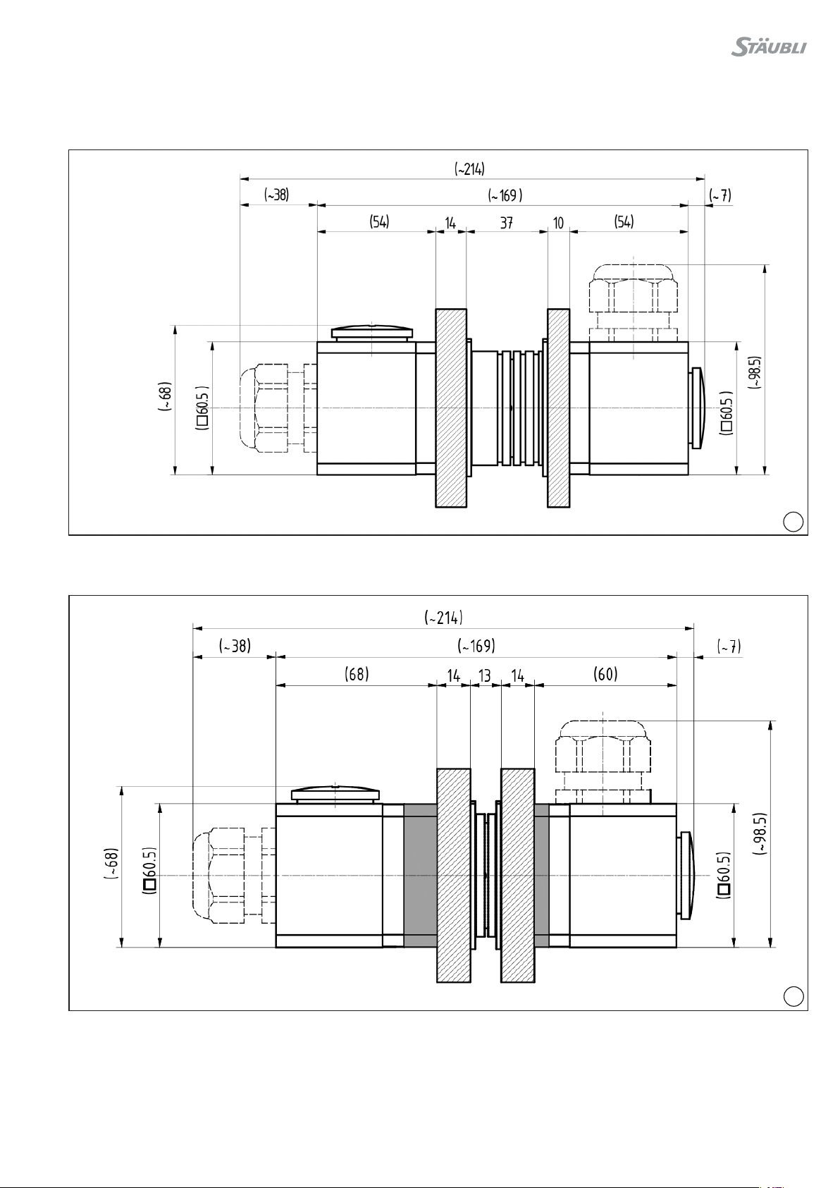
(ill. 10)
Gehäuse Gr� 1 / MGK���
Plattenabstand 37 mm
(ill. 10)
Housing Gr� 1 / MGK���
Plate spacing 37 mm
(ill. 11)
Gehäuse Gr� 1 / MGK���
Plattenabstand 13 mm
(ill. 11)
Housing Gr� 1 / MGK���
Plate spacing 13 mm

8/24
13
12
(ill. 12)
Gehäuse Gr� 1 / MGS���-IS
Plattenabstand 37 mm
(ill. 12)
Housing Gr� 1 / MGS���-IS
Plate spacing 37 mm
(ill. 13)
Gehäuse Gr� 1 / MGS���-IS
Plattenabstand 13 mm
(ill. 13)
Housing Gr� 1 / MGS���-IS
Plate spacing 13 mm

9/24
14
Variante geschirmt / isoliert, 90° Abgang Shielded/insulated right-angled outlet version
gilt nur für Gehäuse Gr� 1 only valid for size 1 housing
1. Stiftgehäuse 1S-Vorderteil
2. Buchsengehäuse 1S-Vorderteil
3. Sicherungsring
4. Stiftkontaktträger bestückt
5. Buchsenkontaktträger bestückt
6. MULTILAM (Schirmung)
7. O-Ring
8. Kontaktteil
9. Isolationsgehäuse
10. Zylinderschraube mit Innensechskant (M3x35)
11. Abdeckhülse
12. EMV-Kabelverschraubung
1. Pin housing, 1S front section
2. Socket housing, 1S front section
3. Retaining ring
4. Assembled pin carrier
5. Assembled socket carrier
6. MULTILAM (shielding)
7. O-ring
8. Contact part
9. Insulating housing
10. Hexagon socket head cap screw with internal hex (M3x35)
11. Cover sleeve
12. EMV cable gland
(ill. 14)
■Konfektionierter Kontaktträger (4 bzw� 5) in Gehäusevorderteil
(1 bzw� 2) einsetzten, dabei auf die Führungsnut achten�
■Das Mehrpolkabel durch die 90° Umlenkung im Kontaktteil (8)
einführen�
■Die Kabelverschraubung (12) und die Abdeckhülse (11) auf das
Mehrpolkabel auädeln�
■Danach Kontaktteil (8) mit bereits vormontierter MULTILAM (6)
und O-Ring (7) ebenfalls in das Gehäusevorderteil (1 bzw� 2) ein-
stecken�
■Die Kabelverschraubung (12) in das Kontaktteil (8) einschrauben
und mit 6Nm anziehen�
■Das Mehrpolkabel in der Kabelverschraubung (12) mit 6Nm an-
ziehen�
■Vormontierten Komponenten in das Isolationsgehäuse (9) ein-
schieben und mit den 4 St� Zylinderschrauben M3x35 (10) fest-
schrauben�
■Die 4 St� Zylinderschrauben M3x35 (10) werden mit max� 1Nm
angezogen�
■Zuletzt wird die Abdeckhülse (11) an das Isolationsgehäuse (9)
leicht handfest angeschraubt�
(ill. 14)
■Insert the fully assembled contact carrier (4 or 5) into the front
part of the housing (1 or 2), observe the position of the alignment
groove�
■Insert the multipole cable into the contact part (8) through the
right-angled reversal�
■Slide the cable gland (12) and the cover sleeve (11) onto the
multipole cable�
■Then insert the contact part (8) with the pre-assembled
MULTILAM (6) and O-ring (7) into the housing front section
(1 or 2)�
■Screw the cable gland (12) into the contact part (8) and tighten
to 6Nm� Tighten the multipole cable in the cable gland (12) to
6Nm�
■Then insert the pre-assembled components into the insulating
housing (9) and ax with the four hexagon socket head cap
screws M3x35 (10)�
■The four hexagon socket head cap screws M3x35 (10) are to be
tightened to a maximum of 1Nm�
■Lastly, screw the cover sleeve (11) onto the insulating housing (9)
until just hand-tight�

10/24
15
16
Einbausituationen Installation situations
(ill. 15)
Gehäuse Gr� 1 / 90°
Plattenabstand 37 mm
(ill. 15)
Housing Gr� 1 / 90°
Plate spacing 37 mm
(ill. 16)
Gehäuse Gr� 1 / 90°
Plattenabstand 13 mm
(ill. 16)
Housing Gr� 1 / 90°
Plate spacing 13 mm

11/24
17
18
Gigabit Ethernet Steckverbinder Gigabit Ethernet connectors
Gigabit Ethernet Steckverbinder werden gebrauchsfertig zur
Montage in die Dockingplatten geliefert� Sie können nach der
Montage sehr einfach mit dem Netzwerkkabel 8-polig M12,
Ethernet CAT6A angeschlossen werden (z�B� MetzConnect M12
Ethernet-Verbindungsleitung CAT6, 8-polig, x-kodiert oder M12
SPEEDCON/IP67/X)�
Gigabit Ethernet connectors are supplied ready for use for fitting
into the docking plates� Once assembled, they are easy to
connect using the M12 8-pole Ethernet CAT6A network cable
(e�g� MetzConnect M12 Ethernet connecting lead CAT6, 8-pole,
x-coded or M12 SPEEDCON/IP67/X)�
Achtung
Sollten die Steckverbinder testweise von Hand gesteckt
werden, ist darauf zu achten sie nicht gegeneinander zu
verdrehen, da sonst die Kontaktstifte beschädigt werden
Achtung
If the connectors are plugged by hand for testing purposes,
the connectors may not be twisted� Else, the contact pins
can be damaged�
Einbau Giga1
Einbausituation gerade
Plattenabstand 13 + 37 mm
Giga1-IS...-M12X
Installation Giga1
Installation situation straight
Plate spacing 13 + 37 mm
Giga1-IS...-M12X

12/24
20
19
Einbausituation gewinkelt 90°
Plattenabstand 13 + 37mm
Giga1-IS...-M12X
Installation situation angled 90°
Plate spacing 13 + 37mm
Giga1-IS...-M12X

13/24
21
12
3
4
22
Giga10-...
Einbausituation
Installation situation
Einbau Giga10-...
Plattenabstand 6,6 mm
Giga10-S90-...-M12X
Installation Giga10-...
Plate spacing 6,6 mm
Giga10-S90-...-M12X
(ill. 21)
1. Giga10-���:
Buchsenseite DuraDock ready Giga10-S90-B-M12X,
Bestell-Nr� 18�6666
Stiftseite DuraDock ready Giga10-S90-S-M12X,
Bestell-Nr� 18�6667
2. Stift (lose beigelegt)
3. Dockingplatte
4. Sicherungsring (lose beigelegt)
(ill. 21)
1. Giga10-���:
Socket side DuraDock ready Giga10-S90-B-M12X,
Order No� 18�6666
Pin side DuraDock ready Giga10-S90-S-M12X,
Order No� 18�6667
2. Pin (loosely enclosed)
3. Dockingplate
4. Retaining ring (loosely enclosed)

14/24
23
Einbau Giga10-...
Plattenabstand 13 mm
Giga10-S90-...-M12X
Installation Giga10
Plate spacing 13 mm
Giga10-S90-...-M12X
Vorbereitung der Dockingplatte Preparation of the docking plate
(ill. 23)
Die Frästasche muss mindestens den in der Abb� gezeigten
Montageraum bieten�
Verbleibende Dicke muss 6,8-0,1 mm betragen�
Bohrungen nach Bohrplan setzen�
Passkerbstifte gehören zum Lieferumfang�
(ill. 23)
Prepare a slot in the docking plate which allows at least the
mounting space indicated in the drawing�
Remaining thickness must be 6,8-0,1 mm�
Drill holes according to the drilling plan�
Grooved pins are included in the delivery�

15/24
1314
(12.3) (12.3)
(65.6)
(65)
(65)
14
6.8
-0.1
0
4
24
25
1
2
3
45
(ill. 24)
1. Giga10-���:
Buchsenseite DuraDock ready Giga10-S90-B-M12X,
Bestell-Nr� 18�6666
Stiftseite DuraDock ready Giga10-S90-S-M12X,
Bestell-Nr� 18�6667
2. Stift (lose beigelegt)
3. Dockingplatte
4. Abstandshülse Bestell-Nr� 33007821
5. Sicherungsring (lose beigelegt)
(ill. 24)
1. Giga10-���:
Socket side DuraDock ready Giga10-S90-B-M12X,
Order No� 18�6666
Pin side DuraDock ready Giga10-S90-S-M12X,
Order No� 18�6667
2. Pin (loosely enclosed)
3. Dockingplate
4. Spacer sleeve order No� 33007821
5. Retaining ring (loosely enclosed)

16/24
26
Kabelanschluss Cable connection
(ill. 26)
M12-Steckverbinder mit x-Codierung (männlich) an die Buch-
se des Giga10-��� anschließen� Den Steckverbinder des Kabels
handfest mit dem Giga10-��� verschrauben� Die Kabelabfangung
max� 200 mm vom Steckverbinder entfernt anbringen� Winkli-
ge Anschlussstecker werden u�a� von der Firma Metz Connect
angeboten�
(ill. 26)
Connect the M12 connector with x-coding (male) to the socket of
the Giga10-���� Hand tighten the cable connector to the Giga10-
���� Mount the cable clamping max� 200 mm away from the plug
connector�
Angled connectors are oered by Metz Connect, among others�
Achtung
Um Verzerrungen am Gehäuse und vorzeitigen Verschleiß
der Kontakte zu verhindern, muss eine Kabelabfangung
eingesetzt werden�
Attention
To prevent distortion of the housing and premature wear of
the contacts, a cable clamping must be used�
Hinweis:
Das Patchkabel muß x-kodiert sein und ist im Stäubli Liefer-
umfang nicht enthalten�
Note:
The patch cable must be x-coded and is not included in the
Stäubli scope of delivery�
M12-Steckverbinder IEC 61076-2-109 Ethernet CAT6A, 10 Gbit/s
M12 plug connector IEC 61076-2-109 Ethernet CAT6A, 10 Gbit/s
Giga10-...
Kodierlage der M12 Buchse bei 45°
Key coding of the M12 socket at 45°
Buchsenseite
Socket side
Stiftseite
Pin side

17/24
27
28
Einbausituationen Installation situations
(ill. 27)
Gehäuse Gr� 2 / MGK���
Plattenabstand 37 mm
(ill. 27)
Housing Gr� 2 / MGK���
Plate spacing 37 mm
(ill. 28)
Gehäuse Gr� 2 / MGK���
Plattenabstand 13 mm
(ill. 28)
Housing Gr� 2 / MGK���
Plate spacing 13 mm

18/24
29
30
(ill. 29)
Gehäuse Gr� 2 / MGS���-IS
Plattenabstand 37 mm
(ill. 29)
Housing Gr� 2 / MGS���-IS
Plate spacing 37 mm
(ill. 30)
Gehäuse Gr� 2 / MGS���-IS
Plattenabstand 13 mm
(ill. 30)
Housing Gr� 2 / MGS���-IS
Plate spacing 13 mm
19/24
31
32
Einbausituationen Installation situations
(ill. 31)
Gehäuse Gr� 3 / MGK���
Plattenabstand 13 mm
(ill. 31)
Housing Gr� 3 / MGK���
Plate spacing 13 mm
(ill. 32)
Gehäuse Gr� 3 / MGK���
Plattenabstand 13 mm
(ill. 32)
Housing Gr� 3 / MGK���
Plate spacing 13 mm

20/24
33
34
(ill. 33)
Gehäuse Gr� 3 / MGS���
Plattenabstand 37 mm
(ill. 33)
Housing Gr� 3 / MGS���
Plate spacing 37 mm
(ill. 34)
Gehäuse Gr� 3 / MGS���
Plattenabstand 13 mm
(ill. 34)
Housing Gr� 3 / MGS���
Plate spacing 13 mm
Other manuals for MGK Series
1
This manual suits for next models
10
Table of contents
Other Staubli Industrial Equipment manuals


