Staubli MA417-1 User manual

1 / 24
CTD-NET Coax 1.5 GHz
Coax 2.4 GHz
Coax SMA 6 GHz
MA417-1 (cn_en)
安装说明
目录
安全须知2
1 Gbit 模块 CTD-NET 4 – 10
同轴模块 RG58 15 GHz 11 – 13
同轴模块 RG316/RG58 24 GHz 14 – 19
同轴 SMA 6 GHz 20
支撑块安装22
支撑块拆卸23
注意事项24
CombiTac direqt
数据模块
MA417-1 (cn_en)
Assembly instructions
CombiTac direqt
Data Module
Content
Safety Instructions �����������������������������������������������������������������������2
1 Gbit module CTD-NET������������������������������������������������������4 – 10
Coaxial module RG58 1�5 GHz������������������������������������������11 – 13
Coaxial module RG316/RG58 2�4 GHz �����������������������������14 – 19
Coaxial SMA 6 GHz�������������������������������������������������������������������20
Insertion of carrier in frame���������������������������������������������������������22
Removing of carrier from frame��������������������������������������������������23
Notes ����������������������������������������������������������������������������������������24

2 / 24
安全须知 Safety instructions
仅可使用史陶比尔指定的组件和工具。自行装配时,切勿背离本
手册所述的制备及装配说明,否则史陶比尔无法保证产品安全性
或性能达到官方技术参数。请勿以任何方式修改产品。
Use only the components and tools specified by Stäubli� In case
of self-assembly, do not deviate from the preparation and assem-
bly instructions as stated herein, otherwise Stäubli cannot give
any guarantee as to safety or conformity with the technical data�
Do not modify the product in any way�
与史陶比尔元件互插的非史陶比尔原厂制造的连接器,在某些情
况下,某些制造商甚至将其描述为“与史陶比尔兼容”,但此类连
接器并不符合长期稳定安全的电连接要求。出于安全考虑,不得
与史陶比尔元件互插。因此,对此类连接器(即未经史陶比尔同
意)与史陶比尔元件互插而造成的任何损失,史陶比尔不承担任
何责任。
Connectors not originally manufactured by Stäubli which can be
mated with Stäubli elements and in some cases are even de-
scribed as ”Stäubli-compatible” by certain manufacturers do not
conform to the requirements for safe electrical connection with
long-term stability, and for safety reasons must not be plugged
together with Stäubli elements� Stäubli therefore does not ac-
cept any liability for any damages resulting from mating such
connectors (i�e� lacking Stäubli approval) with Stäubli elements�
如您未遵守上述警告,则史陶比尔电连接器股份公司(史陶比尔)
不承担任何责任。
Stäubli Electrical Connectors (Stäubli) does not accept any
liability in the event of failure to observe these warnings�
IEC 60417-6182
安装需电气专业知识 Installation, electro technical expertise
产品应由具备电气技能或受过此方面指导的人员依照适用的安
全法规进行装配或安装。
The products may be assembled and installed by electrically
skilled or instructed persons duly observing all applicable safety
regulations�
IEC 60417-6042
注意电击风险 Caution, risk of electric shock
请在断电状态下工作
操作电气装置时,请遵守五项安全规定。
各电气装置确定后,应按照规定顺序执行以下五项基本要求(除
非另有必要理由):
• 完全分离;
• 确保不会重新连接;
• 确认无工作电压;
• 进行接地和短路;
• 针对临近带电部件提供防护。
任何从事此工作活动的人员均应具备电气技能或受过此方面指
导,或者由同等能力的人员监督。
来源:EN 50110-1:2013
Work in a de-energized state
Follow the five safety rules, when working on electrical installa-
tions�
After the respective electrical installations have been identified,
the following five essential requirements shall be undertaken in
the specified order unless there are essential reasons for doing
otherwise:
•disconnect completely;
•secure against re-connection;
•verify absence of operating voltage;
•carry out grounding and short-circuiting;
•provide protection against adjacent live parts�
Any person engaged in this work activity shall be electrically
skilled or instructed, or shall be supervised by such a person�
Source: EN 50110-1:2013
最终应用时,还应检查防触电保护情况。 Protection against electric shock shall be checked in the end-use
applications too�
IEC 60417-6070
请勿在负载下进行连接和断开 Do not connect and disconnect under load
仅当额定电压不超过 AC 1000 V/DC 1500 V 时,可带电进行连接
与断开操作。
当额定电压超过AC 1000V/DC 1500 V时,仅允许在连接状态下带
电,不允许进行带负载断开或带电插合。这也适用于在单一型号
中同时配置电连接模块与气体和液体模块的情况。
Connecting and disconnecting when live is only permitted if the
rated voltage does not exceed AC 1000 V/DC 1500 V �
For rated voltages over AC 1000 V/DC 1500 V, the voltage must
only be applied in mated condition, disconnecting under load
or connecting when live is not permitted� This also applies for
electrical connections in close proximity to fluid and gas con-
nections�

3 / 24
安全须知 Safety instructions
ISO 7000-0434B
警告 Caution
每次使用连接器前,需检查外部是否有磨损(尤其是绝缘层)。如
果存在任何安全隐患,必须咨询具备电气技能的人员或更换连接
器。
Each time the connector is used, it should previously be inspect-
ed for external defects (particularly the insulation)� If there are any
safety concerns, an electrically skilled person must be consulted
or the connector must be replaced�
IP 防护(根据 60529:2013) IP protection according to 60529:2013
未插合的连接器必须防潮防尘。被污染的公母连接器不得插合在
一起。
Unmated plug connectors must be protected from moisture and
dirt� The male and female parts must not be plugged together
when soiled�
检查 Examine; Check
告知检查 To indicate examination or checking
产品使用说明或技巧 Useful hint or tip
欲了解更多技术参数,请参阅产品目录。 For further technical data please see the product catalog�

4 / 24
1245
6
3
6542
1
3
1 Gbit 模块 CTD-NET
序号/Pos. 描述/Description
1模块支撑块/Module carrier
2插针主体/Pin body
3固定夹/Retaining clip
4触子支撑块/Contact carrier
5锁紧圈/Clamp ring
6锁紧螺母/Nut
序号/Pos. 描述/Description
1模块支撑块/Module carrier
2插座主体/Socket body
3固定夹/Retaining clip
4触子支撑块/Contact carrier
5锁紧圈/Clamp ring
6锁紧螺母/Nut
插座侧 插针侧
1 Gbit module CTD-NET
Socket side Pin side

5 / 24
1
2
3
4
(图4)
螺丝刀
尺寸 2 和尺寸 3(用于拆卸框架中的支
撑 块 )。
(图3)
用于1Gbit模块的铜导电胶带,订货号
11012526。
(图2)
退针工具
CT-NET-AWZ,订货号 333048
(仅用于维修目的)。
注意事项:
操作说明 MA079,
wwwstaublicom/electrical
或
压接钳 CT-M-CZ
订货号 333800
以及定位块 MES-CZ,
订货号 183801
注意事项:
操作说明 MA419,
wwwstaublicom/electrical
(图1)
压接钳 CTD-M-CZ
订货号 333900
以及定位块 MES-CZ-CTD1NET,
订货号 333913
工具准备 Tools required
(ill. 1)
Crimping pliers CTD-M-CZ
Order No� 33�3900
and locator MES-CZ-CTD1NET,
Order No� 33�3913
Note:
Operating instructions MA419,
www�staubli�com/electrical
or
Crimping pliers CT-M-CZ
Order No� 33�3800
and locator MES-CZ,
Order No� 18�3801
Note:
Operating instructions MA079,
www�staubli�com/electrical
(ill. 2)
Extraction tool
CT-NET-AWZ, order No� 33�3048
(For repair purposes only)�
(ill. 3)
CU conductive tape for 1 Gbit
moduls, order No� 11012526�
(ill. 4)
Screwdriver
Size 2 and 3
(for repair/removal of carriers from
frame)�

6 / 24
6
4,5
5
表1/Tab. 1
步骤
Steps 电缆 1/Cable 1 电缆 2/Cable 2
1
18 18
2
33.1 3.2 3.3
4
(图6)
展开双绞线,进行剥线处理,长度45
mm。
(表1)
在不损坏屏蔽层的情况下,小心地剥去 18 mm 的电缆外绝缘层。
• 对于 1 型电缆,将屏蔽线拉回到外绝缘电缆上,并用 两圈导电胶
带固定。
• 对于 2 型电缆,切断屏蔽纸。先在外部绝缘层上缠一圈导电胶带
(见31);再将排绕线拉回压在导电胶带上(见32);最后用两圈
导电胶带固定排扰线(见33)。
(图5)
按指示顺序将螺母 M 和锁紧圈 Z 套到
电缆上。
电缆直径:
最小55 mm
最大75 mm
电缆准备 Cable preparation
(ill. 5)
Slip nut Mand clamp ring Zin the indi-
cated sequence onto the cable�
Cable diameter:
Min� 5�5mm
Max� 7�5mm
(Tab. 1)
Without damaging the shielding, carefully strip 18 mm of outer
cable insulation�
•For type 1 cable, pull the shield wires back over the outer insu-
lation cable and secure with 2 turns of conductive tape�
•For type 2 cable, cut o the shield paper� Place one turn of
conductive tape over outer insulation (3.1)� Pull back the drain
wire over the conductive tape (3.2) and finally secure the drain
wire with 2 turns of conductive tape (3.3)�
(ill. 6)
Fan out single wires and strip them to
4�5mm�

7 / 24
7
8
B
S
9
观察孔
(图9)
插座端标有 B,插头端标有 S。
触子编号在背面。
触子将从背面插入。
表2/Tab. 2
导线截面积
Conductor cross section 选择器位置
Selector position
mm² AWG
0.14 26 1
0.25 24 2
0.34 22 3
0.51) 20 4
0.751) 18 5
1) 单个主体最多接4组双绞线
1) Maximal four wires per connector
(图8)
根据导线截面积确定选择器位置(参见
表 2 )。
(Ø 1 mm,1.5 mm,3 mm 触子)
注意事项:
压接前后,必须能在观察孔中看到导
线。
(图7)
将导线尽可能深地插入压接套筒。
压接 Crimping
(ill. 7)
Insert wire into the crimping sleeve as
far as it will go�
(Ø 1 mm, 1.5 mm, 3 mm contacts)
Note:
Wire must be visible in the sight hole
before and after crimping�
(ill. 8)
See Tab� 2 for selector position
according to conductor cross section�
(ill. 9)
The female insert is marked with a B,
the pin insert is marked with an S�
The contact numbers are on the back
side�
The contacts will be inserted from back
side�
Sight hole

8 / 24
10
Ethernet/Profinet
CAT5
CAT5e
Interbus
Profibus
Ethernet/Profinet
11
Interbus
DO 1
/DO 2
DI 3
/DI 6
COM 4
Profibus
Line A 1
Line B 2
GND 4
Ethernet 100 MBit & Pronet
TX+ 1
TX- 2
RX+ 3
RX- 6
CANbus
根据总线规范进行单独配置 Individual configuration according to
BUS specifications
插针侧 插座侧
注意
未安装触子的孔位使用堵头封闭
CT-NET-BS,订货号 339589
(图11)
将触子推入有数字的一侧,直到锁止位
置。
表4/Tab. 4
触子编号
Contact No.
对号
Pair No. 颜色 Colour
11白色/橙色 white/orange
21橙色 orange
32白色/绿色 white/green
43蓝色 blue
53白色/蓝色 white/blue
62绿色 green
74白色/棕色 white/brown
8 4 braun brown
配置4对T568B(1 GBit Ethernet &
Pronet )
表3/Tab. 3
触子编号
Contact No.
对号
Pair No. 颜色 Colour
11白色/绿色 white/green
21绿色 green
32白色/橙色 white/orange
43蓝色 blue
53白色/蓝色 white/blue
62橙色 orange
74白色/棕色 white/brown
84棕色 brown
配置4对T568A(1 GBit Ethernet &
Pronet )
(图10)
从支撑块背面看,标有数字一面
触子支撑块的触子排列 Contact arrangement of the contact carrier
(ill. 10)
(Seen from the termination side)
Ethernet & Profinet up to 1 GBit
configuration with 4 pairs T568A
Ethernet & Profinet up to 1 GBit
configuration with 4 pairs T568B
(ill. 11)
Push the contacts through the number
indicated side until they lock into place�
Attention
Unused contact chambers should
be closed with blind plugs
CT-NET-BS, order No� 33�9589
Pin side Socket side
9 / 24
12
A
13
B
C
D
14
MB
15
M
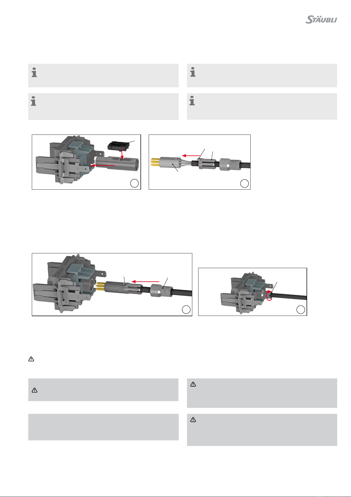
将 CTD-NET 从支撑块中拔出
(图16)
前,请检查插头是否损坏(弯曲、断裂…)
• 轻拉电缆以检查触子是否被牢固地插入支撑块。
决于电缆外径。
注意
完成压接并且组装到触子支撑块中之后,以及在首次连接之
• 将整个装置插入触子支撑块中。
触子支撑块C的平面须与主体内平面贴合,确保位置正确。
• 握住电缆的同时拧紧螺母 M,以避免电缆旋转。
注意
只能用手拧紧螺母(不使用工具)。拧紧螺母后可见的螺纹量取
将螺母 M 推到锁紧圈 B 上。
(图15)
将锁紧圈 B 连接触子支撑块 C。
将引导部分 D 置于触子支撑块 C 的平面上区域上。
(图14)
(图12)
将固定夹A安装在插针主体的凹槽内,然后整体推入模块支撑块。
听到“咔哒”声,即表示已完全插入。
(图13)
注意事项:
关于如何在框架内插入及拆卸模块支撑块,请参阅第22 – 23
页。
触子支撑块安装
注意事项:
如果通用支撑块采用侧面出线的4号外壳,例如CT-CH4-S
(Order No 332404),请联系我们确认。
Assembly in contact carrier
Note:
Please refer to pages 22 – 23 for correct insertion and
removing of carrier in frame�
(ill. 12)
Mount retaining clip Ain the groove of the pin body and push
everything into contact carrier�
A “click” sound is heard once fully inserted�
(ill. 13)
Connect the clamp ring Bto the contact carrier C�
Place the leading part Dover the flat area of the contact
carrier C�
(ill. 14)
•Push nut Mover the clamp ring B�
(ill. 15)
•Insert the whole unit in the contact carrier�
Ensure that the position of the flat part is correct�
•Tighten nut Mwhile holding the cable to avoid any cable rota-
tion�
Attention
Tighten the nut only by hand (without tool)� The amount of
thread that is visible after tightening the nut depends on the
outside diameter of the cable�
Attention
After crimping and assembly into the contact carriers, and
before first connection, check that the plugs are not dam-
aged (bent, broken…)
•Check that contacts are securely inserted in the carrier by gen-
tly pulling the cable�
Clic
Note:
If the universal carrier is used in combination with the size4
housing with side cable entry, for example CT-CH4-S (Order
No� 33�2404), please contact us for clarification�

10 / 24
17
CT-NET-AWZ D
16
1
2
3
4
• 然后推动同芯棒 D ,将触子从背面推
出。
同轴 RG58 1.5 GHz
插座侧
触子孔位,直到听到咔哒声。
3. 再用螺丝刀按下固定夹另一侧。
4. 拔出触子主体
拔出触子
(图17)
• 将退针工具 CT-NET-AWZ 从正面插入
1. 对 CT-Net 主体持续轻微用力。
2. 用螺丝刀按下固定夹一侧。
Extraction of CTD-NET from
carrier
(ill. 16)
1. Apply a slight continuous force on
the CT-Net tube�
2. Use the screwdriver to press the first
clip�
3. Press the second clip with the
screwdriver�
4. Pull out the contact insert
Extraction of contacts
(ill. 17)
•Insert the extraction tool CT-NET-AWZ
from the front side into the contact
insert until you hear a click�
•Then with the drift Dpush out the
contact�

11 / 24
2
1
2133
1
2
3
按指定尺寸调整剥线器 CT-AIWZ/COAX,然后剥去电缆绝缘层。
电缆组装
(图3)
压接钳 CT-CZ/COAX
订货号 333010
电缆准备
剥线器 CT-AIWZ/COAX
订货号 333011
(图2)
(图1)
1模块支撑块/Module carrier
2固定夹/Retaining clip
3插针主体/Socket body
工具准备
2固定夹/Retaining clip
3插座主体/Socket body
序号/Pos. 描述/Description
1模块支撑块/Module carrier
序号/Pos. 描述/Description
插针侧
Coaxial RG58 1.5 GHz
Pin sideSocket side
(ill. 1)
Insulation stripper CT-AIWZ/COAX
Order No� 33�3011
(ill. 2)
Crimping pliers CT-CZ/COAX
Order No� 33�3010
Cable preparation
(ill. 3)
Adjust the insulation stripper CT-AIWZ/COAX according to the
indicated dimensions and strip the cable�
Tools required

12 / 24
5
6
7
8
9
4
A
C
注意事项:
关于如何在框架内插入及拆卸模块支撑块,请参阅第 22 - 23
页。
(图9)
• 将压接套筒压接在指定位置 RG58 =
541 mm 或 RG59 = 648 mm。
(图8)
• 将压接套筒套在屏蔽层上。
(图7)
• 将屏蔽线推到压接外壳上。
(图6)
• 将带线端子插入压接外壳中,直到触
子插入内部绝缘体中。
(图5)
• 将电缆穿过压接套筒C。
注意事项:
压接前后,必须能在观察孔中看
到导线。
(图4)
• 将电缆芯体沿轴向插入触子的压接套
筒直到底部止位。
• 放置压接钳。
• 进行压接。
注意事项:
插座和插头的电缆压接步骤相同。
Cable assembly
Note:
The assembly procedures for
sockets and plugs are identical�
(ill. 4)
•Insert single conductor in axial direc-
tion into crimping sleeve of contact as
far as it will go�
•Place in crimping pliers�
•Perform crimping process�
Note:
Wire must be visible in the sight
hole before and after crimping�
(ill. 5)
•Slip crimp sleeve C onto the cable�
(ill. 6)
•Insert the cable into the crimp hous-
ing until the contact engages in the
inner insulator�
(ill. 7)
•Push the shield wires over the crimp
housing�
(ill. 8)
•Slip the crimp sleeve over the shield�
(ill. 9)
•Crimp the crimp sleeve in the re-
quired position RG58 = 5�41 mm
or RG59 = 6�48 mm�
Note:
Please refer to pages 22 – 23 for correct insertion and
removing of carrier in frame�

13 / 24
A
1
2
3
4
10
11
(图11)
1. 对同轴同轴持续轻微用力。
2. 用螺丝刀按下固定夹一侧。
3. 再用螺丝刀按下固定夹另一侧。
4. 拔出触子主体
拔出触子
(图10)
将固定夹A安装在插针主体上,然后整体
推入模块支撑块。
听到“咔哒”声,即表示已完全插入。
(ill. 10)
Mount retaining clip Aon pin body and
push everything into contact carrier�
A “click” sound is heard once fully
inserted�
Extraction of contacts
(ill. 11)
1. Apply a slight continuous force on
the CT-Net tube�
2. Use the screwdriver to press the first
clip�
3. Press the second clip with the
screwdriver�
4. Pull out the contact insert
Clic

14 / 24
1
3456789 2
13456789 2
序号/
Pos. 描述/Description
1插座/Socket
2固定夹/Retaining clip
3绝缘套/Insulator
4插座/Socket
5垫片/Spacer
6套筒/Sleeve
7橡胶/Rubber
8锁紧圈/Ring
9螺母/Nut
订货号
Order No.
型号
Type
33.0230 CT-B-COAX-RG316/U
33.0231 CT-B-COAX-RG58
插座侧
序号/
Pos. 描述/Description
1插针/Pin
2固定夹/Retaining clip
3绝缘套/Insulator
4插针/Pin
5垫片/Spacer
6套筒/Sleeve
7橡胶/Rubber
8锁紧圈/Ring
9螺母/Nut
订货号
Order No.
型号
Type
33.0630 CT-S-COAX-RG316/U
33.0631 CT-S-COAX-RG58
插针侧
同轴 RG316/RG58 2.4 GHz
Coaxial RG316/RG58 2.4 GHz
Pin side
Socket side

15 / 24
3
4
5
2
1
6
(7)
(6)
(8)
螺母
锁紧圈
橡胶
电缆
(图6)
首先将单个零件(螺母 8、锁紧圈 7 和橡胶 6)按如下方式套在电缆
上。橡胶要靠近电缆一侧的尾端。
注意事项:
插针和插座侧的安装步骤相同!
电缆准备
(图5)
剪线钳
(图4)
螺丝刀尺寸 0
开口扳手压接:9 mm, 10 mm
开口扳手 SMA:8 mm, 11 mm
(图3)
剥线器。
使用适合 RG58、RG316/U、RG174、
RG188 的剥线器。
(图2)
定位块 MES-CZ-CTD0,6-COAX-RG,
订货号 333914
注意事项:
操作说明 MA419
wwwstaublicom/electrical
(图1)
压接钳 CTD-M-CZ,
订货号 333900
工作准备 Tools required
(ill. 1)
Crimping pliers CTD-M-CZ,
Order No� 33�3900
Note:
Operating instructions MA419
www�staubli�com/electrical
(ill. 2)
Locator MES-CZ-CTD0,6-COAX-RG,
Order no� 33�3914
(ill. 3)
Insulation stripper�
Use a suitable insulation stripper for
RG58, RG316/U, RG174, RG188�
(ill. 4)
Screwdriver size 0
Open-end wrench crimp: 9 mm, 10 mm
Open-end wrench SMA: 8 mm, 11 mm
(ill. 5)
Side cutting pliers
Cable preparation
Note:
Pin and socket side assembly procedure is identical!
(ill. 6)
First place single parts (nut 8, ring 7and rubber 6) on the cable as
shown� The rubber is on the side closest to the cable end�
Cable
Rubber
Ring
Nut

16 / 24
7
10 0/-0.2 (mm)
8
(6)
7 0/-0.2 (mm)
9
介电绝缘层
(图9)
将介电绝缘层剥去 7 0/-02 mm。
内层导体准备
橡胶
屏蔽编织层
(图8)
使屏蔽编织层成扇形散开。将橡胶 6 向前移动,直至与护套齐平。
屏蔽编织层均匀贴合在橡胶端面。
屏蔽编织层准备
注意
请勿损坏屏蔽编织层。
外部护套屏蔽编织层
(图7)
将绝缘层(外部护套)剥掉 10 0/-02 mm。这适用于所有类型电缆。
(ill. 7)
Strip the insulator (outer sheath) to 10 0/-0�2 mm� This applies to
all cable types�
Shielding braid Outer sheath
Attention
Do not damage the shielding braid�
Shielding braid preparation
(ill. 8)
Fan out shielding braid� Move rubber 6forward until it is flush with
the sheath� Place shielding braid around the rubber�
Shielding braid
Rubber
Inner conductor preparation
(ill. 9)
Strip the dielectric insulator to 7 0/-0�2 mm�
Dielectric insulator

17 / 24
10
(5)
11
(3)
(4)
12
压接区域
观察孔
介电绝缘层
屏蔽编织层
套筒
注意事项(图12):
压接前后,必须能在观察孔中看到导线。
(图11)
首先,将垫片 4 推到内层导线上,直至接触到介质绝缘层。然后,将
插针或插座 3 置于内层导线上,并将其推至垫片处。
最后,使用压接钳 CT-MC-Z(333380) 按照 MA079 操作说明进行
压接。
使用定位块 MES-CZ-CT0,6-COAX-RG(183808) 进行正确的压接
定位。
对于 RG58 电缆,将压接钳位置调整为“SEL No 4”,对于 RG174
、RG188、RG316/U 电缆,将压接钳位置调整为“SEL No2”。
垫片
内层导线
触子
介电绝缘层
内层导线端口
(图10)
将套筒 5 推到介电绝缘层上,直至接触到屏蔽编织层。
屏蔽套筒安装 Shielding sleeve assembly
(ill. 10)
Push the sleeve 5over the dielectric insulator until it touches the
shielding braid�
Inner conductor termination
Dielectric insulator
Pin or socket
Inner conductor
Spacer
(ill. 11)
First push the spacer 4over the inner conductor until the dielec-
tricum insulator� Then place the pin or socket 3over the inner
conductor and push back until it reaches the ring�
Finally, use the crimping pliers CT-MC-Z (33�3380) to crimp ac-
cording to MA079 operating instructions�
Use locator MES-CZ-CT0,6-COAX-RG (18�3808) for correct
crimp positioning�
For RG58 cables adjust crimping pliers position to “SEL No� 4”,
and “SEL No�2” for RG174, RG188, RG316/U cables�
Note (ill. 12):
The conductor must be visible in the sight hole, before and
after the crimping process�
Sleeve
Shielding braid Dielectric insulator
Sight hole
Crimp area

18 / 24
13
14
(2)
(3) (4)
15
(2)
(1)
(8) SW, A/F 10 mm
SW, A/F 9 mm
max. 1 mm
螺母
绝缘体
触子
(图15)
将触子 1 放在绝缘套 2 上,拧紧螺母 8。拧紧时,触子和螺母之间
最多只允许有 1mm 的间隙。
(图14)
将绝缘座 2 推到触子 3 上,然后放在垫片 4 上。
垫片触子
绝缘套
(图13)
使用剪线钳剪断伸出套筒的编织层。为防止编织层与内层导体接
触,编织层不能伸出套筒外。
编织电线不能伸出套筒。
编织电线
触子绝缘套及触子组装 Assembly of insulator and pin/socket
Braid wires
Braid wires should not project beyond the sleeve.
(ill. 13)
Use the side cutting pliers to cut o any braid wires that project
beyond the sleeve� To prevent contact between braid wires and
inner conductor, braid wires must not project beyond the sleeve�
Insulator
Pin or socket Spacer
(ill. 14)
Push the insulator 2over the pin or socket 3and onto the spacer
4�
(ill. 15)
Place the pin/socket 1over the insulator 2, and screw it onto
the nut 8� When screwed, a maximum 1 mm gap is permitted
between the pin/socket and nut�
Pin/socket
Insulator
Nut

19 / 24
16
(图16)
插入触子并用固定夹锁定。
支撑块内安装已压接触子
注意事项:
关于如何在框架内插入及拆卸模块支撑块,请参阅第 22 - 23
页。
Note:
Please refer to pages 22 – 23 for correct insertion and
removing of carrier in frame�
Assembly of crimped pin and socket contacts in
carrier
(ill. 16)
Insert contacts and lock with the retaining clip�

20 / 24
17 18
SW, A/F 8 mm
SW, A/F 11 mm
19
(图19)
插入触子并用固定夹锁定。
使用开口扳手防止 SMA 触子旋转。
注意事项:
关于如何在框架内插入及拆卸模块支撑块,请参阅第 22 - 23
页。
在支撑块中安装SMA触子
(图17 - 18)
将 SMA 连接器拧到 CombiTac SMA 触子上。最大拧紧扭矩为 1 N
m。
与 SMA 端口组装
同轴 SMA 6 GHz
Coaxial SMA 6 GHz
Assembly with SMA termination
(ill. 17 - 18)
Screw your SMA connector onto the CombiTac SMA contact�
Max� tightening torque 1 N m�
Assembly of SMA pin and socket contacts in
carrier
Note:
Please refer to pages 22 – 23 for correct insertion and
removing of carrier in frame�
(ill. 19)
Insert contacts and lock with the retaining clip�
The hexagon prevents the SMA contacts from rotating�
Other manuals for MA417-1
2
Table of contents
Other Staubli Industrial Equipment manuals


