Staubli EvoTrak lite User manual

1 / 28
EvoTrak lite EvoTrak lite
Model overview of two-pole solutions
EvoTrak lite EvoTrak liteEvoTrak lite EvoTrak lite
目录
安全须知2
已交付的部件4
可能的组合方式5
建议工具6
壳体结构准备
- 编码 8
将插芯装配到绝缘体中
- 电缆格兰头安装 10
电缆准备
- 非屏蔽电缆 10
- 屏蔽电缆 11
将压接的插芯插入绝缘体内14
- 电缆格兰头紧固 15
- 电缆端子或铜排安装 15
- IP2X 母端安装 16
固定部件安装17
安装固定侧直型连接器19
金属部件接地19
连接和断开 20– 22
LITE-S-M-Px; LITE-S-F-Px
LITE-S-M-Px; LITE-X-Px
取出插芯24
注意25
Content
Safety Instructions �����������������������������������������������������������������������2
Delivery state of components�������������������������������������������������������4
Possible combinations�����������������������������������������������������������������5
Suggested tools ��������������������������������������������������������������������������6
Preparing the configuration body
- Coding ��������������������������������������������������������������������������������������8
Assembling the contacts into the insulators
- Positioning of cable gland��������������������������������������������������������10
Cables preparation
- Unshielded cables�������������������������������������������������������������������10
- Shielded cables�����������������������������������������������������������������������11
Inserting the crimped contact into the insulator��������������������������14
- Cable gland tightening�������������������������������������������������������������15
- Cable lug or busbar mounting �������������������������������������������������15
- Assembling the female IP2X protection������������������������������������16
Mounting the fixed connector part ���������������������������������������������17
Mounting the straight fixed connector����������������������������������������19
Grounding the metal parts of straight connectors ����������������������19
Connecting and disconnecting ������������������������������������������20 – 22
LITE-S-M-Px; LITE-S-F-Px
LITE-S-M-Px; LITE-X-Px
Extracting contacts��������������������������������������������������������������������24
Notes ����������������������������������������������������������������������������������������25
两极连接器模型概览
MA425 (中_英)
安装说明
MA425 (cn_en)
Assembly instructions

2 / 28
安全指令 Safety instructions
仅可使用 Stäubli 指定的组件和工具。自行装配时,切勿背离本手
册所述的制备及装配说明,否则 Stäubli 无法保证产品安全性或
性能达到官方技术参数。请勿以任何方式修改产品。
Use only the components and tools specified by Stäubli� In case of
self-assembly, do not deviate from the preparation and assembly
instructions as stated herein, otherwise Stäubli cannot give any
guarantee as to safety or conformity with the technical data� Do not
modify the product in any way�
可与 Stäubli 元件插合的非 Stäubli 原厂制造的连接器,在某些情
况下,某些制造商甚至将其描述为“与 Stäubli 兼容”,但该连接器
并不符合长期稳定安全的电连接要求,而且出于安全考虑,不得
与 Stäubli 元件插合在一起。因此,Stäubli 对因此类连接器(即未
经 Stäubli 批准)与 Stäubli 元件插合而造成的任何损失不承担任
何责任。
Connectors not originally manufactured by Stäubli which can be
mated with Stäubli elements and in some cases are even described
as ”Stäubli-compatible” by certain manufacturers do not conform
to the requirements for safe electrical connection with long-term
stability, and for safety reasons must not be plugged together with
Stäubli elements� Stäubli therefore does not accept any liability for
any damages resulting from mating such connectors (i�e� lacking
Stäubli approval) with Stäubli elements�
如您未遵守上述警告,则 Stäubli Electrical Connectors (Stäubli)
不承担任何责任。
Stäubli Electrical Connectors (Stäubli) does not accept any
liability in the event of failure to observe these warnings�
IEC 60417-6182
安装需电气专业知识 Installation, electrotechnical expertise
产品可由具备电气技能或受过此方面指导的人员依照适用的
安全法规进行装配或安装。
The products may be assembled and installed by electrically skilled
or instructed persons duly observing all applicable safety regula-
tions�
IEC 60417-6042
注意电击风险 Caution, risk of electric shock
请在断电状态下工作
操作电气装置时,请遵守五项安全规定。
各电气装置确定后,应按照规定顺序执行以下五项基本要求(除
非另有必要理由):
• 完全分离;
• 确保不会重新连接;
• 确认无工作电压;
• 进行接地和短路;
• 针对临近带电部件提供防护。
任何从事此工作活动的人员均应具备电气技能或受过此方面指
导,或者由同等能力的人员监督。
来源:EN 50110-1:2013
Work in a de-energized state
Follow the five safety rules, when working on electrical installations�
After the respective electrical installations have been identified,
the following five essential requirements shall be undertaken in the
specified order unless there are essential reasons for doing other-
wise:
•disconnect completely;
•secure against re-connection;
•verify absence of operating voltage;
•carry out grounding and short-circuiting;
•provide protection against adjacent live parts�
Any person engaged in this work activity shall be electrically skilled
or instructed, or shall be supervised by such a person�
Source: EN 50110-1:2013
最终应用时,还应检查电击防护。 Protection against electric shock shall be checked in the end-use
applications too�
IEC 60417-6070
在负载下请勿断开连接 Do not disconnect under load
允许带电插拔。 Plugging and unplugging when live is permitted�
3 / 28
安全指令 Safety instructions
ISO 7000-0434B
注意 Caution
每次使用连接器前,需提前检查外部是否有缺陷(尤其是绝缘层)
如有安全疑虑,必须咨询专业人员或更换连接器。
Each time the connector is used, it should previously be inspected
for external defects (particularly the insulation)� If there are any
safety concerns, an electrically skilled person must be consulted
or the connector must be replaced�
带外壳应用的连接器的防水功能可参考相关产品的IP保护等级。 The plug connectors are watertight in accordance with the
product specific IP protection class�
未插合的连接器必须防潮防尘。被污染的公母连接器不应插合使
用。
Unmated plug connectors must be protected from moisture and
dirt� The male and female parts must not be plugged together
when soiled�
产品使用说明或技巧 Useful hint or tip
更多技术参数请见产品目录。 For further technical data please see the product catalog�

4 / 28
A
A
A
B
B
B
C
C
C
D
D
E
E F
F
已交付的部件 Delivery state of components
壳体结构公头 Male configuration body
壳体结构面板插座 Receptacle configuration body
壳体结构母头 Female configuration body
A壳体结构 AConfiguration body
B 编码针 BCoding pin (optional)
C 插芯 CContact
D电缆格兰头 DCable gland
E 屏蔽法兰(触头+卡箍) EShield clamp (contact + retaining ring)
F IP2X 触摸保护,可选 FIP2X protection (optional)

5 / 28
可能的组合方式 Possible combinations
母头面板插座
Panel receptacle female
直型插拔侧公头
Straight mobile part male
直型母头
Straight part female

6 / 28
1
2
推荐工具 Suggested tools
(图 1)
压接钳,见表1
(ill. 1)
Crimping pliers, see Tab� 1
表 1/Tab. 1
MECATRACTION SU 210 K
+ 压接钳夹头/die holder S21
MECATRACTION ESU 137
+ 压接钳夹头/die holder U137C12
压模
Crimping die
压模
Crimping die
压接插芯
Crimp contact 插芯截面积
Cable cross-section
mm2
液压压接工具和压接钳夹头
Hydraulic crimping tool and die holder
压模
Crimping die
直边长度
Flat side
mm
宽度
Width
mm
插针
Pin
插座
Socket 六角压接
Hex. crimp
19.3506 19.3520 10
MECATRACTION SU 210 K + S21
或/or
MECATRACTION ESU 137 + U137C12
ELSV20
C12 ELS
5.8 ± 0.15 7
19.3507 19.3521 16
MECATRACTION SU 210 K + S21
或/or
MECATRACTION ESU 137 + U137C12
FLSV20
C12FLS
6.8 ± 0.15 7
19.3508 19.3522 25
MECATRACTION SU 210 K + S21
或/or
MECATRACTION ESU 137 + U137C12
TN25V20
C12TN25
8.1 ± 0.15 8
19.3509 19.3523 35
MECATRACTION SU 210 K + S21
或/or
MECATRACTION ESU 137 + U137C12
TN35V20
C12TN35
9.3 ± 0.15 8
19.3510 19.3524 50
MECATRACTION SU 210 K + S21
或/or
MECATRACTION ESU 137 + U137C12
TN50V20
C12TN50
11± 0.15 12
19.3511 19.3525 70
MECATRACTION SU 210 K + S21
或/or
MECATRACTION ESU 137 + U137C12
TN70V20
C12TN70
12.6 ± 0.15 12
(图2)
扭矩扳手(史陶比尔不提供)和嵌件。
LITE-TO/CGM25,
订货号 19�2929
(ill. 2)
Torque wrench (not provided by Stäubli)
and insert�
LITE-TO/CGM25,
Order No� 19�2929

7 / 28
3
4
5
6
7
8
(图3)
电工刀,用于剥开电缆。
(ill. 3)
Electrician knife to strip the cable�
(图4)
可调节螺丝刀
2 - 10 N m (示例:FACOM 404)。
M6螺栓内六角套筒, 长度大约 100 mm。
史陶比尔不提供。
(ill. 4)
Screwdriver with Vernier Adjustment
2 - 10 N m (example: FACOM A 404)�
Hexagon socket for M6 screws, length
approx� 100 mm�
Not supplied by Stäubli�
(图5)
内六角扳手 4 mm。
(ill. 5)
Allen key 4 mm�
(图6)
用于剥屏蔽电缆金属编织层的剪线钳。
(ill. 6)
Wire cutter to strip the metallic braid of
the shielded cable�
Not supplied by Stäubli�
(图7)
安装屏蔽法兰卡箍的专用钳
(Facom,411A17)。
(ill. 7)
Special pliers to install the retaining ring
on the shield clamp (Facom, 411A�17)�
Not supplied by Stäubli�
(图8)
用于拆卸插芯的工具和推片。
LITE-TO/CT,
订货号 192916
LITE-TO/CT-PSH,
订货号 192917
(ill. 8)
Removal tool and pusher for disassem-
bling contacts�
LITE-TO/CT,
Order No� 19�2916
LITE-TO/CT-PSH,
Order No� 19�2917
8 / 28
9
壳体结构准备 Preparing the configuration body
编码 Coding
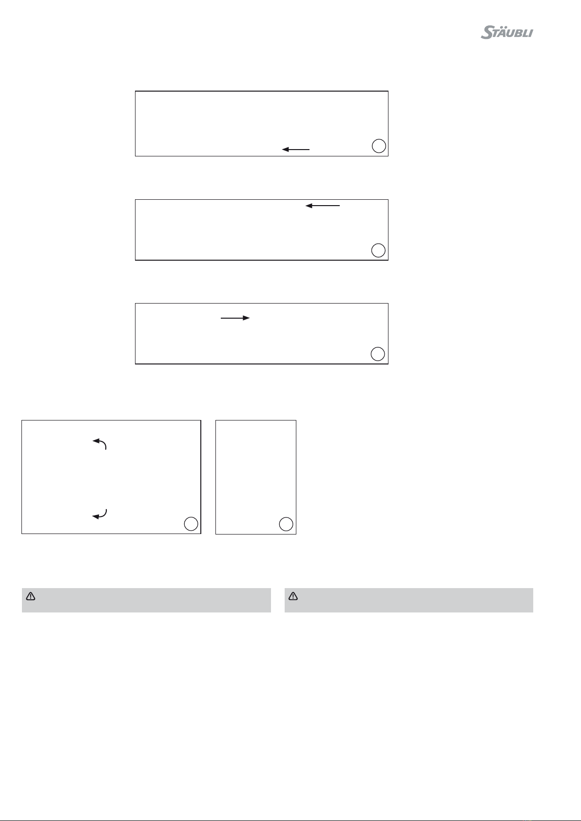
(图9)
多极连接器应避免误插,以防止不当连接。
(ill. 9)
Multipole connectors must be polarized to prevent improper
mating�
为了对连接器进行编码,需要在壳体中使用编码针。每个单极有2个
编码孔。
为固定和插拔端选择壳体结构,然后根据以下编码表插入编码针。
听到“咔哒”声时,即表明编码针到了壳体的最终位置。
Coding consists of using coding pins that will be inserted into the
configuration bodies of both fixed and mobile parts� Each single
pole has 2 holes to clip in a coding pin�
Select the configuration body for the fixed and mobile part, then
insert a coding pin according to the desired combination (see
below for coding sequence options)�
The final position of the coding pins in the insulator is obtained
when a “click” sound is heared� The correct fit is additionally
checked by pulling the coding pin�
遵守插拔端和固定端之间的编码顺序很重要。 It is necessary to respect the coding sequence between the fixed
and mobile part�
插拔端壳体结构
Mobile conguration body
固定端壳体结构或面板安装插座
Fixed conguration body or panel mount
编码 1/Code 1
编码 2/Code 2

9 / 28
插拔端壳体结构
Mobile conguration body
固定端壳体结构或面板安装插座
Fixed conguration body or panel mount
编码 3/Code 3
编码 4/Code 4
编码 5/Code 5
编码 6/Code 6
10 / 28
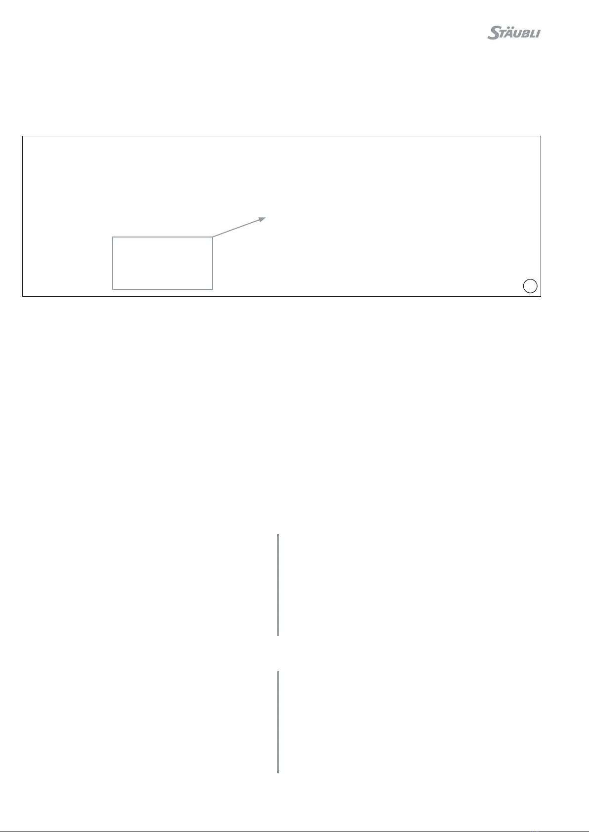
11
10
Ø max. 17.5 mm
将插芯装配到绝缘体中 Assembling the contacts into the insulators
电缆格兰头紧固 Positioning of cable gland
注意:
电缆格兰头不适用于动态应用场景(侧向活动)。电缆夹紧法
兰系统须由客户或集成商提供。
Note :
The cable glands are not suitable for dynamic application
(lateral movements)� A cable flanging system must be provided
by the customer or the integrator�
表 2/Tab. 2
电缆准备 Cables preparation
非屏蔽电缆 Unshielded cables
(图10)
将电缆格兰头套到电缆上。
(ill. 10)
Place the cable gland on the cable�
注 意( 表 2 ):
电缆格兰头的选择取决于电缆外
径,且必须符合铁路电缆规范。用户应
对其选择负责。
Note (Tab. 2):
The cable gland depends on the
cable’s outer diameter and must
be compliant to railway standards�
The user is responsible for choosing
accordingly�
(图11)
使用电工刀剥去相应长度的电缆绝缘
层,参见表3
(ill. 11)
Strip the cable with the electrician knife,
according to the lengths in Tab� 3�
表 3/Tab. 3
电缆截面积
Cable cross section
mm²
长度 L
Length L
mm
10 15 +3/-1
16 18 +3/-1
25 20 +3/-1
35 20 +3/-1
50 20 +3/-1
70 20 +3/-1
L
电缆格兰头
Cable gland
电缆格兰头类型
Type of cable gland insert 订货号
Order No.
紧固范围 (mm)
Tigthening range (mm)
M25
LITE/CG-N5HT 19.2746 6 – 9
LITE/CG-N4HT 19.2747 8 – 13.5
LITE/CG-N2HT 19.2749 12 – 16
LITE/CG-N3HT 19.2748 14 – 18
LITE/CG-N1HT 19.2745 16 – 20
LITE/CG-N9HT 19.2753 Blindstopfen/Stopper
11 / 28
12
14
X
Y
Z
13
(图12–13)
• 将电缆插入压接套,用力推到底。
• 使用相应的压模进行压接,参见表1将
导线固定在套管中的适当位置(轴向用
力 推 )。
• 在压接前,务必注意将两个压模对齐。
(ill. 12 – 13)
•Insert the stripped cable in the crimp-
ing sleeve until the end�
•Crimp the sleeve with the hexagonal
dies, Tab� 1� Hold the conductor in
position of the sleeve (push axially)�
•Carefully align the dies while crimping�
注意
压接前后,必须确保能在窥视孔中
看到导线
Attention
Conductor wires must be visible
in the sight hole before and after
crimping�
屏蔽电缆 Shielded cables
剥开电缆 Cable stripping
电缆截面积
Cable cross section
长度X
Length X
长度Y
Length Y
长度Z
Length Z
mm² mm mm mm
10 15 +3/-1 60 +5/-5 75 +5/-5
16 18 +3/-1 60 +5/-5 75 +5/-5
25 20 +3/-1 60 +5/-5 75 +5/-5
35 20 +3/-1 60 +5/-5 75 +5/-5
50 20 +3/-1 60 +5/-5 75 +5/-5
70 20 +3/-1 60 +5/-5 75 +5/-5
电流内芯绝缘层直径最大 Ø 16.5mm
max. Ø 16.5 mm on core insulation of cable
12 / 28
15
16
17
18 19
(图15)
• 使用专用钳,将固定环滑到电缆的外层绝缘体上。
(ill. 15)
•By using the special pliers, slide the retaining ring over the
upper insulator on the cable�
(图16)
• 将屏蔽法兰插入金属编织层和内层绝缘体之间。确保长度达到 z (
见表4,第 11页)。
(ill. 16)
•Insert the shield clamp between the metallic braid and the inner
insulator� Be sure to respect length Z (see Tab� 4, p� 11)�
(图17)
• 使用固定环和专用钳子将金属编织物固定在屏蔽法兰上。
(ill. 17)
•Block the metallic braid onto the shield clamp by using the
retaining ring and the special pliers�
(图18 – 19)
• 将金属编织物折叠在固定环上,并剪掉超出的编织物。
(ill. 18 – 19)
•Fold the metallic braid over the retaining ring and cut o the
excess braid�
注意
请勿损坏 MULTILAM!
Attention
Do not damage the MULTILAM!

13 / 28
Y22
21
20
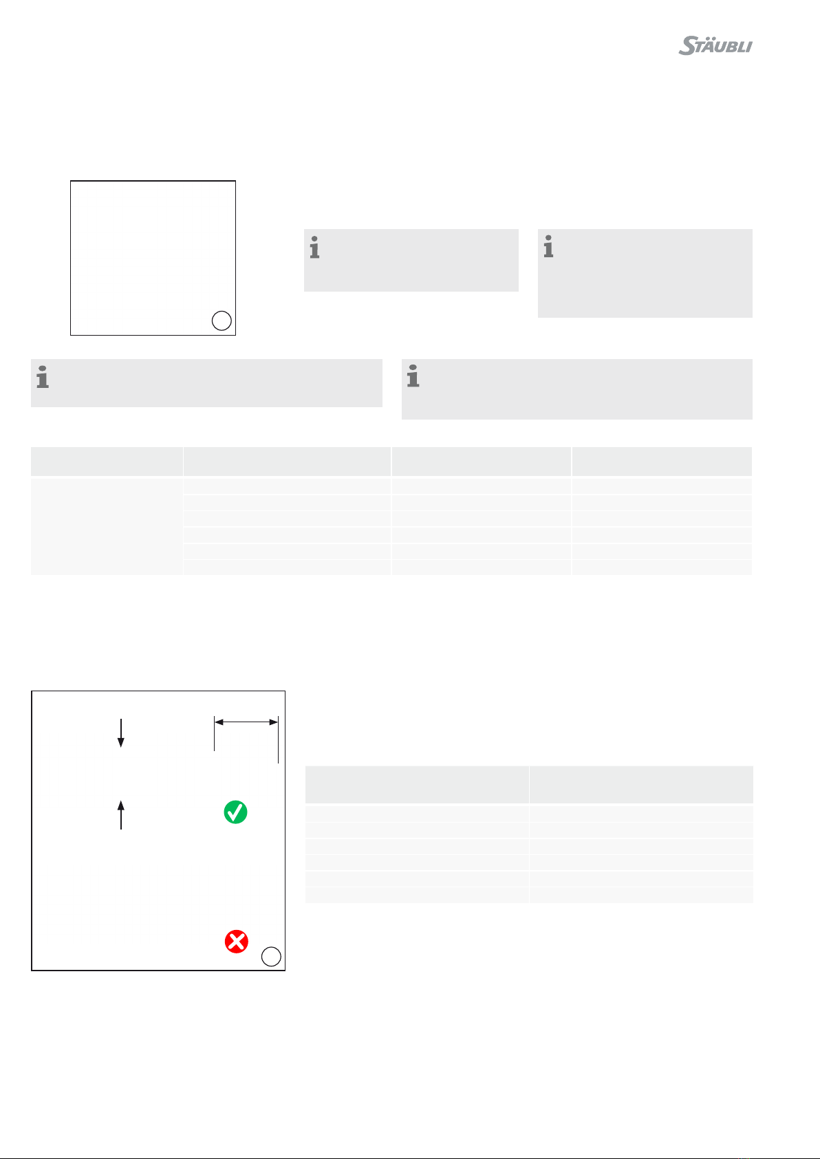
(图20–21)
• 将电缆插入压接套,用力推到底。
• 使用相应的压模压接,参见表 1。将导线固定在套管中的适当位置
(轴向用力推)。
• 在压接前,务必注意将两个压模对齐。
(ill. 20 – 21)
•Insert the cable in the crimping sleeve until the end�
•Crimp the sleeve with the hexagonal dies, Tab� 1� Hold the
conductor in position of the sleeve (push axially)�
•Carefully align the dies while crimping�
注意
压接前后,必须确保能在窥视孔中看到导线
Attention
Conductor wires must be visible in the sight hole before and
after crimping�
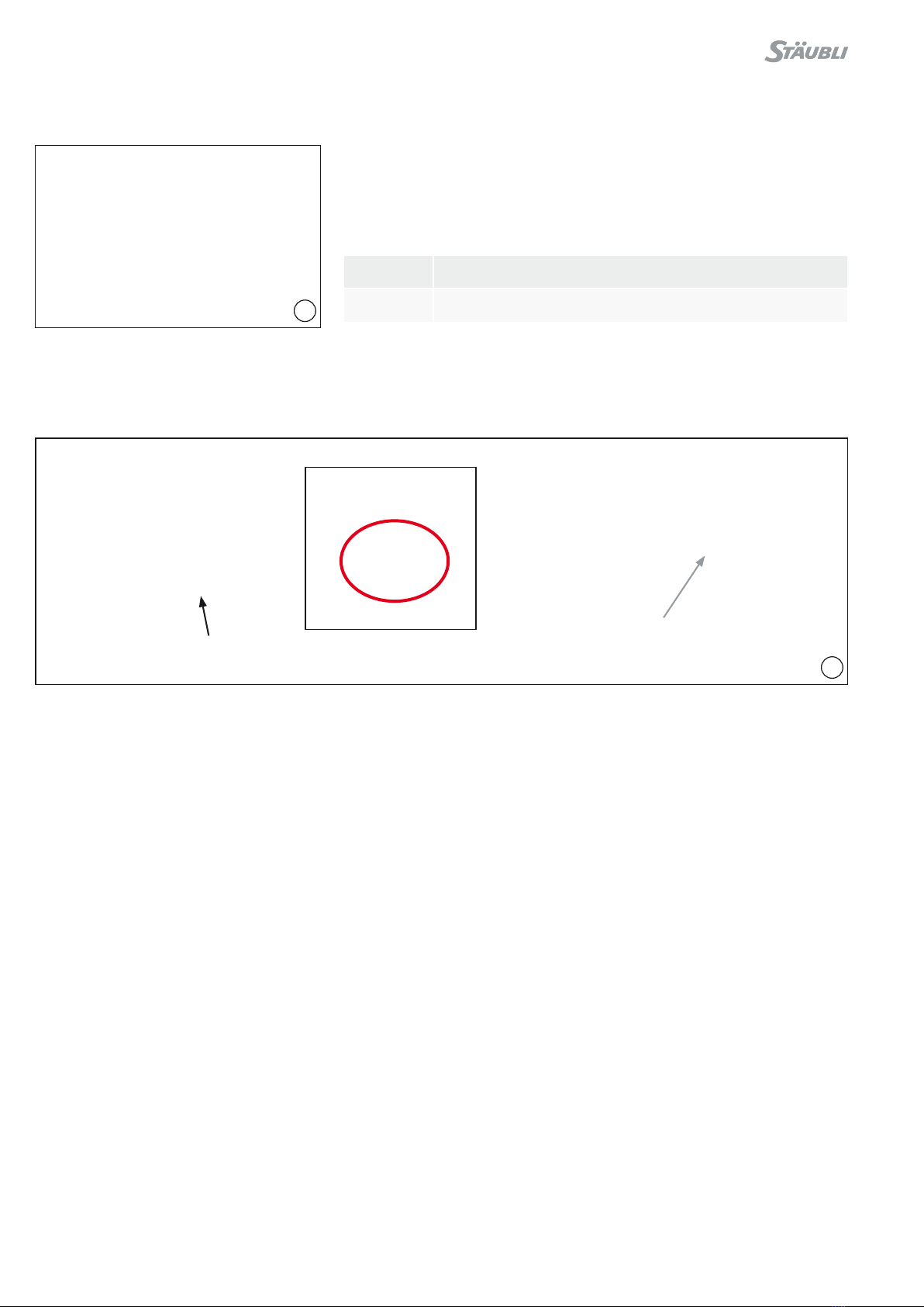
(图22)
确认屏蔽法兰与插芯(公头或母头)肩部的距离为535 +1/-3 mm
(ill. 22)
Verify the distance Ybetween the shield clamp and the shoulder
of the contact (male or female) is 53�5 +1/-3 mm�

14 / 28
23
2
1
3
将压接好的插芯插入绝缘体 Inserting the crimped contacts into the insulator
(图 23)
1. 将压接好的插芯插入其中一个壳体结构绝缘体内
2. 将屏蔽触指推入壳体的金属部分(屏蔽版本)
3. 检查插芯位置是否正确。
绝缘体内的卡爪需卡住插芯。
母头插芯:略微凹陷于绝缘体边缘
公头插芯:略微凸起于绝缘体边缘
拉动电缆以检查插芯是否正确地固定。
(ill. 23)
1. Insert the crimped contact into one of the insulators in the
configuration body�
2. Push and insert the shielding contact into the metallic part of
the configuration body (shielded versions)�
3. Check for proper contact placement�
The claws must hold the contact�
Female contact: It should be slightly recessed from the edge of
the insulation�
Male contact: it should be slightly exceed from the edge of the
insulation�
Pull on the cable to check that the contact is correctly clipped in
the insert�
插头
Pin 插座
Socket

15 / 28
24
25
电缆格兰头紧固 Cable gland tightening
(图 24)
使用扭矩扳手和嵌件拧紧电缆格兰头,确
保背面密封。
(ill. 24)
Tighten the cable gland to ensure seal-
ing in the back of the cable by using the
torque wrench and insert�
建议扭矩:
电缆格兰头CG-M25:15 N m
Recommended torque:
Cable gland CG-M25: 15 N m
在每一个极上重复这一操作。 Repeat this operation for each pole�
拧紧压力螺母直至其和密封嵌件在同一
水平。
Tighten pressure screw visual until
pressure screw and sealing insert are at
the same level�
电缆端子或铜排安装 Cable lug or busbar mounting
(图 25)
将电缆端子或铜排连接到插芯上
LITE-X/CT-S10-IT-M8 包含以下步骤:
• 将电缆端子或铜排连接到插芯上
• 将平垫圈固定在电缆端子上
• 安装锁紧垫圈(如 RipLock 垫圈)
• 紧固 A2 不锈钢 M8x20 螺钉。
拧紧扭矩:12 to 13 N m
(ill. 25)
Connecting the cable lug or busbar to the contact
LITE-X/CT-S10-IT-M8 consists of the following steps:
•Place cable lug or busbar on the contact
•Place flat washer on the cable lug
•Position lock washer (e�g� RipLock washer)
•Tighten A2 stainless steel M8x20 screw�
Tightening torque: 12 to 13 N m
注意:
电缆格兰头不适用于动态应用场景(侧向活动)。集成商必须
遵守适用的电缆固定标准:
除非电缆制造商另有约定,否则电缆必须以不大于以下值的与
格兰头间隔固定到位:
- 如果电缆沿表面水平放置,则为300 mm
- 如果电缆垂直放置,则为500 mm
Note:
The cable glands are not suitable for dynamic application
(lateral movements)�The integrator must comply with the cable
retention standards of the application:
Unless stated otherwise by the cable manufacturer, cables
must be fixed in place at intervals no larger than the following
values:
- 300mm if the cables are placed horizontally along a surface
- 500mm if the cables are placed vertically
16 / 28
27
clic
26
IP2X触摸保护母端组装 Assembling the female IP2X protection
(图27)
• 将IP2X防护装置的爪具安装在绝缘体卡爪之间。
• 推入 IP2X 保护装置,直到您听到咔嗒声。
(ill. 27)
•Position the claws of the IP2X protection between the claws of
the insulator�
•Push the IP2X protection until you hear a click�
保护帽 Protection cap
(ill. 26)
在室外时,请使用保护帽(根据需求提供)
防尘,以保护未插合的连接器。
(ill. 26)
Protection cap (on request) against
dust� To protect the unmated contacts
when outside use�
订货号
Order no.
描述
Description
19.2673 保护帽
Protection cap
17 / 28
28
固定件安装 Mounting the fixed connector part
插座装配 Receptacle assembly
在面板上安装连接器 Mounting the connector on the panel
(图28)
在面板上安装连接器时,必须根据钻孔图钻孔。
(ill. 28)
To mount the connector on the panel, drill according to the drilling
plan�
1极
1 pole
2极
2 poles
3极
3 poles
4极
4 poles
18 / 28
29
1
2
3
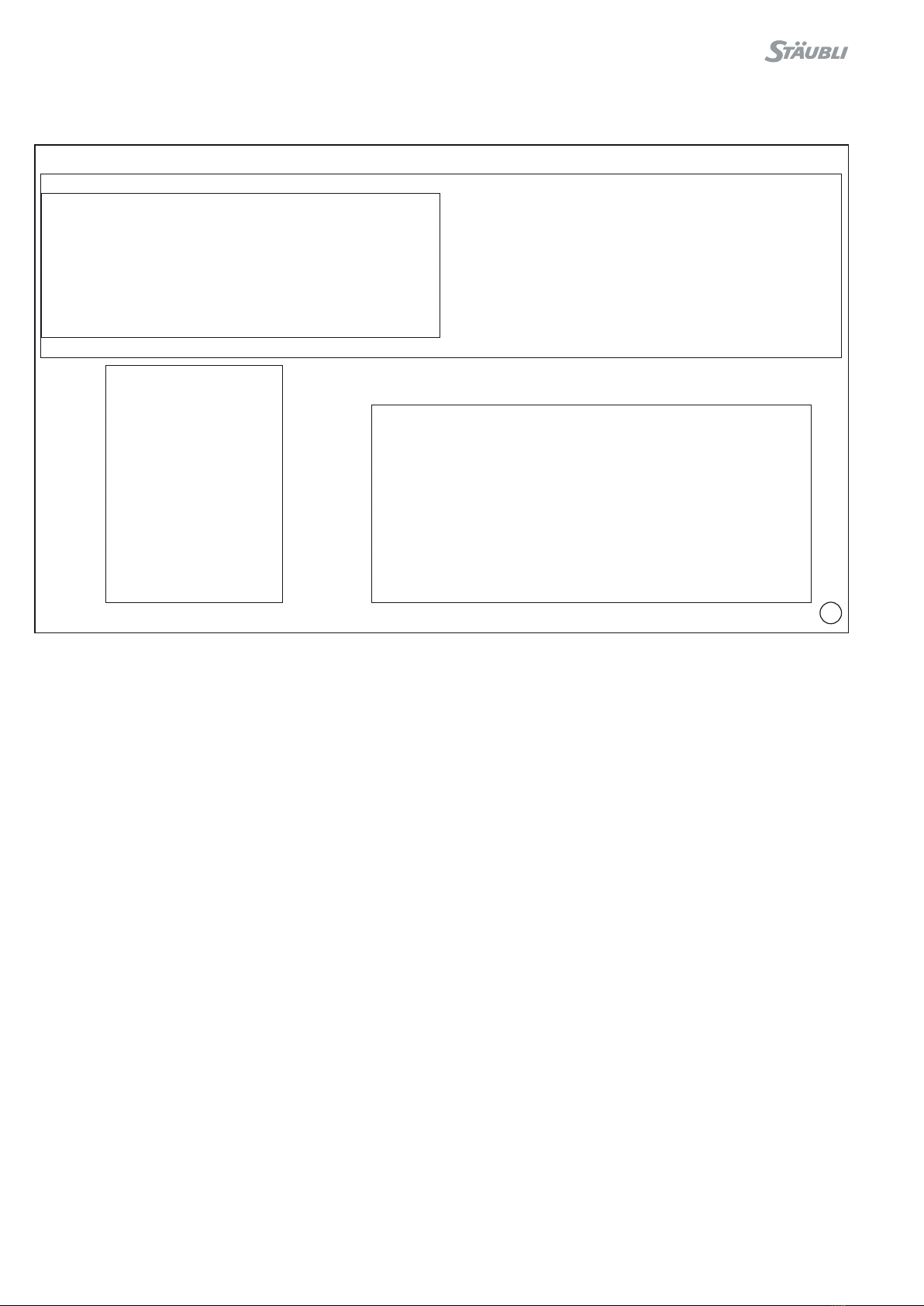
(图29)
1. 将连接器放置在面板外侧。
2. 将四个M4 螺栓穿过连接器上的4个安装孔。从柜体内侧装上螺
母。
3. 从外侧拧紧4个安装螺栓。拧紧扭矩:2-25 N m。
(ill. 29)
1. Place the connector on the outside of the panel�
2. Pass the four M4 screws through the 4 mounting holes on the
connector� Place a nut-type system on the screws on the inside
of the cabinet�
3. From the outside, tighten the 4 mounting screws� Tightening
torque: 2 to 2�5 N m�

19 / 28
31
直型连接器金属部件接地(可选) Grounding the metal parts of straight connectors
(optional)
(图31)
您可以使用连接器端板上的孔(请参见上图中的圆孔)连接接地编
织线。
孔直径:7 mm
LITE-X 面板插座具有与客户面板接触的平坦金属表面,因此无需连
接接地编织线。
(ill. 31)
To connect a ground braid, use the holes provided on the end
plates of the connectors (see the circled holes in the image
above)�
Hole diameter: 7 mm
The LITE-X panel receptacle has a flat metal surface in contact
with the customer’s panel so that a grounding braid is not neces-
sary��
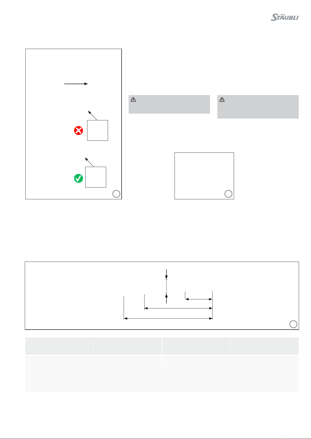
安装固定式连接器 Mounting the straight fixed connector
安装孔 Mounting holes
极数
Number of poles X (mm) Y (mm) D (mm)
1 57 ± 0.2
29 ± 0.2 33.25 +/- 0.2
2 92 ± 0.2
3 127 ± 0.2
4 162 ± 0.2
XX
YY
DD
移动和固定部件之间的连接点
Junction point between
mobile and xed part
30

20 / 28
32
连接和断开 Connecting and disconnecting
LITE-S-M-Px; LITE-S-F-Px
连接前的检查 Before connecting
检查:
• 2个锁紧螺栓。
• LITE-S-M-Px上蓝色密封件(1个密封件/极)。密封件不得有损坏。
• 插针和插座无污染。
• 黑色绝缘体部件上没有裂纹和缺角。
Check for:
•2 locking screws�
•blue seals (1 seal/pole) on the LITE-S-M-Px� They must not be
damaged�
•no pollution on pins and sockets�
•no cracks or broken corners on black insulator parts�
连接 Connection
(图32)
• 使用固定件端板上的 2 个螺纹孔连接移动连接器并将其锁定在
固定连接器中。
• 两个部件组装在一起。
• 拧紧2个锁紧螺栓。
• 使用 M6 螺钉的内六角螺丝刀拧紧固定部件的 2 颗螺栓。
• 用拧紧扭矩拧紧:8-10 N m。
(ill. 32)
•Use the 2 threaded holes in the end plates of the fixed part in
order to connect and lock the mobile connector on to the fixed
connector�
•Keep both parts together�
•Screw the 2 locking screws�
•Tighten the 2 screws of the fixed part with screwdriver Allen for
M6 screw�
•Tighten with tightening torque: 8 à 10 N m�
Table of contents
Other Staubli Industrial Equipment manuals


