STAUFF LPM-II-plus User manual

Manual
Particle Monitor
LPM-II-plus

1
As a policy of continual improvement, STAUFF reserves the right to alter the specification without prior notice.
201.031 Date of Issue: 06 November 2018
EC Declaration of Conformity
The products included in this Declaration are all variants of the following:
With or without a moisture sensor
Compatible with mineral oil/ synthetic fluids, offshore fluids, phosphate esters (inc. aerospace
versions)
With or without a keypad/ display
With or without USB download
With relay outputs
With Modbus, CAN-bus and 4-20mA outputs
These are denoted by a combination of the following codes, and the serial numbers are preceded with
16:
LPM
II
O
M
O
D
G
W
E
Product Manufacturer:
Walter Stauffenberg GmbH & Co. KG
Im Ehrenfeld 4
58791 Werdohl
Germany
The products described are in conformity with the following directives:
-2014/30/EU Electromagnetic Conformity
Certification Testing that has been carried out is in accordance with:
- DEF STAN 00-35 Part 3 issue 4 Environmental Test Methods
- BS EN 60068 range of standards covering environmental conditions
- BS EN 60529: 1992 + A2:2013 Degrees of Protection provided by enclosures (IP Code)
- BS EN 62262:2002 Degrees of Protection Provided for Electrical Equipment against External
Mechanical Impacts (IK Code)
- BS EN 60721-3-4: 1995 Part 3: Classification of Groups of Environmental Parameters and their
severities, Section 3.4

2
As a policy of continual improvement, STAUFF reserves the right to alter the specification without prior notice.
201.031 Date of Issue: 06 November 2018
Table of Contents
EC Declaration of Conformity.....................................................................................................................1
1 General Warnings and Information for the End User ..............................................................................5
1.1 General Safety Warnings..................................................................................................................5
1.3 Operator Position and Dangerous Areas..........................................................................................6
1.4 Dangers and Hazards that cannot be eliminated..............................................................................7
1.5 Personal Protective Equipment.........................................................................................................7
2 Transportation and Storage.....................................................................................................................8
2.1 Transportation and Handling Conditions...........................................................................................8
2.2 Storage .............................................................................................................................................8
3 Warranty, Limitations and Disclaimers ....................................................................................................9
4 Product Presentation.............................................................................................................................11
4.1 Benefits...........................................................................................................................................11
4.2 Product features..............................................................................................................................11
4.2.1 Moisture Sensor .......................................................................................................................11
4.2.2 Data Logger..............................................................................................................................12
5 Technical Specification..........................................................................................................................13
5.1 Performance ...................................................................................................................................13
5.2 Electrical Interface ..........................................................................................................................13
5.3 Physical Attributes ..........................................................................................................................14
5.4 Fluid Characteristics .......................................................................................................................15
5.5 Environment....................................................................................................................................15
5.6 Wetted Parts List.............................................................................................................................15
6 Product Installation and General Operation ..........................................................................................16
6.1 Installation.......................................................................................................................................16
6.1.1 Physical Procedure.............................................................................................................16
6.1.2 Electrical Interface....................................................................................................................17
6.1.3 Hydraulic Connection ...............................................................................................................23
6.2 General Operation ..........................................................................................................................26
6.2.1 Physical Checks.......................................................................................................................26
6.2.2 Front Panel Operation..............................................................................................................26

3
As a policy of continual improvement, STAUFF reserves the right to alter the specification without prior notice.
201.031 Date of Issue: 06 November 2018
6.2.3 LPM removal and Product Maintenance..................................................................................29
6.3 LPM Control....................................................................................................................................29
6.3.1 Computer Connection ..............................................................................................................30
6.3.2 PC Software Operation ............................................................................................................31
6.3.3 Settings ....................................................................................................................................32
6.4 Standard Communication Protocols ...............................................................................................40
6.4.1 Modbus.....................................................................................................................................40
6.4.2 CAN-bus...................................................................................................................................44
6.4.3 Analogue 4-20mA Modes.........................................................................................................47
6.5 Disposal..........................................................................................................................................49
7 Troubleshooting / FAQ ..........................................................................................................................50
7.1 Misuse of Product ...........................................................................................................................50
7.2 Fault Finding...................................................................................................................................50
7.2.1 LED Flashing / Fault Codes .....................................................................................................50
7.2.2 Test Status...............................................................................................................................51
7.2.3 Other Faults..............................................................................................................................51
7.3 Test Duration ..................................................................................................................................52
8 How to Order .........................................................................................................................................53
8.1 Common Features ..........................................................................................................................53
9 Related Products...................................................................................................................................54
9.1 LPM Remote Display Unit...............................................................................................................54
9.2 LPMUSBInterface ...........................................................................................................................54
9.3 LPM-DAV........................................................................................................................................55
10 Service and Recalibration....................................................................................................................56
11 Reference............................................................................................................................................57
11.1 Further Modbus Information..........................................................................................................57
11.1.1 Modbus Registers ..................................................................................................................57
11.1.2 Implementing Modbus............................................................................................................62
11.2 Further CAN-bus Information........................................................................................................64
11.2.1 Example Walk through...........................................................................................................64
11.2.2 Messages...............................................................................................................................69
11.3 Measuring Water in Hydraulic and Lubricating Fluids...................................................................72
11.4 ISO4406:1999 Cleanliness Code System.....................................................................................73
11.5 NAS1638 Cleanliness Code System (now defunct, replaced by SAE AS4059E Table 1)............74

4
As a policy of continual improvement, STAUFF reserves the right to alter the specification without prior notice.
201.031 Date of Issue: 06 November 2018
11.6 SAE AS4059 REV E Cleanliness Classification for Hydraulic fluids.............................................74
11.7 Recommendations........................................................................................................................75
11.8 Hydraulic System Target Cleanliness Levels................................................................................76
11.9 New ISO Medium Test Dust and its effect on ISO Contamination Control Standards..................77
11.10 Clean Working Practices.............................................................................................................81
5
As a policy of continual improvement, STAUFF reserves the right to alter the specification without prior notice.
201.031 Date of Issue: 06 November 2018
1 General Warnings and Information for the End User
1.1 General Safety Warnings
Do not operate, maintain or carry out any procedure before reading this manual. Any individual operating
the unit shall wear the following Personal Protective Equipment:
Protective eyewear
Safety shoes
Gloves
Overalls (or other suitable protective clothing)
Before carrying out any machine installation procedures and/or before use, one should scrupulously
follow the instructions listed in this manual. Moreover, it is necessary to comply with the current
regulations related to occupational accident prevention and safety in the workplace.
Notices aimed at the prevention of health hazards for personnel operating the machine are highlighted in
this document with signs having the following meaning:
WARNING
It relates to important information concerning the product, its use or part of this
documentation to which special attention must be paid
DANGER
It means that failure to comply with the relevant safety regulations may result in
death, serious injury or serious property damage.
In order to quickly identify the professionals concerned with reading this manual, the following definitions
were used:
OPERATOR
This is any individual whose task is to use the machine for production purposes.
The operator is aware of all the measures taken by the machine manufacturer in
order to eliminate any source of injury risk in the workplace and takes into
account the operational constraints.
PERSONNEL
INVOLVED IN
SLINGING AND
This is any individual whose task is to handle the machine or parts of it.
Personnel involved in slinging and hoisting operations are aware of the issues
regarding the safe transfer of machinery or parts of it and, therefore, uses
CAUTION
It means that failure to comply with the relevant safety regulations may result in
mild injury or property damage.

6
As a policy of continual improvement, STAUFF reserves the right to alter the specification without prior notice.
201.031 Date of Issue: 06 November 2018
HOISTING
OPERATIONS
appropriate lifting equipment, following the instructions provided by the product
manufacturer.
MACHINE
SETTER
This is any individual whose task is to set up the machine for its operation. The
machine setter is aware of the measures taken to eliminate all sources of injury
risks in the workplace and takes into account the operational constraints. The
machine setter takes all the appropriate precautions in order to operate in
utmost safety conditions.
MAINTENANCE
TECHNICIAN
This is any individual whose task is to carry out maintenance activities on the
machine. The maintenance technician is aware of the possible danger situations
that may arise and takes the appropriate precautions in order to eliminate the
risks of accidents in the workplace.
ELECTRICIAN
This is any individual whose task is to carry out maintenance activities on the
electrical wiring of the machine. The electrician is aware of the possible danger
situations that may arise and takes the appropriate precautions in order to
eliminate the risks of accidents in the workplace.
1.3 Operator Position and Dangerous Areas
No operator is required for operating the unit. However, the following areas are to be considered
dangerous: The ones close to the electric motor because of live equipment with potentially hot surfaces.
WARNING
The unit shall be taken out of service and/or dismantled in accordance with the
current regulations in force in the country where the machinery is installed
WARNING
The machinery is not suitable for outdoor use and all the electrical devices
have a protection class starting from IP 55 upwards.

7
As a policy of continual improvement, STAUFF reserves the right to alter the specification without prior notice.
201.031 Date of Issue: 06 November 2018
1.4 Dangers and Hazards that cannot be eliminated
-Electric shock risk on the electric motor; in case of motor malfunction
-Burn risk because of high temperatures
-Accidental oil leaks with consequent risk of slipping
-Hose breakage and resulting lubricant loss
With oil temperatures exceeding 40/45 °C, it is vital to be extremely careful when handling the metal
lances/the hoses and when moving the unit. Avoid direct contact with hot oil and with the filter body.
ALL EQUIPMENT SHOULD BE ALLOWED TO COOL PRIOR TO HANDLING, AFTER IT HAS
BEEN IN USE
1.5 Personal Protective Equipment
When operating the unit, personnel must be wearing safety shoes, gloves and goggles. In general, the
PPEs to be used according to the activities on the machinery are listed in the following table:
Activity
PPEs
Ordinary operation
Shoes, gloves, goggles, overall
Planned maintenance
Shoes, gloves, goggles, overall

8
As a policy of continual improvement, STAUFF reserves the right to alter the specification without prior notice.
201.031 Date of Issue: 06 November 2018
2 Transportation and Storage
2.1 Transportation and Handling Conditions
The unit is shipped in a cardboard box, encased in polyurethane foam.
The packed weight of the LPM and accessories is 2.5kg.
2.2 Storage
The unit should be stored in a suitable location away from the production area when not in use. The unit
should be stored with the caps provided on the ports. This location should not impede any other
production or personnel.

9
As a policy of continual improvement, STAUFF reserves the right to alter the specification without prior notice.
201.031 Date of Issue: 06 November 2018
3 Warranty, Limitations and Disclaimers
Stauff warrant that the products that it manufactures and sells will be free from defects in material,
workmanship & performance for a period of 12 months from the date of shipment.
Hardware/Firmware
Should the hardware prove defective during the warranty period, Stauff, at its discretion, will either repair
the defective product or replace it with an equivalent product in exchange for the defective unit without
charge for parts, labour, carriage and insurance.
Software
Stauff warrants that software will operate substantially in accordance with its functional specification for 12
months from date of shipment provided that the integrity of the operating environment has not been
compromised through misuse, inappropriate handling, abnormal operating conditions, neglect or damage
(unintentional or otherwise) or the introduction of third party product (software or hardware) that in any way
conflicts with the Stauff product.
Eligibility
This warranty extends to the original purchaser only or to the end-user client of a Stauff authorised affiliate.
How to obtain service?
To obtain service under the terms of this warranty, the customer is required to notify Stauff before the
expiration of the warranty period and to return the item in accordance with Stauff product return policy.
Any product returned for warranty repair must be accompanied by a full fault report specifying the
symptoms and the conditions under which the fault occurs. Should Stauff incur additional cost as a result
of a failure to complete the appropriate paperwork, an administrative charge may be levied.
Exclusions
This warranty shall not apply to any defect, failure or damage caused by improper use or improper or
inadequate care. Stauff shall not be obligated to provide service under this warranty if:
a) Damage has been caused by a failure to make a full and proper inspection of the product (as described
by the documentation enclosed with the product at the time of shipment) on initial receipt of the product
following shipment;
b) Damage has been caused by the attempts of individuals, other than Stauff staff to repair or service the
product;
c) Damage has been caused by the improper use or a connection with incompatible equipment or product
including software applications.

10
As a policy of continual improvement, STAUFF reserves the right to alter the specification without prior notice.
201.031 Date of Issue: 06 November 2018
Charges
Under cover of this warranty, Stauff will pay the carriage and insurance charges for the shipment of
defective product back to site of manufacture and for its return to the client’s original site of despatch
except when:
a) Stauff product return policy has not been followed.
b) Product failure is caused by any of the exclusions described above, when the customer will be liable for
the full cost of the repair (parts and labour) plus all carriage and insurance costs to and from Stauff
premises.
c) The product is damaged in transit and a contributory cause is inadequate packaging. It is the customer’s
responsibility to ensure that the packaging used to return equipment to Stauff is the same, or has
equivalent protective qualities, to that used to ship the product to the customer in the first instance. Any
damage resulting from the use of inadequate packaging will nullify Stauff obligations under this
warranty. Should the customer’s product be damaged in transit following a repair at Stauff site, a full
photographic record of the damage must be obtained (packaging and the product) to support any claim
for recompense. Failure to present this evidence may limit Stauff obligations under this warranty.
THIS WARRANTY IS GIVEN BY STAUFF IN LIEU OF ANY OTHER WARRANTIES, EXPRESS OR
IMPLIED, INCLUDING BUT NOT LIMITED TO ANY IMPLIED WARRANTY OF MERCHANTABILITY,
NON INFRINGEMENT OR FITNESS FOR A PARTICULAR PURPOSE. STAUFF LTD SHALL NOT BE
LIABLE FOR ANY SPECIAL,
INDIRECT, INCIDENTAL OR CONSEQUENTIAL DAMAGES OR LOSSES ( INCLUDING LOSS OF
DATA), WE SPECIFICALLY DISCLAIM ANY AND ALL WARRANTIES TO CUSTOMERS OF THE
CUSTOMER. THE CUSTOMER’S SOLE REMEDY FOR ANY BREACH OF WARRANTY IS THE
REPAIR OR REPLACEMENT, AT STAUFF DISCRETION, OF THE FAILED PRODUCT.
Stauff maintains a policy of product improvement and reserves the right to modify the specifications without
prior notice.

11
As a policy of continual improvement, STAUFF reserves the right to alter the specification without prior notice.
201.031 Date of Issue: 06 November 2018
4 Product Presentation
The LPM measures and quantifies the numbers of solid contaminants in Hydraulic, Lubrication and
Transmission applications. The LPM-M is designed to be an accurate instrument for permanently
installed applications utilising mineral oil as the operating fluid. Other fluid media versions are available
for offshore [N] and aerospace phosphate ester [S] applications.
The unit can operate using any of the international standard formats ISO 4406:1999, NAS 1638, AS
4059E/F and ISO 11218.
The LPM incorporates a machine connector for power and PLC connection, capable of RS485, CANBUS
or 4-20mA signaling. A separate connector is also provided for simultaneous computer remote
monitoring or settings access using RS485 or a USB:RS485 interface.
The integrated data logger records up to 4000 test results internally, for use where a computer cannot be
permanently connected.
Simple switched inputs and alarm outputs are provided as alternative means of controlling the testing
and signaling the results. The “full colour” front panel led provides a basic indication of the cleanliness
level.
The instrument uses the light extinction principle whereby a specially collimated precision LED light
source shines through the fluid and lands on a photodiode. When a particle passes through the beam it
reduces the amount of light received by the diode, and from this change in condition, the size of the
particle can be deduced.
4.1 Benefits
Live real time monitoring
Manual, automatic and remote control flexibility
Moisture and temperature sensing
Multicolour LCD and LED for clear visual indication of any faults and alarms
Instant result download on USB versions
4.2 Product features
4.2.1 Moisture Sensor
LPM-W models measure water content using a capacitive RH (relative humidity) sensor. The result is
expressed as percentage saturation. 100% RH corresponds to the point at which free water exists in the
fluid, i.e. the fluid is no longer able to hold the water in a dissolved solution. This is also normally the
point at which damage occurs in a hydraulic system, so is an ideal measurement scale that is
independent of the fluid characteristics.
The water saturation point (100% RH) is temperature dependent, so the temperature is measured at the
same time. This enables results to be compared meaningfully.
The temperature measured is that of the fluid passing through the unit. Note this may differ from that of
the hydraulic system, depending on flow rate, pipe length and ambient temperature. It is not intended to
be an accurate indication of system temperature, but to provide a reference for the RH measurement.
Nevertheless experience has shown the temperature measured is within a few degrees of that of the
hydraulic system, in most applications.

12
As a policy of continual improvement, STAUFF reserves the right to alter the specification without prior notice.
201.031 Date of Issue: 06 November 2018
4.2.2 Data Logger
The LPM includes a built-in data logger, which adds the facility to log and timestamp test results locally
within an internal memory, even when not connected to a computer.
Test logging is determined by the log settings (see section 6.3.3).
Each log entry is time-stamped and contains the LPM serial number, so that it can be identified
later.
The LPM memory has space for around 4000 log entries. When full, the oldest log entry is
overwritten.
See section 6.3.1 + 6.3.2 for details of how to download the test log via bespoke windows based
software.
4.2.2.1 Data Transfer via USB Stick
The U version of the LPM allows direct download via a USB memory stick. With the LPM powered up,
plug the USB stick into the USB connector at the top of the unit.
The screen / indicator will turn yellow briefly as it writes the test records to the USB stick. When
complete, it will turn green and the stick can be removed. If there is a problem with the data transfer
(stick full or corrupt or not recognised) then the screen / indicator will turn red. If this happens the
operator can remove the stick and try again with an alternative.
The USB stick provided with the unit is pre-formatted for the transfer. Other USB sticks may need to be
re-formatted (FAT32).
PLEASE NOTE: The USB option is not to be used for anything other than a
memory stick for results download. Any subsequent use other than that
intended may cause damage to the device

13
As a policy of continual improvement, STAUFF reserves the right to alter the specification without prior notice.
201.031 Date of Issue: 06 November 2018
5 Technical Specification
5.1 Performance
Technology LED Based Light Extinction Automatic Optical Contamination Monitor
Particle Sizing >4, 6, 14, 21, 25, 38, 50, 70μm
Analysis range ISO 4406: Code 0 to 25
NAS 1638 Class 00 to 12
AS4059 Rev E Table 1 & 2 Sizes A-F: 000
Please Note: (Lower Limits are Test Time dependent)
If system cleanliness is expected to be above 22/21/18 or approx. NAS 12
Calibration Each unit individually calibrated with ISO Medium Test Dust (MTD) based on
ISO 11171, on equipment certified by I.F.T.S. ISO 11943
Moisture & Temperature Measurement % saturation (RH) and fluid temperature (°C) –Mineral Oil /
Diesel version only
Accuracy ±½ ISO code for 4, 6, 14μm
±1 code for 21, 25, 38, 50, 70μm
±3°C
±3%RH
5.2 Electrical Interface
Supply Voltage 9-36V DC
Supply Current 12V 24V 36V
150mA 80mA 60mA K version
70mA 40mA 30mA NON- K version
Power Consumption 2.2W max
Test TimeAdjustable 10 - 3600 seconds (factory set to 120s)
Data Storage Approximately 4000 timestamped tests in the integral LPM memory
Keypad & LCD 6 keys, 128x64 pixels, back-lit graphical display
Communication RS485
Options MODBUS
CANBUS
4-20mA
14
As a policy of continual improvement, STAUFF reserves the right to alter the specification without prior notice.
201.031 Date of Issue: 06 November 2018
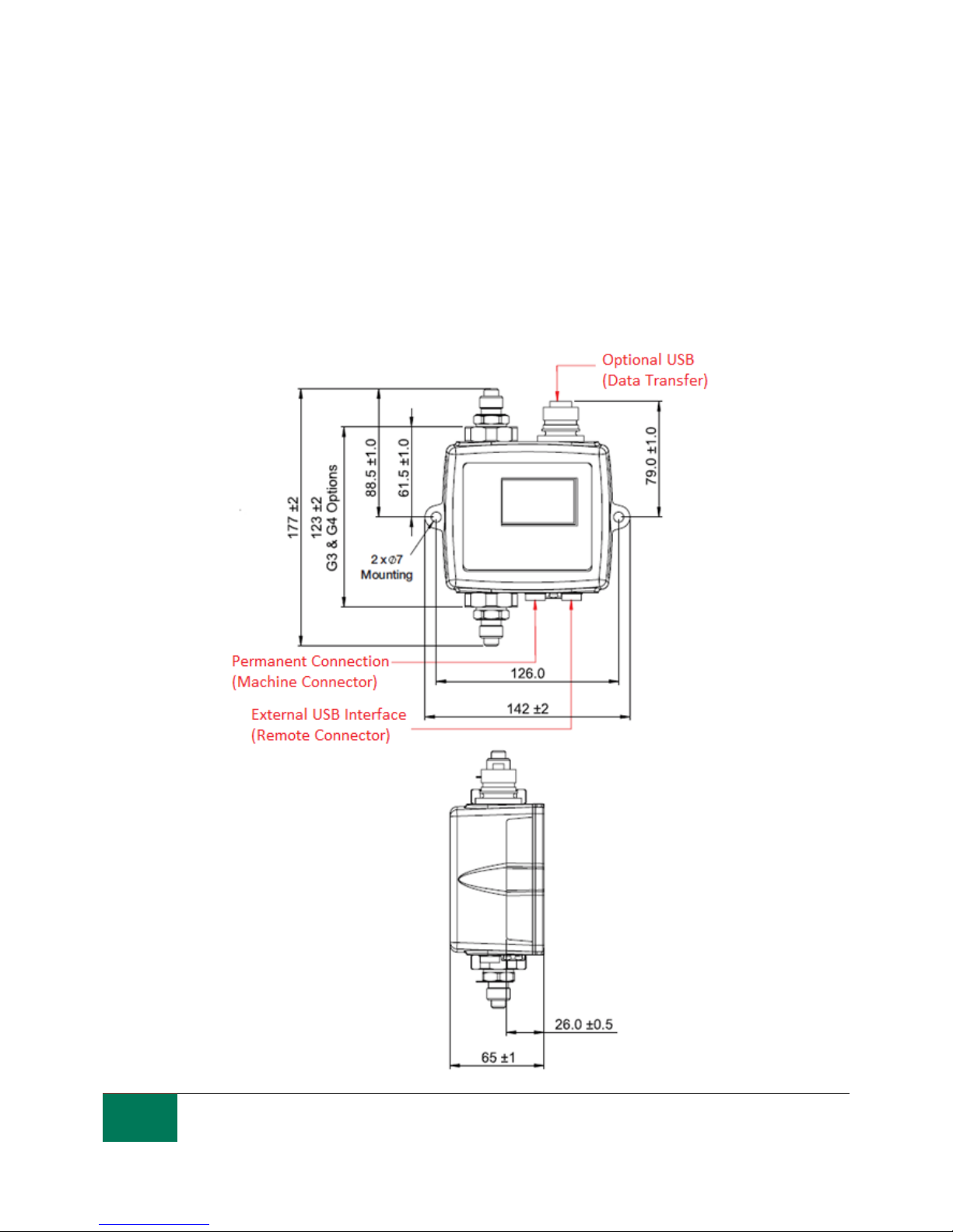
5.3 Physical Attributes
Dimensions 123mm (H) x 142mm (W) x 65mm (D)
Mounting 2 holes Ø7mm 126mm apart
Weight 1.6kg
Connections M16x2 hydraulic connection
Seal Material M/G Version –Viton (contact Stauff for any fluids that are incompatible with Viton
seals
E Version - Perfluoroelastomer

15
As a policy of continual improvement, STAUFF reserves the right to alter the specification without prior notice.
201.031 Date of Issue: 06 November 2018
5.4 Fluid Characteristics
Fluid compatibility M version - mineral oils, synthetic fluids and diesels
G version –water based/ subsea fluids & M version fluids
E version –Aerospace phosphate esters, Skydrols®
Viscosity ≤ 1000 cSt
Fluid temperature -25°C to +80°C
Operating Flow Rate20-400ml/min
Maximum Pressure 420barg static (For high frequency pressure pulse applications contact Stauff)
Differential PressureTypically 0.5bar
5.5 Environment
Ambient working temperature -25°C to 80°C non D version / -25°C to 55°C D version
IP Rating IP66
IK Rating IK04
5.6 Wetted Parts List
M version
G Version
E Version
Copper Alloy C46400
Stainless Steel
Stainless Steel
Stainless Steel
Sapphire (Al2O3)
Sapphire (Al2O3)
Sapphire (Al2O3)
Viton
Perfluoroelastomer
Viton
PTFE
PTFE
PTFE
EPDM
FR4

16
As a policy of continual improvement, STAUFF reserves the right to alter the specification without prior notice.
201.031 Date of Issue: 06 November 2018
6 Product Installation and General Operation
6.1 Installation
Each LPM supplied consists of the following:
LPM
Calibration certificate
USB Stick which includes: Product User Guides, LASPAC-View software, accessory product drivers
and product brochures
Pre-wired 3m cable
Quick Start Guides
Optional Equipment:
Circular connector pre-wired with 3m cable
LPMRDU2.0 Remote display unit
500μm coarse screen filter
LPM-DAV Flow Control Valve
LPMUSBInterface USB adaptor with pre-wired LPM cable
LPMETHInterface RJ-45 adaptor with pre-wired LPM cable
6.1.1 Physical Procedure
Decide on tapping points in hydraulic circuit
Locate the unit mechanically and bolt to desired location using fixing holes provided. The LPM must
be in a vertical orientation, with the oil flowing upwards through it
Wire back to junction box
Check flow in acceptable range. There needs to be a differential pressure of more than
approximately 0.5bar placed across the LPM, such that a flow of fluid is generated within the range
of the unit.
If there is no suitable differential pressure available, then a flow controller will be needed. One
solution is the LPM-DAV pressure compensated flow control valve. This limits the flow to around
200ml/minute for differential pressures up to 400bar. This should be fitted to the drain side of the
LPM (the top fitting).
Fix mechanically
Connect hoses or hard pipe from the system
−There must be no extra restriction placed in the drain hose. Do not have a pipe going to a
restrictor to control flow. Any such restrictor must be mounted directly to the LPM drain fitting. (A)
−Fluid flow must be from the bottom fitting to the top, following the direction of flow arrow on the
product labelling i.e. the bottom fitting is the inlet and the top fitting is the outlet.
Fit electrical connector, wire back to a junction box.
(A) This is because any length of pipe between the LPM and a downstream restrictor can act as an
accumulator. Any pressure pulsations (for example from a pump) in the feed to the LPM are then
translated into pulsations in flow rate, sometimes leading to flow reversals in time with the
pulsations. If the flow is very low this can sweep the same particle backwards and forwards
through the sensing volume multiple times, confusing the results.

17
As a policy of continual improvement, STAUFF reserves the right to alter the specification without prior notice.
201.031 Date of Issue: 06 November 2018
6.1.2 Electrical Interface
A separate LPM-USBInterface product is available for those wishing to have a simple plug and play
solution providing connection of the LPM to a computer. This section is for those wishing to do their own
wiring to the product.
6.1.2.1 Electrical Connectors
The LPM has two circular connectors located on the lower face of the unit. The USB Interface product
can be connected to either one depending on the installation configuration, see figure 6.1.
Pin
Colour
“Machine” Connector
“Remote” Connector
1
Yellow
RS485+/CANL/4-20mA(A)
RS485+
2
Pink
START INPUT
3
Green
RS485-/CANH/4-20mA(B)
RS485-
4
White
OUTPUT 1
5
Grey
I/O COMMON
6
Brown
OUTPUT 2
7
Blue
DC 0V
DC 0V
8
Red
DC +POWER
DC +POWER
6.1.2.1.1 Remote Connector
The “remote connector” is intended for temporary connection of an external communication device e.g.
LPMUSBInterface so as to allow data download, remote control or diagnostics using the LASPAC-View
software.
This is the circular connector furthest from the hydraulic connection, see figure 6.1.
This carries RS485 data and can also be used to power the unit temporarily in the event of a system
being shut down, thus no longer providing power to the unit.
This connector doesn’t send alarm signals as shown in the wiring diagram 6.7. If you require a USB
Interface to send alarm signals it has to be connected to the machine connector.
6.1.2.1.2 Machine Connector
The “machine connector” is intended for permanent connection to the PLC / machine that powers the
LPM during normal operation. It has power connections, a start signal input, two relay outputs, and a
data pair that can be set to RS485, CANbus or 4-20mA signaling modes.
This is the circular connector closest to the hydraulic connection, see figure 6.1.
NOTE: If CANBUS or 4-20mA option has been selected, standard communication with an RS485
adapter (e.g. USB Interface) on this port is no longer available.
The right hand port (remote connector) should be used if temporary connection is required.
NOTE: Start signal and relay outputs only apply to this connector.

18
As a policy of continual improvement, STAUFF reserves the right to alter the specification without prior notice.
201.031 Date of Issue: 06 November 2018
Figure 6.1 Connector Orientation
Figure 6.2 Machine Connector External Wiring Example
6.1.2.2 DC Power
DC power is connected to pins 7 and 8 of either circular connector (Red and Blue if using the pre-wired
cable). All the other signals are optional.
Item
Minimum
Maximum
Voltage
9V DC
36V DC
Current
200mA

19
As a policy of continual improvement, STAUFF reserves the right to alter the specification without prior notice.
201.031 Date of Issue: 06 November 2018
6.1.2.3 Machine Connector - Serial Interface
An RS485 or CANbus interface can optionally be connected to pins 1 and 3 (yellow and green). This can
be a PLC running customer software, or a PC with a RS485 adaptor running the supplied LASPAC-View
software. To provide a reference the RS485 0V connection should also be linked to the LPM 0V (as
shown on figure 6.3).
The standard LPM control protocol is Modbus RTU. Modbus is a freely available open standard for
industrial control. Adapters are available to interface to other industrial control busses. The standard
LASPAC-View software from Stauff itself uses Modbus to communicate with the LPM, but it is also
possible for customers to implement their own controllers (section Modbus).
The CANbus protocol can also be used, see separate LPM-CANbus manual.
Figure 6.3a PC Control Example
Figure 6.3b Modbus Controller Example
Figure 6.3a shows a single LPM linked to a PC, using a USB-RS485 adaptor. Figure 6.3b shows a
slightly different method. 100 Ohm termination resistors should be fitted as shown for long cables, for
example over 10m. Twisted pair wiring should be used for any length over 2m.
Table of contents
Other STAUFF Measuring Instrument manuals


