– 12 – – 13 –
GB
GB
1. About this document
Please read carefully and keep in a safe place.
– Under copyright. Reproduction either in whole or
in part only with our consent.
– Subject to change in the interest of technical
progress.
Symbols
!Hazard warning!
... Reference to other information in the
document.
2. General safety precautions
!Disconnect the power supply before
attempting any work on the unit.
šInstalling these units involves work on the mains
voltage supply; installation must therefore be
carried out professionally in accordance with
the applicable national wiring regulations and
electrical operating conditions (DE-VDE 0100,
AT-ÖVE/ÖNORM E 8001-1, CH
-SEV 1000)
šThe light must be positioned so that it is not
expected that anybody can stare into the light
for any prolonged period from a distance of less
than 0.3 m.
š The floodlight enclosure heats up when the light
is on. Only adjust the angle of the LED panel
once it has cooled down. Do not look into the
LED light at short range or for any prolonged
period (> 5 min). You could damage your retina.
šDo not install the unit on (normally) flammable
surfaces.
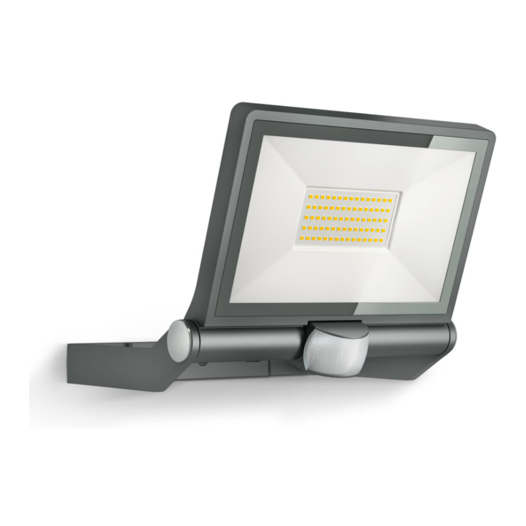
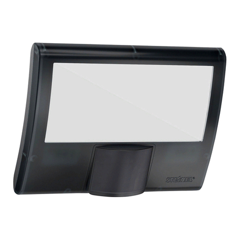
3. XLED home 2 / XLED home 2 XL
Proper use
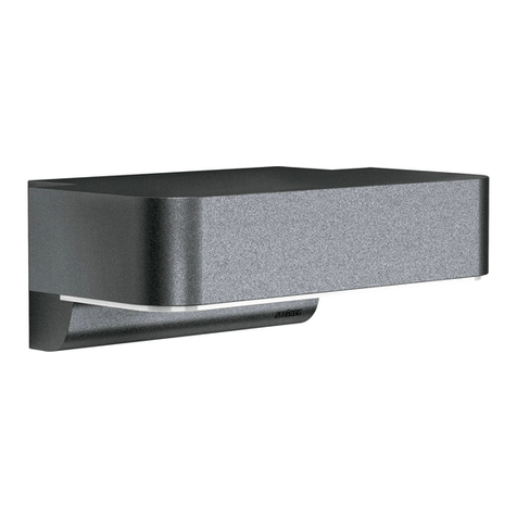
– Sensor-switched floodlight suitable for wall
mounting outdoors.
– Fully swivelling LED panel and moveable sensor.
– Available as a standalone floodlight or intercon-
nected with the slave version.
Movement triggers lights, alarms and many
other devices. With the fully swivelling panel, the
floodlight can be used at home to provide perfect
illumination for lighting up property, or commercially
for lighting up business premises. In conjunction
with the opal cover, this extremely e"cient technol-
ogy provides wide-area lighting.
Models
– XLED home 2
– XLED home 2 XL
Package contents (Fig. 3.1)
Sensor adjustment range (Fig. 3.2 / 3.3 / 5.6)
Product dimensions (Fig. 3.4 / 3.5)
Product components (Fig. 3.6)
A LED panel
B Enclosure
C Wall mount
D Sensor unit
E Twilight setting
F Time setting
4. Electrical installation
š Switch OFF power supply (Fig. 3.7)
Connecting the mains power supply lead
The supply lead consist of three wires:
L = phase conductor (usually black, brown or grey)
N = neutral conductor (usually blue)
PE = protective-earth conductor (green/yellow)
If you are in any doubt, identify the conductors
using a voltage tester; then disconnect from the
power supply again. Connect the phase conductor
(L) and neutral conductor (N) to the terminal block.
The protective-earth conductor can be looped
through by means of terminal (E).
Wiring diagram (Fig. 3.7)
Important:
Incorrectly wired connections will produce a short
circuit later on in the product or your fuse box. In
this case, you must identify the individual conduc-
tors once again and re-connect them.
The light source of this luminaire cannot be
replaced. If the light source needs to be replaced
(e.g. at the end of its service life), the complete
luminaire must be replaced.
5. Mounting
šCheck all components for damage.
šDo not use the product if it is damaged.
šSelect an appropriate mounting location, taking
the reach and motion detection into considera-
tion. (Fig. 4.1)
Ř $LPLQJWKHVHQVRUVZLWFKHGƃRRGOLJKW (Fig. 4.4)
The most reliable motion detection is achieved
by mounting the unit to face across the direc-
tion in which people walk and by making sure no
obstacles (e.g. trees, walls etc.) interrupt the line of
sensor vision (Fig. 4.2 / 4.3).
Mounting procedure
šSwitch OFF power supply. (Fig. 3.7)
šUndo retaining screws. (Fig. 4.5)
šDetach enclosure (B) from wall mount (C).
(Fig. 4.6)
šDetach plug-in terminal (male) from wall mount.
(Fig. 4.7)
šMark drill holes. (Fig. 4.8)
šDrill holes and fit wall plugs. (Fig. 4.9)
šFit sealing plug. (Fig. 4.10)
– Power supply lead, concealed. (Fig. 4.11)
– Power supply lead, surface-mounted,
with spacers. (Fig. 4.12)
šConnect conductors. (Fig. 4.13)
šConnect plug-in terminal. (Fig. 4.14)
šFit enclosure onto wall mount. (Fig. 4.15)
šScrew in retaining screw. (Fig. 4.16)
šSwitch ON power supply. (Fig. 4.16)
šMake settings « "6. Function"
6. Function
Factory settings for control dials
Twilight setting (E): 2000 lux
Time setting (F): 8 s
Twilight setting (Fig. 5.1 / E)
LQƂQLWHO\YDULDEOH
Control dial set to
= twilight operation,
approx. 2 lux
Control dial set to
= daylight operation,
approx. 2000 lux.
Note:
To adjust the detection zone in daylight, the control
dial must be set to = daylight operation.
Time setting (Fig. 5.1 / F)
Control dial set to max = longest time,
approx. 35 min
Control dial set to min = shortest time,
approx. 8 s
Note:
When setting the detection zone, we recommend
selecting the shortest time.
Reach setting/adjustment
The detection zone can be optimised to suit
requirements.
Sensor unit
– Sensor unit swivels through 180°. (Fig. 5.3)
– Sensor unit tilts through 90°.( Fig. 5.6)
Adhesive shrouds (Fig. 5.4)
The film shroud can be used for masking out any
number of lens segments to limit reach as required.
Inadvertent triggering is ruled out or the sensor can
be targeted to watch over danger spots (Fig. 5.5).
Other information:
Floodlight adjustment range (Fig. 3.2 / 3.3 / 5.2)
7. Operation / maintenance
The unit is not suitable for burglar alarm systems
as it is not tamperproof in the manner prescribed
for such systems. Weather can a%ect operation of
the sensor-switched LED floodlight. Strong gusts
of wind, snow, rain and hail may cause the light
to come ON when it is not wanted because the
sensor is unable to distinguish between sudden
changes in temperature and sources of heat.
The detector lens may be cleaned with a damp
cloth if it gets dirty (do not use cleaning agents).
8. Disposal
Electrical and electronic equipment, accessories
and packaging must be recycled in an environmen-
tally compatible manner.
Do not dispose of electrical and electronic
equipment as domestic waste.
EU countries only:
Under the current European Directive on Waste
Electrical and Electronic Equipment and its imple-
mentation in national law, electrical and electronic
GB
