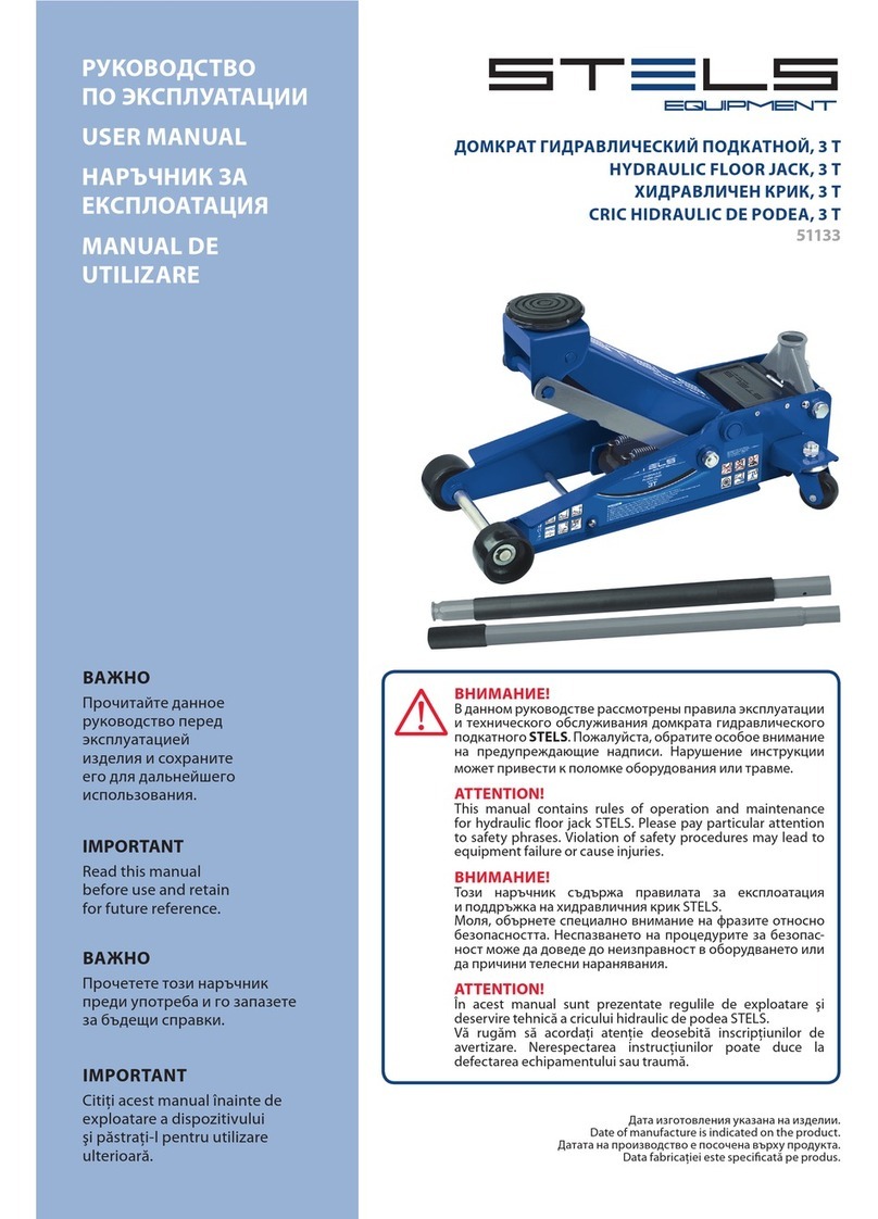
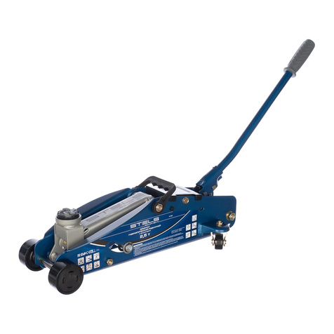
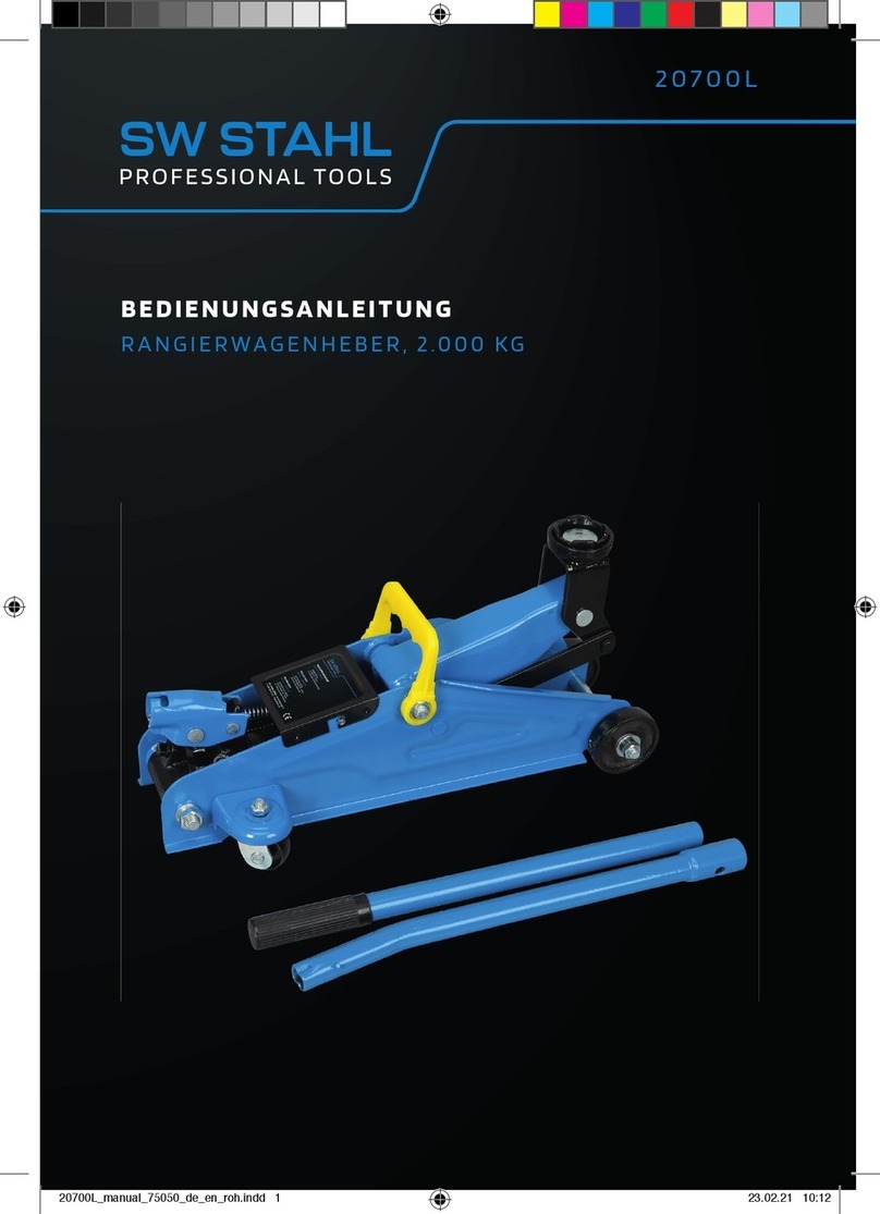
Stels 51135 User manual

USER MANUAL
MANUAL
DE INSTRUÇÃO
51135
IMPORTANT
Read this manual
before use аnd retain
for future reference.
IMPORTANTE
Leia este manual antes
de usar e guarde para
referência futura
Прочитайте данное
руководство перед
эксплуатацией
изделия и сохраните
его для дальнейшего
использования.
!
В данном руководстве рассмотрены правила экс-
плуатации и технического обслуживания домкрата
гидравлического подкатного STELS.
Пожалуйста, обратите особое внимание на пре-
дупреждающие надписи. Нарушение инструкции
может привести к поломке оборудования или травме.
ATTENTION!
Thismanualcontainsrulesofoperationandmaintenance
for hydraulic oor jack STELS.
Please pay particular attention to safety phrases.
Violation of safety procedures may lead to equipment
failure or cause injuries.
ATENÇÃO!
Este manual contém regras de funcionamento e
manutenção para o macaco hidráulico de pavimento
STELS.
Preste atenção às frases de segurança. A violação dos
procedimentos de segurança pode levar à falha do
equipamento ou causar lesões.
HYDRAULIC FLOOR JACK, 3.5 T
MACACO HIDRÁULICO TIPO JACARÉ, 3.5 T
, 3,5
Date of manufacture is indicated on the product.
A data de fabricação é indicada no produto.
Дата изготовления указана на изделии.

Hydraulic floor jack
2
eng
CONTENTS
PURPOSE OF THE ITEM.................................................................................................................. 3
DELIVERY SET.................................................................................................................................... 3
TECHNICAL CHARACTERISTICS................................................................................................. 3
COMPONENTS .................................................................................................................................. 4
SAFETY INSTRUCTIONS................................................................................................................ 4
BEFORE USE ....................................................................................................................................... 5
JACK OPERATING PROCEDURE ................................................................................................. 5
MAINTENANCE................................................................................................................................. 6
TROUBLESHOOTING CHART....................................................................................................... 7
PREPARATION TO UTILIZATION................................................................................................. 7
SELLING AND UTILIZATION......................................................................................................... 7
TRANSPORTATION.......................................................................................................................... 8
STORAGE............................................................................................................................................. 8
WARRANTY PERIOD ...................................................................................................................... 8
WARRANTY ........................................................................................................................................ 8
SERVICE LIFE PERIOD ..................................................................................................................... 8
DATE OF MANUFACTURE............................................................................................................. 8
IMPORTER........................................................................................................................................... 8

3
USER MANUAL
eng
PURPOSE OF THE ITEM
DELIVERY SET
1 2 3
1. Jack, 1 pc
2. Handle, 1 pc (consists of two parts
3. User manual
TECHNICAL CHARACTERISTICS
PRO
FOR
PROFESSIONAL
USE
LOW
PROFILE
QUICK
LIFT
min mm
max mm
Characteristics 51135
Lifting capacity, t 3.5
Pickup height, mm 100
Lifting height, mm 565
Item gross weight, kg 46
Handle length, mm 1200
Oil type Machine oil 22
Oil working volume, ml 265
Temperature working range, ˚С −25…+45

Hydraulic floor jack
4
eng
COMPONENTS
3
2
5
1
12
13
9
8
10
6
11
7
4
1. Frame
2. Lifting arm
3. Saddle (support base)
4. Handle
5. Tray
6. Front wheels
7. Real wheels
8. Hydraulic unit
9. Safety valves
10. Oil ller
11. Lubrication tting
12. "QUICK LIFT" system
13. Base
SAFETY INSTRUCTIONS
The dolly-type jack is high hazard equipment.
To avoid the risk of injuries and damage to property, read these operating instructions completely and
familiarize yourself thoroughly with the product.
This jack may be used only for load lifting. Never use this jack for the raised load pulling. Pulling of the jack
with lifted load is prohibited.
This jack should be used only on smooth, hard and level surface capable of sustaining the load. Use on
other surface may cause load to drop.
After lifting, the load should be xed with the help of special props or supports designed to hold the rated

5
USER MANUAL
eng
load weight and reliably keeping it in the lifted position.
It is prohibited to stay or carry out works under the lifted load held only by the jack. Stay away from moving
hinged joints of the jack.
Never exceed the maximum rated lifting capacity of the jack. Overload of the jack may result in its failure
and cause personal injury.
The safety valve is adjusted for safe operation of the item with maximum rated load of 3.5 tons. It is
prohibited to change factory settings of the safety valve on your own; it may cause failure of the item and
personal injury.
It is permitted to use only the components and adapters recommended for use by the manufacturer.
It is prohibited to disassemble the jack on your own initiative, as well as make changes into the construction
of the jack.
Failure to heed these rules may result in causing personal injury and failure of hydraulic equipment.
The operator working with the jack should be cautious, competent, should have passed a training course
and have a qualication in safety techniques when working with servo motors and their moving parts,
and should preserve safety measures while operating the jack.
All warning labels should always be legible and these operating instructions should be kept intact during
the whole service life of the jack.
BEFORE USE
Assemblethehandle ofthejackpump.Inserttheupper part ofthehandle intothelower part, align the holes
in them and insert the xing screw by tightening it with the nut.
Install the handle assembly into the base and make sure that it is reliably xed in the slot; and then tighten
it with the bolt. Try to rotate the handle in both directions – it should move freely.
Test the jack. For this, turn the handle clockwise until the release valve is rmly closed. Pump handle several
times up and down; when this is done, the lifting arm of the jack should start rising. To lower the lifting arm,
turn the release valve with the help of the handle counterclockwise by no more than three turns. When the
lifting arm is lowered completely, close the release valve by turning its handle clockwise as far as it goes.
2 31
JACK OPERATING PROCEDURE
THROUGH THE EXAMPLE OF VEHICLE LIFTING
Make sure that the vehicle and jack are on smooth and hard surface and the jack has a possibility to be
displaced during lifting and lowering of the vehicle. Uneven, soft or slanted surfaces create hazard for the
execution of works.
Apply the parking brake in the vehicle, turn the automatic gearbox selector into the Р position or engage

Hydraulic floor jack
6
eng
the rst gear in the vehicles with the mechanical gearbox; place vehicle wheels for straight-driving direction.
Additionally, x the wheels which are not planned to be raised from the ground with wedge chocks. Make
sure that the vehicle passenger compartment is free of passengers.
With the help of the vehicle instruction manual, determine the points in the car body that may be used for car
lifting by the jack. Install the jack with fully lowered lifting arm under the vehicle opposite the vehicle lifting
point designed to contact jacks.
Close the release valve with the help of the jack handle by turning it clockwise as far as it goes, then insert
the handle into the pump unit handle sleeve and slowly pump until the lifting arm of the jack touches the
lifting point in the vehicle designed to contact jacks.
Check position of the lifting arm saddle of the jack. Make sure that:
1. The lift point in the vehicle body is positioned exactly against the center of the saddle;
2. The vehicle may not slip o the jack;
3. The lifting arm of the jack will not damage any parts and components of the vehicle.
Lift the vehicle to the required height by pumping the handle of the jack. Install special stands or props under
the body of the vehicle.
Slowly turn the release valve by rotating the handle counterclockwise until the vehicle starts lowering
on the props. Make sure that the props are reliably holding the elevated vehicle.
Prior to lowering the vehicle after nishing the operations, make sure that there are no people or foreign
objects under the vehicle.
Screw the handle of the jack by rotating it clockwise as far as it goes, then slowly pump it until the lifting arm
of the jack touches the vehicle lifting point designed to contact jacks.
Check position of the lifting arm saddle of the jack. Make sure that:
1. The lift point in the vehicle body is positioned exactly against the center of the saddle;
2. The vehicle may not slip o the jack;
3. The lifting arm of the jack will not damage any parts and components of the vehicle.
Raise the vehicle a little by pumping the handle of the jack so as to remove the supports from under it. Remove
the supports to the side so that they permit the vehicle to rest on its wheels.
Slowly turn the handle of the jack counterclockwise until the vehicle starts lowering. Take care that the vehicle
is lowering slowly and smoothly.
After the vehicle is fully lowered on its wheels and is stable, wait until the lifting arm of the jack goes
o from the lift pointofthevehicle. Then roll the jack aside and closethe releasevalve byrotatingthehandle
of the jack clockwise until it is fully closed.
MAINTENANCE
When the jack is not used, the lifting arm of the jack should be fully lowered. This will prevent rusting
of the lifting arm piston rod.
Periodically lubricate moving parts of the jack: lifting arm piston rod, pump rods, axles and bearings
of the wheels. Use any engine oil for the purpose. Provision is made to lubricate the axle of the lifting arm
through a special lubrication nipple.
Do not use gasoline, kerosene, solvents and abrasive substances for cleaning the jack. They may damage
rubber seals and cause oil leakage.
Store jack on level surface in a clean and dry place. When doing so, see that the lifting arm of the jack is fully
lowered, and the release valve is fully closed.
The repairoftheitemshouldbeperformedonly byhighlyqualied specialistsof theservicingcenter.Thelist
of service centers is presented in the warranty card.

7
USER MANUAL
eng
TROUBLESHOOTING CHART
Symptom Possible cause Corrective action
Jack will not lift or
lower load Insucient oil level
Check oil level as per the following instructions:
1. Turn the release valve counterclockwise so that the piston
goes down fully. If the lifting arm does not go down, use force.
2. Place jack in a vertical position, open oil ller plug. Oil level
should be at the level of the lower point of the ller hole.
If the oil level is lower, top up oil to the required level. Use only
recommended type of oil.
3. Return the oil ller plug back home.
4. Close the release valve and lift fully and lower the lifting arm
of the jack several times. This will help fully distribute oil
in the whole system. In most cases, this helps to restore
the serviceability of the item.
5. Check operation of the jack.
Air is trapped in the
system of the jack
1. Turn the release valve counterclockwise by one full turn and
make six full strokes with the handle.
2. Turn the release valve clockwise as far as it goes
so as to close it fully.
3. Continue to pump the pump with the handle until the lifting
arm occupies the upper position and pump handle several
more strokes so as to blow all the air from the piston.
4. Carefully open oil ller plug partially so as to release
the trapped air.
5. Turn the release valve counterclockwise by one full turn;
lower the lifting arm to the extreme low position. Use force,
if necessary.
6. Close the release valve clockwise as far as it goes and check
serviceability of the jack. If necessary, repeat the above-
mentioned procedure one more time.
Jack will not lower
fully
The return spring of
the lifting arm has
slipped o or is broken
Drive it home or replace.
Lubricate all moving parts of the lifting arm.
Oil level is too high Check oil level and drain excess by opening the oil ller plug.
PREPARATION TO UTILIZATION
Prior to utilization of the item all working uid should be drained from it. To do this, turn the release valve
counterclockwise so that the piston goes full way down, and then close the valve. Open the oil ller plug
and drain all the oil.
SELLING AND UTILIZATION
The STELS equipment is realized via sales outlets and shops in accordance with the legislature of the
Russian Federation. Utilization of STELS equipment is performed in accordance with the requirements
and norms
of Russia and countries — participants of the Customs Union.

Hydraulic floor jack
8
eng
TRANSPORTATION
Item can be forwarded by all types of enclosed transport in accordance with shipping rules, applicable for
each type of transport.
Transportation conditions under climatic factors:
outdoor temperature from -20 to +55 °С;
relative humidity up to 80 % under temperature +20 °С.
The package with item should not subjected to excessive shocks and precipitation during transportation
and handling.
Stowage and securing the transport crate with the packaged item in vehicles should ensure a stable
position and the lack of ability to move during transportation.
STORAGE
Storage must be carried out at outdoor temperatures from 0 to +40 ° C and relative humidity less than
80%, out of the reach of children. Shelf life is unlimited.
WARRANTY PERIOD
The warranty period of the item makes up 12 months since the date of selling, provided the safety rules,
rules of operation with the item and servicing and storage conditions have been duly preserved. The
consumer has the right to address the service center (see the warranty card) for post-warranty servicing
or repair.
WARRANTY
Product manufacturer's warranty is applied to the item.
Warranty period specied in the warranty card, and calculated from the date of sale. Warranty rules can
be found in warranty card.
SERVICE LIFE PERIOD
Average service life period subject to the rules of operation by consumer is 5 years.
DATE OF MANUFACTURE
The date of manufacture stamped on the product as item code:
TH22010 20140315 0001
1 2 3
1. Model (original article) of manufacturer
2. The date of manufacture in the format of "year / month / day"
3. Lot number
IMPORTER
Address and contact telephone of the authorized importer organization: OOO «MIR INSTRUMENTA»
117588, city of Moscow, P.O. Box 70, tel.: +7 (495) 2344130 .
Made in PRC

9
POr
MANUAL DE INSTRUçãO
ÍNDICE
OBJETIVO DO ITEM....................................................................................................................... 10
CONJUNTO DE ENTREGA........................................................................................................... 10
CARACTERÍSTICAS TÉCNICAS..................................................................................................10
COMPONENTES.............................................................................................................................. 11
INSTRUÇÕES DE SEGURANÇA.................................................................................................. 11
ANTES DE USAR.............................................................................................................................. 12
MACACO PROCEDIMENTO OPERACIONAL......................................................................... 12
MANUTENÇÃO ............................................................................................................................... 13
TABELA DE SOLUÇÃO DE PROBLEMAS ................................................................................ 13
PREPARAÇÃO PARA UTILIZAÇÃO ........................................................................................... 14
ARMAZENAMENTO....................................................................................................................... 15
PERÍODO DE GARANTIA ............................................................................................................. 15
GARANTIA ........................................................................................................................................ 15
GARANTIA DE SERVIÇO DO PRODUTO................................................................................. 15
DATA DE FABRICAÇÃO ................................................................................................................ 15
IMPORTADOR.................................................................................................................................. 15

MACÁCO HIDRULICO TIPO JACARÉ
10
POR
OBJETIVO DO ITEM
COMPONENTES NA ENTREGA
1 2 3
1. Macaco Hidrálico, 1 peça
2. Alavanca, 1 peça (contém duas partes)
3. Manual de instrução
CARACTERÍSTICAS TÉCNICAS
PRO
FOR
PROFESSIONAL
USE
LOW
PROFILE
QUICK
LIFT
min mm
max mm
Characteristics 51135
Capacidade de Elevação, t 3,5
Altura da haste, mm 100
Altura total com a haste, mm 565
Peso bruto, kg 46
Comprimento da alavanca, mm 1200
tipo de óleo Óleo de máquina 22
Volume de óleo, ml 265
Escala de trabalho Temperatura, C −25…+45

11
MANUAL DE INSTRUçãO
POr
COMPONENTES
3
2
5
1
12
13
9
8
10
6
11
7
4
1. Quadra
2. Braço de Elevação
3. Base de apoio
4. Cabo de alavanca
5. Bandeja
6. Rodas dianterias
7. Rodas traseiras
8. Comando hidráulico
9. A válvula de segurança
10. Abastecimento de óleo
11. Sistema de lubricação
12. Sistema de Elevação rapido
13. Base
INSTRUÇÕES DE SEGURANÇA
O macaco hidráulico é um equipamento de perigo elevado. Para evitar o risco de ferimentos e danos à
propriedade, leia este manual de instruções completamente e familiarizar-se completamente com o
produto. Este macaco pode ser usado apenas para elevação de carga. Nunca puxar o macaco com carga
levantada é proibida. Este macaco deve ser usado somente piso plano, resistentes e superfície nivelada
capaz de sustentar a carga. Uso em outra superfície pode causar a queda da carga. Após o levantamento, a
carga deve ser xada com a ajuda de adereços especiais ou suportes concebidos para suportar o peso da
carga nominal e mantê-lo de forma conável na posição levantada.

MACÁCO HIDRULICO TIPO JACARÉ
12
POR
É proibido car ou realizar obras ao abrigo da carga levantada realizada apenas pelo macaco. Fique longe
de se mover junto ao macaco.
Não exceder a capacidade máxima de elevação do macaco. A sobrecarga pode resultar em sua falha e
causar ferimentos.
O macaco hidráulico suportar uma carga máximo de 3 toneladas. É proibido alterar as congurações de
fábrica da válvula de segurança; pode causar a falha ou ferimentos pessoais.
É permitido utilizar apenas os componentes e adaptadores recomendadas pelo fabricante. É proibido
desmontar o macaco, bem como fazer alterações na sua estrutura.
O operador que trabalha com o macaco deve ser cauteloso, competente, deve ter feito um curso de
formação e ter uma qualicação em técnicas de segurança ao trabalhar com setores de motores e suas
partes móveis e deve preservar as medidas de segurança durante o funcionamento do macaco.
Todas as etiquetas de advertência devem ser sempre legíveis e estas instruções de funcionamento devem
ser mantidas intactas durante toda a vida útil do macaco.
O não cumprimento destas regras pode resultar em ferimentos pessoais e falhas no equipamento hidráulico.
ANTES DE USAR
Montar o punho da bomba do macaco. Insira a parte superior do punho na parte inferior, alinhe os furos
neles e insira o parafuso de xação apertando-o com a porca.
Instale o conjunto do punho na base e se certicar de que ela está xada de forma conável. E depois
aperte-o com o parafuso. Tente girar o cabo em ambas as direções - ele deve se mover livremente.
Realizando texto macaco. Para isso, gire a alavanca no sentido horário até que a válvula de liberação que
rmemente fechada. Movimente a bomba várias vezes para cima e para baixo; quando isso é feito, o braço
de elevação do macaco deve começar a subir. Para abaixar o braço de elevação, gire a válvula de liberação
com a ajuda do punho no sentido anti-horário por não mais de três voltas. Quando o braço de elevação
é abaixado completamente, feche a válvula de liberação girando sua alavanca no sentido horário até
onde ela for.
PROCEDIMENTO OPERACIONAL
THROUGH THE EXAMPLE OF VEHICLE LIFTING
Certique-se de que o veículo e o macaco estão em superfície lisa e resistente e ser o macaco tem a
possibilidade de ser deslocado durante a elevação e abaixamento do veículo. As superfícies irregulares ou
inclinadas criam riscos para a execução do trabalho.
Acione o freio de mão do veículo, no caso de carro automáticos mantenha na posição Р ou engate a primeira
marcha nos veículos com direção mecânica; Colocar as rodas do veículo na direção reta.
Além disso, xar as rodas que não são planejadas para ser levantado do chão com calços de cunha. Certique-
se de que não há passageiros dentro do veículo.
Com a ajuda do manual de instruções do veículo, determinar os pontos na carroçaria do automóvel que
pode ser utilizado para o levantamento do carro pelo macaco. Instale o macaco com o braço de elevação
totalmente rebaixado sob o veículo em frente ao ponto de elevação do veículo concebido para contato do

13
MANUAL DE INSTRUçãO
POr
macaco.
Feche a válvula de libertação com o auxílio da alavanca do macaco, rodando-a no sentido horário até ao
m, insira o manípulo na manga da pega da bomba e bombear lentamente até que o braço de elevação do
macaco toque o ponto de elevação do veículo concebido para Tomadas de contato.
Verique a posição do suporte do braço de elevação do macaco. Certique-se de que:
1. O ponto de elevação do veículo é posicionado corretamente no centro;
2. O veículo não pode deslizar sobre a base de apoio do macaco;
3. O braço de elevação do macaco não irá causar danos há nenhuma peça do veículo.
Levante o veículo à altura necessária, bombeando o cabo do macaco. Instale suportes especiais ou acessórios
sob o corpo do veículo.
Gire lentamente a válvula de liberação, é girando a alavanca no sentido anti-horário até que o veículo comece
a baixar nos adereços. Certique-se de que os apoios estão segurando o veículo elevado.
Antes de baixar o veículo após o término das operações, verique se não há pessoas ou objetos sob o veículo.
Coloque a alavanca do macaco rodando-a no sentido horário até ao ponto em que se encontra e, em seguida,
bata-a lentamente até que o braço de elevação do macaco toque o ponto de elevação do veículo concebido
para contato do macaco.
Depois que o veículo estiver completamente baixado sob as rodas e estável, aguarde até que o braço de
elevação do macaco que fora do ponto de elevação do veículo. Em seguida, role o macaco de lado e feche
a válvula de liberação, girando o punho do macaco no sentido horário até que esteja completamente
fechado.
MANUTENÇÃO
Quando o macaco não for utilizado, o braço de elevação do macaco deve estar totalmente baixado. Isso
impedirá que haja ferrugem na haste do pistão e braço de elevação.
Periodicamente lubricar as peças móveis do macaco: haste do pistão do braço de elevação, hastes da
bomba, eixos e rolamentos das rodas. Use qualquer óleo do motor para o efeito. É feita uma provisão para
lubricar o eixo do braço de elevação através de um bocal especial de lubricação.
Não utilize gasolina, querosene, solventes e substâncias abrasivas para limpar o macaco. Eles podem
danicar as vedações de borracha e causar vazamento de óleo.
Guarde o macaco na superfície nivelada num local limpo e seco. Ao fazer isso, verique se o braço de
elevação do macaco está completamente abaixado e a válvula de liberação está completamente fechada.
A reparação do artigo deve ser realizada apenas por especialistas altamente qualicados do centro de
serviço. A lista de centros de serviço é apresentada no cartão de garantia.

MACÁCO HIDRULICO TIPO JACARÉ
14
POR
TABELA DE SOLUÇÃO DE PROBLEMAS
CAUSA POSSÍVEIS CAUSA AÇÃO CORRETIVA
O macaco não
levanta ou abaixa
a carga
Nível de óleo
insuciente
Verique o nível de óleo conforme as instruções a seguir:
1. Gire a válvula de liberação no sentido anti-horário para que
o pistão desça completamente. Se o braço de elevação não
descer, use força.
2. Coloque o macaco na posição vertical, abra o tampão de
enchimento de óleo. O nível de óleo deve estar ao nível do
ponto mais baixo do orifício de enchimento. Se o nível de óleo
for menor, encha o óleo até o nível desejado. Utilize apenas o
tipo de óleo recomendado.
3. Retorne o tampão de enchimento de óleo.
4. Feche a válvula de liberação e levante-a completamente
e abaixe o braço de elevação do macaco várias vezes. Isso
ajudará a distribuir
5. Em todo o sistema. Na maioria dos casos, isso ajuda a
restaurar a capacidade de manutenção do item.
6. Verique o funcionamento do macaco.
O ar está preso no
sistema hidráulico
1. Gire a válvula de liberação no sentido anti-horário por uma
volta completa e faça seis cursos completos com a alça
2. Gire a válvula de liberação no sentido horário até o m para
fechá-la completamente.
3. Continue a bombear a bomba com a pega até que o braço
de elevação ocupe a posição superior ea manivela da bomba
várias vezes mais para soprar todo o ar do pistão.
4. Abra cuidadosamente o tampão de enchimento de óleo
parcialmente para libertar o ar.
5. Gire a válvula de liberação no sentido anti-horário em uma
volta completa; abaixe o braço de elevação até a posição mais
baixa. Use força, se necessário.
6. Feche a válvula de liberação no sentido horário até o m
e verique a capacidade de manutenção do macaco. Se
necessário, repita o procedimento acima uma vez mais.
Macaco não
vai baixar
completamente
A mola de retorno
do braço de
elevação desliza ou
está quebrada
Dirija-o para substituir.
Lubrique todas as partes móveis do braço de elevação.
O nível de óleo está
muito alto Verique o nível de óleo e drenar o excesso abrindo o tampão
de enchimento do óleo.
PREPARAÇÃO Á UTILIZAÇÃO
Antes da utilização do item todo o uido de trabalho deve ser drenado a partir dele. Para fazer isso, gire a
válvula de liberação no sentido anti-horário para que o êmbolo que cheio, e então feche a válvula. Abra
o tampão de enchimento de óleo e drene todo o óleo.
TRANSPORTE
O produto pode ser encaminhado por todos os tipos de transporte fechado de acordo com as regras de
expedição, aplicáveis para cada tipo de transporte.
Condições de transporte sob fatores climáticos: Temperatura exterior de -20 a +55 ° C;

15
MANUAL DE INSTRUçãO
POr
Humidade relativa até 80% sob temperatura +20 ° C.
O pacote com o item não deve ser submetido a choques excessivos e precipitação durante o transporte
e manuseio.
ARMAZENAMENTO
O armazenamento deve ser efeituado a temperaturas exteriores de 0 a +40 ° C e humidade relativa inferior
a 80%, fora do alcance das crianças. A vida útil é ilimitada.
PERÍODO DE GARANTIA
O período de garantia do item compensa 12 meses desde a data de venda, desde que as regras de
segurança, as regras de operação com o item e as condições de manutenção e armazenamento tenham
sido devidamente preservadas. O consumidor tem o direito de dirigir-se ao centro de assistência técnica
(ver o cartão de garantia) para assistência pós-garantia ou reparação.
GARANTIA
A garantia do fabricante do produto é aplicada ao item.
Período de garantia especicado no cartão de garantia e calculado a partir da data de venda. As regras de
garantia podem ser encontradas no cartão de garantia.
GARANTIA DE SERVIÇO E PRODUTO
Prazo de vida útil médio sujeito às regras de operação por consumidor é de 5 anos.
DATA DE FABRICAÇÃO
A data de fabricação carimbada no produto como código do item:
TH22010 20140315 0001
1 2 3
1. Modelo (artigo original) do fabricante
2. A data de fabricação no formato "ano / mês / dia"
3. Número do lote
IMPORTADOR
MUNDO DAS FERRAMENTAS DO BRASIL LTDA, RUA IRAQUARA, 18 GUARULHOS – SP, CEP: 07161-550,
TELEFONE: 11 2466-8086, SAC: 0800 777 8 999, mail@toolsworld.com.br
PAIS DE ORIGEM: CHINA

Домкрат гиДравлический поДкатной
16
RUS
НАЗНАЧЕНИЕ ИЗДЕЛИЯ............................................................................................................ 17
КОМПЛЕКТ ПОСТАВКИ.............................................................................................................. 17
ТЕХНИЧЕСКИЕ ХАРАКТЕРИСТИКИ....................................................................................... 17
УСТРОЙСТВО ................................................................................................................................. 18
ТРЕБОВАНИЯ БЕЗОПАСНОСТИ .............................................................................................18
ПОДГОТОВКА К ЭКСПЛУАТАЦИИ.......................................................................................... 19
ПОРЯДОК РАБОТЫ С ДОМКРАТОМ ....................................................................................20
ОБСЛУЖИВАНИЕ И УХОД.........................................................................................................20
ВОЗМОЖНЫЕ ПРОБЛЕМЫ ПРИ ЭКСПЛУАТАЦИИ..........................................................21
ПОДГОТОВКА К УТИЛИЗАЦИИ ..............................................................................................22
РЕАЛИЗАЦИЯ И УТИЛИЗАЦИЯ ..............................................................................................22
ТРАНСПОРТИРОВКА...................................................................................................................22
ХРАНЕНИЕ........................................................................................................................................22
ГАРАНТИЙНЫЕ ОБЯЗАТЕЛЬСТВА .........................................................................................22
СРОК СЛУЖБЫ ..............................................................................................................................22
ДАТА ИЗГОТОВЛЕНИЯ................................................................................................................23
ИМПОРТЕР ......................................................................................................................................23

17
Руководство по эксплуатации
RUS
1 2 3
1. Домкрат, 1 шт.
2. Рукоятка, 1 шт. (состоит из двух частей)
3. Руководство по эксплуатации, 1 шт.
PRO
FOR
PROFESSIONAL
USE
НИЗКИЙ
ПРОФИЛЬ
БЫСТРЫЙ
ПОДЪЕМ
100 mm
565 mm
51135
Грузоподъемность, т 3,5
Высота подхвата, мм 100
Высота подъема, мм 565
Вес изделия брутто, кг 46
Длина рукоятки, мм 1200
Марка масла Machine oil 22
Рабочий объем масла, мл 265
Рабочий диапазон температур, ˚С −25…+45

Домкрат гиДравлический поДкатной
18
RUS
18
3
2
5
1
12
13
9
8
10
6
11
7
4
1. Рама
2. Подъемный рычаг
3. Седло (опорная основа)
4. Рукоятка
5. Лоток
6. Передние колеса
7. Задние колеса
8. Гидравлический блок
9. Предохранительные клапаны
10. Маслозаливная горловина
11. Штуцер для смазки оси подъемного рычага
12. Система «QUICK LIFT»
13. Основание
Подкатной домкрат – оборудование повышенной опасности. Во избежание получения травм и по-
вреждения имущества внимательно ознакомьтесь с настоящей инструкцией по эксплуатации.
Домкрат может использоваться только для подъема груза. Перемещение поднятого груза при по-
мощи домкрата запрещается. Перемещение домкрата с грузом запрещается.
Домкрат должен использоваться только на твердой, ровной и устойчивой поверхности. Использо-
вание на иной поверхности может привести к падению груза.
После подъема груз должен быть зафиксирован при помощи специальных опор или подставок, рас-

19
Руководство по эксплуатации
RUS
считанных на вес груза и надежно удерживающих его в поднятом состоянии.
Запрещается находиться или выполнять работы под грузом, который удерживается только домкра-
том. Не прикасайтесь к подвижным шарнирным соединениям домкрата.
Не превышайте максимально допустимую грузоподъемность домкрата. Перегруз домкрата может
привести к выходу его из строя и получению травм.
Предохранительный клапан настроен на безопасную работу изделия с максимально допустимой
нагрузкой 3,5 тонны. Запрещается самостоятельно менять заводские настройки предохранитель-
ного клапана, это может привести к выходу из строя изделия и травмам.
Разрешается использовать только комплектующие и переходники, рекомендованные производи-
телем. Запрещается самостоятельно производить разборку домкрата, а также вносить изменения
в его конструкцию.
Оператор, работающий с домкратом, должен пройти курс по технике безопасности при работе
с серводвигателями и их движущимися частями и соблюдать все меры предосторожности.
Читаемость всех предупреждающих наклеек и настоящая инструкция должны быть сохранены
в целостности в течение всего срока эксплуатации домкрата.
Игнорирование данных правил может привести к получению травм, а также к выходу из строя ги-
дравлического оборудования.
Соберите рукояткунасоса домкрата. Вставьтеверхнюю часть ручкив нижнюю, совместите отверстия
в них и вставьте фиксирующий винт, затянув его гайкой.
Вставьте собранную рукоятку в основание и убедитесь, что она четко зафиксирована в пазу, затем
затяните ее болтом. Повращайте рукоятку в обе стороны – она должна вращаться свободно.
Протестируйте домкрат. Для этого поверните рукоятку по часовой стрелке до упора для полного за-
крытия запорного клапана. Покачайте несколько раз рукоятку вперед-назад, при этом подъемный
рычаг домкрата должен начать подниматься. Чтобы опустить подъемный рычаг, поверните рукоят-
ку против часовой стрелки не более чем на три оборота. Когда рычаг полностью опустится, закрой-
те запорный клапан, повернув рукоятку по часовой стрелке до упора.
2 31
( ,
.) .

Домкрат гиДравлический поДкатной
20
RUS
20
Проверьте, что автомобиль и домкрат находятся на твердой и ровной поверхности и домкрат имеет
возможность смещаться вперед-назад во время подъема и опускания автомобиля. Неровная, не-
твердая или наклонная поверхность создаст опасные для выполнения работы условия.
Поставьте автомобиль на стояночный тормоз, селектор АКПП переведите в положение Р либо вклю-
чите первую передачу на автомобиле с МКПП, выставите колеса прямо. Дополнительно зафикси-
руйте колеса, которые не предполагается отрывать от земли, клиновидными упорами. Убедитесь,
что в салоне автомобиля никого нет.
Определите при помощи инструкции по эксплуатации автомобиля, где на кузове расположены от-
ветные части, за которые автомобиль можно поднимать домкратом. Установите домкрат с полно-
стью опущенным подъемным рычагом под автомобиль напротив ответной части для домкратов.
Закрутите рукоятку домкрата до упора по часовой стрелке, затем медленно качайте ее до тех пор,
пока подъемный рычаг домкрата не коснется ответной части на кузове автомобиля.
Проверьте положение опорной части подъемного рычага домкрата. Убедитесь, что:
1. ответная часть на кузове автомобиля расположена точно по центру седла;
2. автомобиль не соскользнет с домкрата;
3. подъемный рычаг домкрата не нанесет повреждения никаким частям и деталям автомобиля.
Поднимите автомобиль на требуемую высоту, качая рукоятку домкрата. Подставьте под кузов авто-
мобиля специальные опоры или подставки.
Медленно вращайте рукоятку домкрата против часовой стрелки до тех пор, пока автомобиль
не начнет опускаться на подставки. Убедитесь, что подставки надежно удерживают поднятый авто-
мобиль.
Прежде чем опустить автомобиль после окончания работ, убедитесь, что под автомобилем не на-
ходятся люди и посторонние предметы.
Закрутите рукоятку домкрата до упора по часовой стрелке, затем медленно качайте ее до тех пор,
пока подъемный рычаг домкрата не коснется ответной части на кузове автомобиля.
Проверьте положение опорной части подъемного рычага домкрата.
Убедитесь, что:
1. ответная часть на кузове автомобиля расположена точно по центру седла;
2. автомобиль не соскользнет с домкрата;
3. подъемный рычаг домкрата не нанесет повреждения никаким частям и деталям автомобиля.
Приподнимите автомобиль, качая рукоятку домкрата, для того чтобы убрать подставки из-под него.
Уберите подставки в сторону, чтобы они не помешали автомобилю опуститься на колеса.
Медленно вращайте рукоятку домкрата против часовой стрелки до тех пор, пока автомобиль
не начнет опускаться. Следите за тем, чтобы опускание автомобиля происходило медленно и плавно.
-
.
После того как автомобиль полностью и устойчиво опустится на колеса, дождитесь, когда подъ-
емный рычаг домкрата отойдет от ответной части автомобиля. Затем откатите домкрат в сторону
и закройте запорный клапан, повернув его рукояткой домкрата до упора по часовой стрелке.
Table of contents
Languages:
Other Stels Jack manuals
Popular Jack manuals by other brands

Ranger Products
Ranger Products RFJ-3000AL Installation and operation manual

AllTrade
AllTrade Team Mechanix 410158 quick start guide

Matco Tools
Matco Tools MFJ3TAP operating instructions

Daytona
Daytona 64241 Owner's manual & safety instructions

Redline
Redline T830003L owner's manual

C-me
C-me WIDI JACK owner's manual

BlackJack
BlackJack BJTJ-1000 user manual

Power Fist
Power Fist 8690059 user manual

AME
AME 14400 Instruction manual & parts breakdown

Cattini Oleopneumatica
Cattini Oleopneumatica YAK 330/S Operating and maintenance manual

Grob
Grob CUBIC MJ operating instructions

kincrome
kincrome K12150 Owner's assembly and operating manual