Sterling Power Products
Copyright
START UP SEQUENCE- ASSUMING VOLTAGE IN EXCESS OF 5V ON INPUT TO BATTERY TO
BATTERY CHARGER
1.On first startup: All LED’s will individually light up in sequence confirming all LED’s are operational.
After a few seconds the fans will run at full power for around 12 seconds and then turn off. The test is now
completed, however you can reactivate it by removing the input for 10 seconds, then reconnecting.
2. After the above sequence has completed, the two red LED’s may flash for 8 seconds. This indicates
that unit is not calibrated correctly. It can be run but will not be accurately set up and may need to be
returned to factory for calibration.
3. After the LED test sequence has completed, on the left hand row of LEDs the battery type which the
unit is currently set to will be displayed for 10 seconds (out of box the default will be sealed lead acid)
along with the back light for the two buttons for about 10 seconds .
At this stage the battery type can be adjusted by pressing the left and right button at the same time (see
changing battery type, later in instructions)
4. After the battery type has been displayed, the LED panel will settle into information mode. Each panel
has multi functions, these include volt meters, information, alarms and custom setting information. By
default, (after the initial system test stage) the LED’s will display input voltage on the left side and output
voltage on the right.
5. If there is a fault on start-up (ie if the output battery is very low below 5V or not connected, reverse
polarity or incorrect voltage) then the unit will display this fault on the right hand side row off LEDs. At this
point the volt meter on the left hand side will switch off as to not confuse the operator. It may be useful to
see the input and output voltages whilst in an alarm condition - to do so simply press the left button for
half a second which will display both voltages for 5 seconds.
Out of range meter reading:
If the voltages exceed the meters range, it will be displayed by the upper LED flashing for high voltage, or
the lower flashing for low voltage.
Two LED’s on next to each-other in voltage mode
This is displaying that the voltage is between the two figures ie. 14.6 and 14.2 LED on would indicate a
voltage of about 14.4V.
Low output voltage - If the unit is being activated with no out battery connected or the output voltage is
below 5V or is reversed polarity then the low output voltage led will flash. The unit will not automatically
reset from this state as this is a safety feature which must be addressed before the unit can function.
Once the output has got in excess of 6v and the correct polarity is confirmed, reset the unit by
disconnecting the DC input for 10 seconds, then reconnecting. If the output voltage is between 6 - 12V,
then the unit will function, and display a low voltage LED. The unit will also trip under high output voltage
(such as connecting a 12V unit to a 24V battery). Once again the unit will need to be reset after the fault
is fixed by disconnecting the unit.
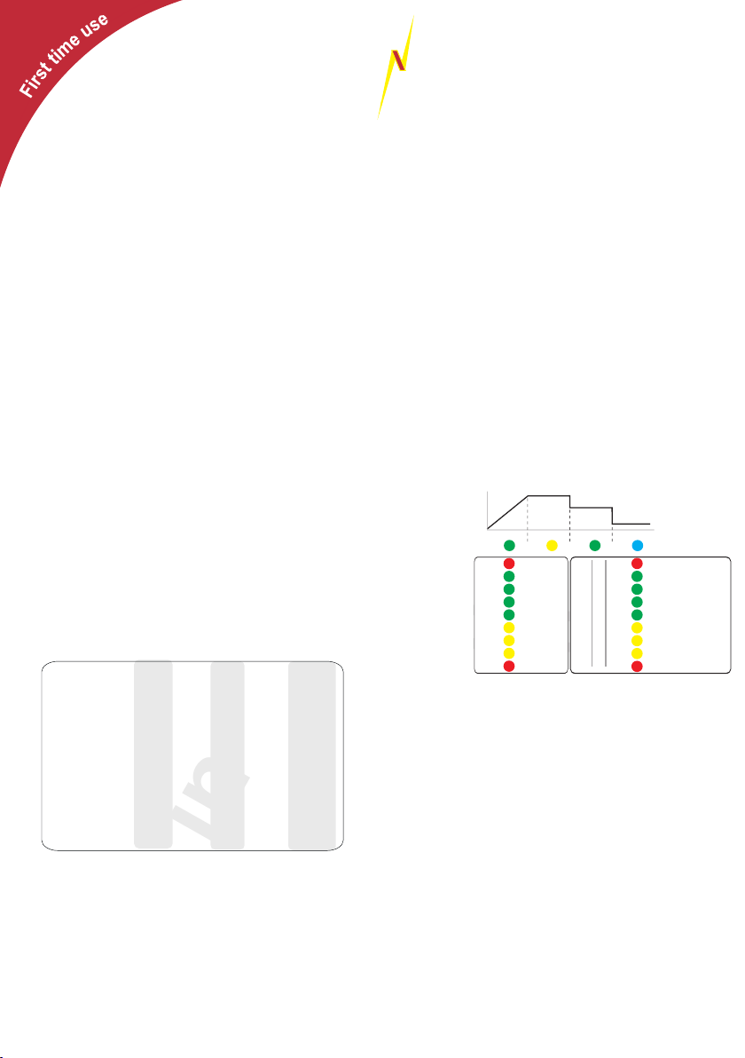
Normal Operation of front panel (with no alarms) after startup
Remote NOT connected:
Left bar = input voltage
Right bar = output voltage
Top line = charge state
Remote connected:
Left bar = no information
Right bar = status / faults of charger
Top line = charge state
At any point that the buttons are pressed, the button back light will flash.
There are various force select features available with this product which the average person
would never use but the features are there and available if required.
“Force” select options
Return to factory default: This stage is outlined first as if there is any problem with the set up of the
unit, then it may be helpful to start from the factory default. This will erase all previously entered settings
which is undoable. To return to defaults, Press and hold both buttons for 35 seconds. At this point both
sides of the LED rows will flash alternatively. To confirm this action, press and hold both buttons again for
2 seconds within 20 seconds of the LED’s flashing.
LED conformation: Restore to default will be confirmed by 5x flashing of the 3 green LEDs on the left
and 3 green LEDs on the right. The unit will now restart.
To check charger status ie to “force” convert the right side row off LEDs from an output volt meter to an
information panel .
By pressing the right button (SELECT) for about half a second, the left voltage row will turn off and the
status of charger will be displayed on right row for 10 seconds.
To return quickly to show the voltages again, press the left button (SETUP / ENTER).
“Force” float mode - Emergency procedure
Hold both setup and select buttons for 3 - 4 seconds
This charger is fully automatic and software controlled with algorithms to deal with most situations
however sometimes the user may feel it necessary to bypass the charge the algorithms and force it to
float mode.
To access this mode, press the left + right button for 3-4 seconds. This will lock the charger into float until
the unit has been reset by turning the engine and ignition off and all LEDs turn off. The charger will
resume normal operation on restarting.
LED conformation: The blue float LED on the battery graph will illuminate
“Force” unit off / on
Hold both setup and select buttons for 5 - 9 seconds
This will shut the unit down. The unit will remain off, even with normal engine cycling on and off (although
if the unit is disconnected from the input battery then it will resume normal operation on re-connection). To
turn the unit back on, hold the 2 buttons for 5-9 seconds.
LED conformation: the Left hand LEDS will go off and the status lights on the right will continue to work,
the float light will flash indicating the unit is off.
“Force” unit to ½ power (permanently)
Hold setup button only for 2-4 seconds
This will reduce the units power by about 50%. This function will help reduce noise in the long term. To
return to full power, press the setup button again for 2-4 seconds. To check if the unit is on power
reduction mode, press the select button for half a second. This will show the status of the charger, at this
point the power reduction LED will flash.
LED conformation: The power reduction led will operate for about 6 seconds to show you have engaged
this then the units LEDs will revert to voltage mode.
“Force” unit to ½ power and low speed fan for 8 hrs only (night mode)
Hold select button only for 2-4 seconds
This will reduce the units power by around 50% for about 8 hrs. This function will help reduce fan noise in
the short term, in the evening for example. The unit will revert back to full power after 8 hours
automatically. To check that night mode is engaged, press the select button for half a second where the
power reduction LED will flash. To exit this function press the setup and select buttons for 2-4 seconds.
LED conformation: The power reduction led will flash about 4 times to show you have engaged this. The
units LEDs will revert to voltage mode after.
In case of a fault:
The left voltage LED bar will switch off and right LED bar will no longer display voltage but will display the
charger status and fault.
If in event of fault - how to activate LED display volt meters
If there is a fault condition, knowing what voltages are can be useful for diagnostics. By pushing the left
hand button, the faults section will be disengaged and will return to display the voltage for 5 seconds to
assist with the diagnostics. You can repeat this as necesary.
BATTERY TYPE Selection and Custom set:
To select the battery type, the unit must be active, not in sleep mode or have any faults illuminated. The
unit will go into sleep mode in 1 minute after installation if the engine is not running or with no other
chargers active. All LEDs will go off apart from the button LED’s that will flicker occasionally to show unit
in sleep mode .
Battery type setup using pre set values (see pre set)
The unit must be in active mode (not sleep) for the battery type selection. There are two ways to activate
the unit from sleep.
A. The first way is to disconnect the battery input to the unit, and reconnect after 20 seconds. The unit will
then go through its start up sequence. When battery type displayed and button backlight on by pressing
both buttons you will enter into Battery type setup. You can also access the set up when the unit has
finished its start up sequence when the LEDs illuminated.
B. The second way is to bring the unit out of sleep mode by increasing the input voltage. You can
achieve this by starting the engine, or by using a mains charger. The LEDs should be active at this point.
Battery type selection (using the local LED panel)
1. Hold both buttons down for around 12-15 seconds. All of the LEDs on the left LED row will now flash.
2. To select the correct battery type, press the select button to go up the list, and the setup button to go
down. Move the LED that is lit next to the desired battery type.
3. To select your chosen battery type, press and hold both buttons for 2 seconds then release, or wait 30
seconds. This will be confirmed by the battery type you have chosen flashing for a short time and the unit
will then go through its start up sequence.
Of timer adjustment : default 2 mins (regen low voltage timer time)
The default auto ReGen time is 120 sec. = 2 min. If the input voltage falls below 13.3V ( x 2 for 24V) the
auto ReGen timer starts to count. If the voltage does not rise above 13.3V timer will not reset and the unit
will switch off, however as soon as the voltage rises above 13.3V the auto ReGen timer will automatically
reset to the set value (default = 120sec).
To deactivate the auto ReGen mode set the auto ReGen Time to 0 seconds!
To adjust timer
By pressing the Setup / Enter only button for more than 5 seconds you will enter the Auto Regen Time
Setup.
During the whole Auto ReGen Setup the “Absorption“ LED will flash.
1. Absorption LED flashing and actual saved auto ReGen time will be displayed on the right bar. Use the
0 to 840 scale. If the unit is out of the factory the 120 (default) should be displayed.
2 Press right button to increase or left button to decrease value.
3. To deactivate the auto regen function set timer value to 0
When happy with your choice either wait 30 seconds or press both buttons at the same time for 2
seconds.
4. Absorption LED, AGM2 and Auto Mode LEDs will flash 10 times to confirm value saving.
5. Unit will restart with new Auto ReGen time as default and will remain there until changed again.
Important: If you change the cutoff voltage remember that the auto Regen counter reset functions
must see 0.3V on top of the new cutoff voltage.
I.e. You set the new cut off voltage at 14.0V. To reset the Auto ReGen timer the voltage must rise
above 14.3V.
CUSTOM BATTERY TYPE SETTING (for expert use only - not required for general operation)
Before proceeding with this, please read and understand all instructions as it is quite complex and could
take more than one attempt. There are timed intervals of 30 seconds per setting so it is very important to
know exactly what you require before starting. The settings offered for adjustment in sequence:
Boost Charge Voltage > Condition Charge Voltage > Float Voltage > Time Factor > Minimum High
Voltage Charge Time > Maximum High Voltage Time.
Its best to write down the objective parameters you are going to set before entering this
procedure (space provided)
If any difficulty is experienced during this set up, leave the unit for 2/3 minutes. It will go through the
different setting automatically and then will restart where you can select the custom setting again.
Below is a description of all the settings that can be entered.
A) Boost / absorption voltage (high voltage charge).
B) Conditioning voltage (medium charge rate - Normally between boost and float voltage)
C) Float voltage (no longer charging, this will provide voltage at a reduced level to maintain the batteries
and provide power for any loads applied)
D) Time factor for absorption. (This will increase or decrease the algorithm setting. 16 being long - 0 being
short. This factor is determined by a multiplication of the time taken from start up until the boost voltage
reaches the predetermined setting multiplied by the factor selected. For example a gel may need a long
setting due to their slow charge features so you may choose a factor of 10. On the other hand AGM
batteries charges very quickly so hold the charge voltage down, there you may choose a lower factor of
say 4.)
If in any doubt, ask your battery retailer or use a preset.
E) Time for absorption
This is the maximum and minimum time you require on your battery charge. for example you may be on
AGM that may need a maximum of one hour, or GEL which could be 720 (12hrs minimum)
Use the space below to write down your target figures.
Boost (V) =
Conditioning (V) =
STERLI G
POWER
First turning the unit on
On first start up all LEDs will light up in a sequence.
The fan shall then start running for around 12
seconds. If, after this, 2 red LEDs flash for 8
seconds you may have a calibration issue and the
unit should be returned to Sterling. If 2 solid red
LEDs are on at the top or bottom then you either
have high or low input voltage (respectively) - check
your voltages.
Changing charging profile during startup
After the initial start up an LED on the left panel shall
light up for 10 seconds, this shall indicate the battery
type selected - default is sealed lead acid. This is
your window of opportunity to change the charging
profile. If you have missed the opportunity, you can
wait for the unit to go in to normal operation and
follow the instructions at the bottom of the page or
restart the device.
Hold down both buttons on the front panel (SELECT
and SETUP/ENTER) for 10 seconds. All LEDs on
the left column shall now flash. By using these two
buttons toggle through the various profiles (see
below). The right button is up the column and the left
button takes you down the column. The LED shall
light up demonstrating which profile you have
selected. When the LED has illuminated at your
desired profile simply hold both buttons for a couple
of seconds or simply just leave the charger alone for
30 seconds and it will change. The chosen profile
LED shall then flash. The unit shall then restart and
go through the starting cycle again.
**Charge Abs Float Min Boost Max Boost
Volts
14.00
14.10
14.40
14.40
14.60
14.80
15.10
15.50
14.40
Custom Charging Profile
Volts
13.70
13.40
13.60
13.80
13.70
13.30
13.60
--------
13.80
Mins
60
60
120
720
60
60
60
240
30
Mins
600
480
480
1440
480
480
360
240
30
Volts
13.85
13.75
14.15
14.00
14.10
14.00
14.30
--------
13.80
Options
1) Gel I
2) AGM I
3) Sealed
4) Gel II
5) AGM II
6) Open
7) Calcium
8) De-sulphation
9) *LiFePO4
10) Custom
Note - if you can only see LEDs on the right column
the chances are you are in an error mode. This
could be down to: Very low output voltages (<5V),
no output connection, reverse polarity or the device
is not detecting a valid operational mode as the
connector wire is either not connected or the
connection configuration is wrong. Please refer to
previous page.
Left and right meter readings.
During normal operation
Out of range voltage values
If voltage exceeds the meter’s range the upper right
LED shall flash. If the voltage falls short of the
meter’s range the lower LED shall flash. If two
neighbouring LEDs, on the voltmeter, are on
simultaneously then the real voltage is between
these two parameters. Example, if LEDs at 14.6V
and 14.2V were on then the approximate voltage
shall be ~14.4V.
Low or high output voltages
If the output voltage is below 5V (10V at 24V) or
reverse polarity then the low output voltage LED will
flash (number 23). Similarly, if the output voltage is
above 15.5V (31.0V at 24V) the high voltage LED
shall flash (number 16). To resurrect these
problems, bring the voltage above 6V on the output
and below 15.5V, correct the polarity and then
restart the device.
Changing charging profile during operation.
While the unit is running, simply hold down the
SETUP and SELECT buttons for 12-15 seconds
and let go. The LEDs on the left column shall light
up. The procedure hereafter is the same as above.
After unit has gone through its startup sequence the
LEDs displayed should be the input voltage on the
left column and the output voltage on the right
column. Also, the top left LED (number 12) should
be on solid which is the fast charge (bulk) LED.
15.4 V
15.0 V
14.6 V
14.2 V
13.8 V
13.4 V
13.0 V
12.6 V
12.2 V
Input voltage
(x2 for 24V)
Output voltage
(x2 for 24V)
FastCharge Absorb Cond. Float (s) / Standby (fl)
IUOU Battery charge
progress
Charge state ->
Remember it is the voltages which are more important
than our battery types. After installation test the voltage
from the unit is the desired voltage. Ensure you remove
at least 1 wire from the battery temperature sensor as
the product voltage may be higher ( if in cold climate )
or lower ( if in warn climate ) than the pre conceived
voltage. The voltage requirements of the battery
company will override our recommendations as it is them
who are supporting the battery warranty.
*Lithium profile has reverse polarity protection
disabled. **All voltages shall be 0.1V higher for the
first 3 minutes of the chargers operation.
Output Voltage
15.4V
15.0V
14.6V
14.2V
13.8V
13.4V
13.0V
12.6V
12.2V
16
14
12
10
8
6
4
2
0
840
720
600
480
360
240
120
30
0
High Volt in (fl) / out (S)
High temp trip (fl)
No Fault (S) / P.Pack (fl)
Auto (S) / 1/2 power (fl)
Batt. Sense on (S)
Volt drop sense (fl)
1/2 power (S) / night (fl)
Low Volt in (fl) / out (S)
High Batt. Temp (fl)
8


