BTI Elite PRO 6 Series User manual

Ph: 905.636.9865 Fax: 905.636.9879
1
January 01, 2020
Elite PRO 6-8-10
HIGH FREQUENCY ELECTRONIC
BATTERY CHARGER
OPERATING MANUAL
Attention: Carefully read this operating manual before connecting the
charger to AC supply and the battery pack.
GENERAL INFORMATION ABOUT THIS CHARGER
This device is an electronic battery charger with microprocessor control suitable for any lead
acid battery type when correctly set. Charging of lithium batteries is possible – see special
warnings for charging lithium batteries below.
Fully automatic charging with electronic setting; protected against overload, short-circuit and
reversed polarity.
WARNINGS
Never disconnect the battery while charging: this could cause sparks.
Never use the equipment in the rain, in areas used for washing or in damp areas.
Caution: the gases generated during charging are explosive. Do not smoke in the vicinity of
the batteries. When working with cables and electrical equipment, avoid open flames and
sparks.
Before starting to charge, make sure the voltage of the equipment suits the voltage of the
battery, that the charging current suits the capacity of the battery and that the selected
charging curve (for lead-acid wet batteries or VRLA - i.e. gel or agm - batteries) is correct for the
type of battery to be charged. In addition, make sure the rated input voltage of the charger suits
the available supply voltage and the system is grounded.
If necessary, replace the fuse with another of the same type and value as indicated on the
rating plate.
Use battery chargers only in well ventilated areas.
Pay attention to any remarks of the battery manufacturer.
To use the charger, you must abide by safety regulations contained in laws and any
regulations or other provisions stipulated by local authorities.
The user of the equipment is responsible for the installation site of the charger. They must
check if sensitive appliances are disturbed by the influence of the battery charger. They must
choose an installation site so that the operation of the charger does not affect the function of
electromagnetic devices and magnetic data carriers (e.g. pace makers, monitors, magnetic
disks and diskettes, magnetic tapes, magnetic cards, watches etc.), since a high direct
current may produce interfering magnetic fields.
Attention: Use protective glasses and gloves during battery maintenance. Battery acid
causes injuries. In case of contact with battery acid, wash the affected parts with fresh water
and consult a doctor if necessary.
This is an EMC compliant product in class A+B as defined by the CEI EN 61000-6-2, CEI EN
61000-6-3 and CEI EN 61000-6-4 regulations, in other words for use in both residential and in
industrial environments.

Ph: 905.636.9865 Fax: 905.636.9879
2
NOTE: The ability to select different levels for voltage and current for charging is in some
cases entrusted to the control and supervision of field technicians or the end user. Brierly
Technologies, Inc. is not liable for any consequences resulting from the selection of an
incorrect level of voltage or current or an incorrect battery type setting or programming. If in
any doubt, the field technician or end user should ask a qualified professional for clarification.
SPECIAL WARNINGS FOR CHARGING LITHIUM BATTERIES
In order to charger lithium batteries, a BMS (Battery Management System) must always be
used, comprising an active and passive safety system in compliance with any regulations in
force.
The function of the BMS acting directly on the battery charger operation during cell
balancing rules out, in any situation, that the battery charger can be held responsible should
any damage be caused to the battery or if there is any fire or explosion.
The battery charger tolerance values and thresholds, in terms of over-voltage and
overcharging, have no safety functions for the battery itself. The safety of the battery
depends solely on the BMS even when the battery charger is connected to the battery,
whether the battery is being charged or not.
Under no circumstances can Brierly Technologies, Inc. be held responsible for the
malfunctions of the batteries, fire or explosions as the safety of the battery is the task of the
BMS and not the battery charger.
INSTALLATION
Installation must be performed by a qualified electrician.
In some cases, the battery charger is not supplied with an AC power cord. It is the responsibility
of the electrician to use a properly rated supply cord for the installation.
OPERATION
Before operation, check that the battery charger programming/setting is correct for the
batteries, that the charging current suits the capacity of the batteries and that the selected
charging curve (for flooded lead-acid, valve regulated gel or agm, lithium) is correct for the
battery type to be charged.
Connect the battery pack, checking the polarity.
Plug the charger into the AC supply
Close the mains switch on the charger, thus starting the automatic charging cycle.
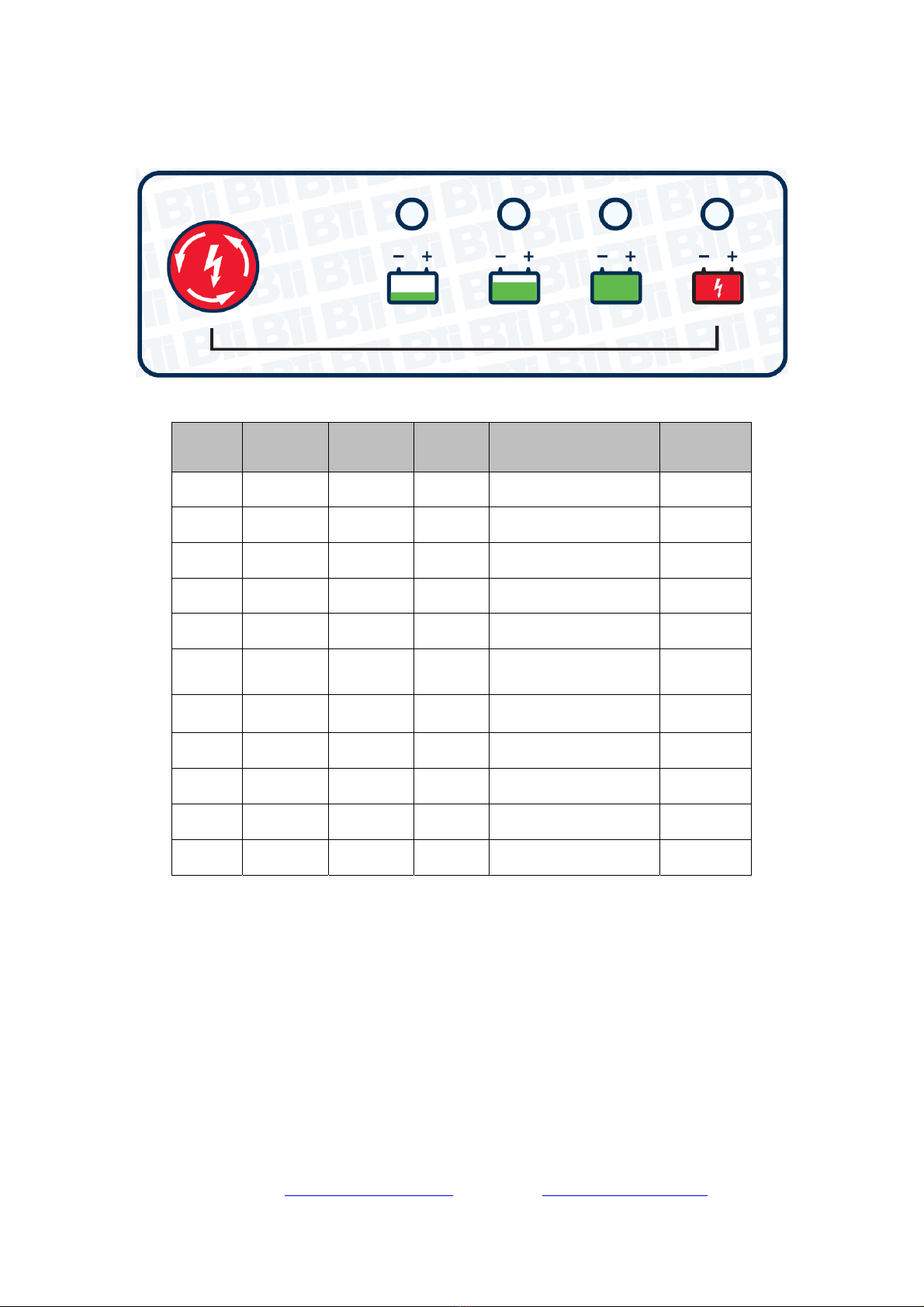
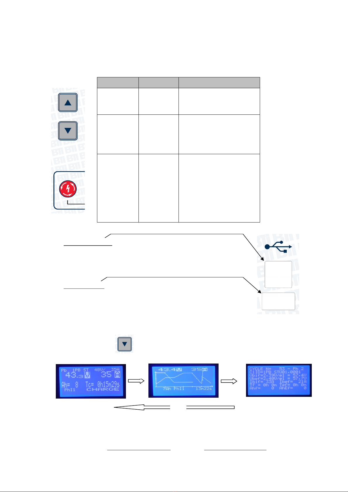
During the charging process it is possible to pause the cycle by pressing the red power
button on the display. To resume the charge cycle – press the button again.
To re-start the charge cycle, press and hold the red button for 3-4 seconds.
Once the charge cycle is completed and the charger needs to be disconnected from the battery
pack – first open the mains switch on the side of the charger. You can then disconnect the
DC-DC connector from your battery pack.
Store the DC cabling and connector is a safe manner.

Ph: 905.636.9865 Fax: 905.636.9879
3
VISUAL SIGNALS
This chart below explains the status of the charger via the 4 LEDs on the front display.
GREEN
LED
(DL4)
YELLOW
LED
(DL3)
GREEN
LED
(DL2)
RED
LED
(DL1)
DESCRIPTION DISPLAY
OFF OFF OFF OFF
Power supply from
batter
y
onl
y
OFF
OFF OFF OFF OFF
Power supply from AC
connected ON
ON OFF OFF OFF
Power supply from AC
and from batter
y
ON
BL BL BL BL
Charge is in start-up
mode. ON
BL OFF OFF OFF
Charging begins -
Phase 1 ON
BL ON OFF OFF
Charger in Phase 2 to 7
(# phases depends on
pro
g
rammin
g)
ON
ON ON ON OFF Equalize standby ON
BL BL ON OFF Equalization is ON ON
ON ON ON OFF
Equalization charge is
OFF
(
in standb
y)
ON
BL BL ON OFF
Maintenance / Float is
ON ON
ON ON ON OFF
Charging Process
Ended ON
Legend: OFF = the LED is OFF
ON = the LED is ON
BL = the LED is FLASHING (Blink time = 1 second)

Ph: 905.636.9865 Fax: 905.636.9879
4
KEYPAD FUNCTIONS
Technicians and users can interact with the battery charger using the UP and DOWN buttons and
the POWER button. Passwords are required for accessing and altering programming.
USB PORTS
The USB Service Port is to be used only for programming the charging
parameters and downloading of historical data and graphs.
You must disconnect the USB cable from the charger when in use to
prevent EMI noise from interfere with the charging process which may
unpredictable consequences for the charger and battery.
The USB Host Port is used for firmware updates and uploading charger
settings or profiles.
DISPLAY LCD
The battery charger display will show 3 menus to show charging details during the
charger process.
The DOWN ARROW button, will navigate between the menus consecutively.
The information provided by the monitor screens is shown below.
BUTTON FUNCTION DESCRIPTION
UP ARROW
Set-Up
Increase
Allows you to enter menus,
move around
Change or increase
parameters
DOWN
ARROW
Parameters
Decrease
Allows you to move between
monitor screens 1-2-3, view
various screen with charging
parameters
Change or decrease
parameters
POWER
On-Off
Select
Allows you to suspend or
restart the charge cycle or
select menu.
Also used to CONFIRM a
parameter when making
changes.
P2
P2
P2
MONITOR1
MONI
TOR2
MONIT
OR3

Ph: 905.636.9865 Fax: 905.636.9879
5
MONITOR1
ROW EXAMPLE DESCRIPTION
(1) Pb 1Pb ST 48V /35A Battery (Pb), Charging Curve # and Type (1Pb ST), Output of
Char
g
er
(
48V-35A
)
(
2
)
43.3 V 35A
A
ctive batter
y
volta
g
e
(
43.3V
)
and supplied output current
(
35A
)
.
(3) Ah= 8 Tc= 0h15m29s Ah provided to battery (8) and charging time in hours, minutes,
seconds
(
0h15m29s
)
(4) PhI1 CHARGE Active charging phase (PhI1)
Status of the batter
y
char
g
er.
(
CHARGE
)
(5) -- Messages Possible fault or status messages (none showing on sample screen)
MONITOR2
ROW EXAMPLE DESCRIPTION
(
1
)
43.4V 35
A
Instantaneous Batter
y
Volta
g
e
(
43.4V
)
and Output Current
(
35A
)
(2)
Active charging profile indicating :
- Phase completed (bold line)
- Active phase (flashing line)
- Phases pending (Thin line)
(3) 7Ah PhI1 13m22s Ah provided to battery in active cycle (7Ah)
Char
g
in
g
time in hours, min, sec.
(
13m22s
)
(
4
)
-- Messa
g
e Possible fault or status messa
g
es
(
none showin
g
on sample screen
)
MONITOR3
ROW EXAMPLE DESCRIPTION
(
1
)
CYCLE N= 53
–
Ph 2 Char
g
in
g
c
y
cle number
(
53
)
and active phase
(
2
)
(
2
)
C1ID=1PB ST_01.0001 Unique code number for the active char
g
in
g
curve
(3) Vbif=2.39V/el = 57.4V
Voltage of the battery in initial phase.
Shown as volts per element i.e. volts per cell (2.39) and as total
volta
g
e
(
57.4
)
(4) Vbef=2.40V/el = 57.7V
Voltage of the battery at the end of the active phase.
Shown as volts per element i.e. volts per cell (2.40) and as total
voltage (57.7)
(5) Ibif= 33A Ibef= 21A Current provided at the beginning of the phase (33A)
Current provided at ten end of the phase.
(
21
)
(6) Tf =0h0m Tef=0hm Elapsed time of the active phase (0h0m)
Total char
g
in
g
time at the end of the phase
(
0h0min
)
(7) Ahf= 0 AhEf = 0 Ah output in the active phase (0)
Total Ah
r
eturned to the batter
y
.
(
0
)
(
8
)
-- Messa
g
e Possible fault or status messa
g
es
(
none showin
g
on sample screen
)
TROUBLESHOOTING
If the charger display fails to light up - check the AC connection and power.
If the display light up but the charger does not start – check the last line of the Monitor1 display
for any possible error messages. This will show the class of the fault.
The Monitor 2 screen will show the detail of the fault – code and description.

Ph: 905.636.9865 Fax: 905.636.9879
6
If the charge is interrupted during the charging process the display will show as follows:
GREEN
LED
(
DL4
)
YELLOW
LED
(
DL3
)
GREEN
LED
(
DL2
)
RED
LED
(
DL1
)
DESCRIPTION DISPLAY
OFF OFF OFF OFF
Indicates a BLOCKING
fault has occurred OFF
OFF OFF OFF BL
Indicates a non-
blocking fault has
occurred
OFF
Pass this information and any error messages to a service technician for analysis.
RATING LABEL
The rating label on the side of the unit
provides the following details:
A – BTI part number
B – manufacturing part number
C – manufacturing model
D – input voltage and amp rating
E – output voltage and current
F – setting (battery type)
G – date of manufacture
H – serial number
I – warnings
L – product certification marking (cULus)
NOTE: The rating plate stipulates the initial setting of DC output voltage and current (E) plus
setting for battery type (F). The setting of your particular unit may be different if alered after
manufacture. Refer to the programming of the charger in the display screen as described above.
TECHNICAL DATA
Storage Temperature Range: - 20 to +50 degrees Celcius
Relative Humidity Range: 0 – 80% up to 50 decrees C
Operating Temperature Range: 0 to +40 degrees Celcius
INSTALLATION
The battery charger should be placed as far away from the batteries as the DC cable length
permits. This prevents gasses produced and/or emitted by the battery from corroding or otherwise
damaging the charger.
Do not install the battery charger in a closed space or in such a way as to prevent ventilation.
See illustration below for recommended floor, wall and ceiling clearances.
Do not use outdoors. Do not expose to rain, water splashes or steam. Do not install near heat
sources or in areas with high concentrations of dust. Do not install near any sources of
flammable material such as gases or fuels. Do not place or fit the charger on or near surfaces
manufactured out of combustible materials such as wood.

Ph: 905.636.9865 Fax: 905.636.9879
7
AC POWER CONNECTION
This charger is cULus Listed. Units may be supplied without an AC cord or AC plug. Supply of
an appropriate AC cable and plug for connection to AC must to be performed only by qualified
personnel.
It is essential to connect the charger to a mains supply of standards corresponding to the power
of the battery charger installed.
THREE PHASE 200/208/220/400/480 VAC
Make sure to earth the charger properly where relevant using minimum AWG10 wire.
Note the internal label showing the connection order of the power cord conductors:
(EMPTY, LINE1, LINE2, LINE3, GROUND)
REPAIRS
Repairs must only be carried out by qualified personel.
Use only original type parts for repairs.
ELECTROMAGNETIC COMPATIBILITY
This battery charger complies with the following standards:
EN 55014-1 (Emission)
EN 55014-2+A1+A2 Immunity – Category II)
EN 61000-3-2 (Harmonic Current Emission)
EN 6100-3-3 (Voltage Fluctuation and Flicker)
WARNING!!!
Connect the mains conductors in the order
shown below:
USE WIRES SUITABLE FOR AT
LEAST 75 DEG C
LI L2 L3 PE

Ph: 905.636.9865 Fax: 905.636.9879
8
SAFETY AND ELECTRICAL APPROVALS
EN 60335-2-29: “SAFETY OF HOUSEHOLD AND SIMILAR ELECTRICAL
APPLIANCE – PART 2; PARTICLAR REQUIREMENTS FOR BATTERY CHARGERS”.
EN 62233: MEASURMENT METHODS FOR ELECTROMEGNETIC FIELDS OF
HOUSEHOLD APPLIANCES AND SIMILAR APPARATUS WITH REGARD TO HUMAN
EXPOSURE”.
15JC
E249016
This manual suits for next models
2
Table of contents
Other BTI Batteries Charger manuals