Stern TUBULAR Product manual

1
TOUCH FREE WALL MOUNTED SOAP DISPENSERS
INSTALLATION AND MAINTENANCE GUIDE
TUBULAR
QUADRAT

1
INDEX TECHNICAL DATA
Capacity Liter \ . oz., or 6 Liters / . Gallons
Power Supply Battery models: Battery Box for xD Alkaline batteries
Mains models: V transformer
Soap viscosity cPs
Standard discharge .cc (customizable by optional remote control)
Sensor range mm +/- mm /..” (customizable by optional remote control)
Preset sensor range mm +/- mm /.” +/- .
TUBULAR SOAP DISPENSER B
TUBULAR SOAP DISPENSER E
QUADRAT SOAP DISPENSER B
QUADRAT SOAP DISPENSER E
QUADRAT 2030 SD 1.6 E
QUADRAT SD 1.6 E
TUBULAR 2030 SD 1.6 E
QUADRAT SOAP DISPENSER 2030 B
QUADRAT SOAP DISPENSER 2030 E
TUBULAR SD 1.6 E
TUBULAR SOAP DISPENSER 2030 B
TUBULAR SOAP DISPENSER 2030 E
TECHNICAL DATA
PRE-INSTALLATION INFO
PACK CONTENTS
INSTALLATION
FILLING THE SOAP TANK
SETTINGS ADJUSTMENT WITH A REMOTE CONTROL
BATTERY REPLACEMENT
SPARE PARTS LIST
MAINTENANCE
LIMITED WARRANTY
TROUBLESHOOTING

2 3
PRE-INSTALLATION INFO PACk CONTENTS
TUBULAR/QUADRAT SOAP DISPENSER
Familiarize yourself with the part names and ensure that all the parts are included in
your package.
Check contents
Separate all parts from the packaging and check each part with the “Pack contents”
section.
Make sure all parts are accounted for before discarding any packaging material.
If any parts are missing, do not attempt to install your touch free soap dispenser until you
obtain the missing parts.
Warnings
Do not install the system facing a mirror or any other electronic system operated by an
infra-red sensor.
To prevent reflection problems, it is recommended to keep a minimum distance of
mm between the soap dispenser and any other objects.
Liquid soap dispensers, with proper care, will provide long term trouble free service.
Quality liquid soap of recommended viscosity and pH levels are the main factors for
smooth operation of your dispenser. If needed, use a viscometer to verify the viscosity
of your soap to ensure maximum benet. The recommended range for liquid soap
viscosity is cPs. Thicker liquid soap flows slower and inhibits the pump valve,
causing strain and damage.
Liquid soap dispensers are suitable for use with any generic liquid soap of the correct
viscosity and pH. The pH level of all soap used in our liquid soap dispensers should be
between . to .. Lower levels will cause corrosion to the metal dispenser and even the
rubber and plastic components. Higher pH levels will cause swelling to rubber parts and
degradation of plastic components over time.
IMPORTANT: Keep in mind that when using the faucet installed next to the soap
dispenser, the user hands should not interfere with the soap dispenser sensor
detection area.
1 X SOAP TANk WITH BOTTLE SUPPORT
AND PUMP ASSEMBLy
1 X BATTERy BOX FOR 6XD ALkALINE
BATTERIES \ 12v TRANSFORMER
1 X BODy ASSEMBLy FOR TUBULAR SOAP
DISPENSER B / E
1 X BODy ASSEMBLy FOR QUADRAT SOAP
DISPENSER B / E
B vERSIONS E vERSIONS
X M X
SET SCREW
X M X
SET SCREW
X QUICK
CONNECTION
FITTING
X SCREW
.X /”

4 5
PACk CONTENTS
STEP 1 – PREPARATION FOR INSTALLATION
Drill a hole ( to mm) at the desired
location for the soap dispenser spout
installation.
Drill a small hole ( to mm) just above
the previous one for the anti-rotation pin,
according to the diagram.
Remove the hexagonal nut and the disk from
the base of the soap dispenser spout.
STEP 2 – INSTALLINg THE SOAP DISPENSER
Insert the Soap dispenser base and
the anti-rotation pin into the holes
drilled.
Fix the base behind the wall with the
hexagonal nut and the disk.
Fix the bottle with bottle support to
the desired location.
INSTALLATION
Recommended hole size
16mm
0.63”
23-24mm
0.90-0.94”
SOAP DISPENSER BASE
DISK
ANTI-ROTATION PIN
HEXAGONAL NUT
1 X SOAP TANk WITH BOTTLE SUPPORT
AND PUMP ASSEMBLy
1 X BATTERy BOX FOR 6XD ALkALINE
BATTERIES \ 12v TRANSFORMER
B vERSIONS E vERSIONS
1 X ELBOW AND
CORRUgATED TUBE 1 X WALL ROSETTE
1 X BODy ASSEMBLy FOR TUBULAR SOAP
DISPENSER B / E
1 X BODy ASSEMBLy FOR QUADRAT SOAP
DISPENSER B / E
X TEMPORARY
BASE COVER
X M X
SET SCREW
X M X
SET SCREW
X QUICK
CONNECTION
FITTING
X SCREW
.X /”
TUBULAR/QUADRAT SOAP DISPENSER TUBULAR/QUADRAT SOAP DISPENSER

6 7
INSTALLATION
Connect the soap tube that is
coming out of the soap dispenser
body to the quick connector at the
top of the soap dispenser pump
assembly by snapping it in.
STEP 3 – CONNECTINg THE POWER SOURCE
Remove the protective sticker
covering the sensor. Keep away from
the sensor range and check that no
objects are in front of the sensor.
Connect the soap pump
connector to the matching
connector from the sensor.
Please note that since the
connector is waterproof, some
friction might apply.
O-RING VISIBLE –
NOT CONNECTED PROPERLY
ONLY THE GROOVES ARE VISIBLE –
CONNECTED PROPERLY
INSTALLATION
IMPORTANT: the contacts connector should be connected properly so that the white
o-ring is not visible and a clicking sound is heard.
PAY ATTENTION: If the contacts connectors will not be connected properly, the pump
will work continuously.
a
For battery versions: install the
battery box on the wall underneath
the sink and connect the battery
connector
FROM THE SOAP
DISPENSER
TO THE BATTERY BOX
b
For transformer versions: plug the
transformer into the electricity
socket and connect the transformer
connector FROM THE TRANSFORMER TO THE SOAP DISPENSER
Wait about 10 seconds before
you put your hands within the
sensor range to avoid entering the
adjustment mode.
SECONDS
ABOUT
TUBULAR/QUADRAT SOAP DISPENSERTUBULAR/QUADRAT SOAP DISPENSER

8 9
INSTALLATION
Assemble the corrugated tube to the
soap dispenser base and make sure
it will stay outside of the wall when
tiling.
Once the works on electricity,
plumbing and tiles have been
nished, insert the wall rosette
through the soap dispenser
base, and cut the temporary soap
dispenser base cover.
Fix the soap dispenser spout by
inserting the nipple into the soap
dispenser base and tighten the
screw.
Pull the four way connector and the
power supply connector out of the
soap dispenser base, and lead it
through the corrugated tube.
INSTALLATION
STEP 1 – INSTALLINg THE MF SOAP DISPENSER
Cut an adequate opening in the wall for
the dimensions of the soap dispenser
base (where you want to install the
spout) and the corrugated tube.
Disconnect the soap dispenser body with
the rosette from the base by unscrewing
the set screw.
SET SCREW
Mount the soap dispenser base into the
opening in the wall and secure it using
the two anchors provided in the package.
Important: The soap dispenser base
should be installed so that the outside
surface of the nished wall falls between
the minimum and maximum lines marked
at the base.
Assemble the temporary protective soap
dispenser base cover.
Assemble the corrugated tube to the
soap dispenser base and make sure it
stays outside the wall when you do the
tiling.
MIN MAX
TUBULAR/QUADRAT SOAP DISPENSER TUBULAR/QUADRAT SOAP DISPENSER

10 11
INSTALLATION
STEP 3 – CONNECTINg THE POWER SOURCE
Remove the protective sticker
covering the sensor. Keep away from
the sensor range and check that no
objects are in front of the sensor.
Connect the soap pump
connector to the matching
connector from the sensor.
Please note that since the
connector is waterproof, some
friction might apply.
O-RING VISIBLE –
NOT CONNECTED PROPERLY
ONLY THE GROOVES ARE VISIBLE –
CONNECTED PROPERLY
IMPORTANT: the contacts connector should be connected properly so that the white
o-ring is not visible and a clicking sound is heard.
PAY ATTENTION: If the contacts connectors will not be connected properly, the pump
will work continuously.
2a
For battery versions: install the
battery box on the wall underneath
the sink and connect the battery
connector
FROM THE SOAP
DISPENSER
TO THE BATTERY BOX
2b
For transformer versions: plug the
transformer into the electricity socket
and connect the transformer connector
FROM THE TRANSFORMER TO THE SOAP DISPENSER
Wait about seconds before
you put your hands within the
sensor range to avoid entering the
adjustment mode. 10
SECONDS
ABOUT
TUBULAR/QUADRAT SOAP DISPENSER
FILLINg THE SOAP TANk
Unscrew the soap tank from the pump assembly and
pull it out from the bottle support.
Fill in the liquid soap up to the top line.
Insert the bottle back into the bottle support.
Screw the soap tank back into the pump assembly.
Make sure the tank is rmly secured into place.
Press the rell button located at the back of the
pump assembly until soap starts coming out of the
soap dispenser spout. This operation can also be
done using the soap dispenser remote control Rell
function.
NOTE: Once the soap in the soap tank has reached
the bottom line the soap tank should be relled. To
rell the soap tank please refer to steps .
If your model is an MF model, please refer to the Multifeed installation guide.

12 13
SETTINgS ADJUSTMENT WITH A REMOTE CONTROL
If available, the soap dispenser remote control can adjust the dispenser’s settings. To
use the remote control hold it in front of the sensor at a distance of 10-15cm (”).
Attention: The remote control will not operate out of the recommended range (too close
or too far).
The remote control can be used to adjust the following functions:
1-SOAP QUANTITy
The drop keys allow the user to choose the desired soap quantity.
. to . cc *
. to . cc
. to . cc
. to .cc
Indication: continuous blinking of the light in the sensor eye.
3
4
2-ADJ
This function resets the sensor back to factory
settings.
Indication: blinks of the light in the sensor eye.
3-TEMPORARy OFF FUNCTION
This function temporary disables the
dispenser. Use this function to preform
maintenance in front of the sensor without
activating the system (for example: cleaning).
The soap dispenser will shut o for one minute
aer this button is pressed once.
To return to normal operation before the
minute is over, press the On/O button again.
Indication: OFF – fast blinks, ON – fast blinks
4-FILL THE SOAP TANk
Once the soap tank has been lled \ relled,
press the FILL button. The pump will run for one
minute, priming the piping with soap. Once soap
begins dispensing from the spout, priming is
complete. press the FILL button again to stop the
priming before the minute is over.
Indication: continuous solid light in the sensor
eye.
BATTERy REPLACEMENT
Battery models only
When the battery weakens, the red indicator light will blink at a constant rate when the
user’s hands are within the sensor range. The battery must be replaced within two weeks.
To replace the battery in battery models:
. Carefully open the battery box, use a . mm Allen key
. Remove the old batteries
. Replace the used batteries with new D batteries
. Close the box.
NOTE: Do not mix used batteries with new ones.
Important: Spent batteries should not be disposed of with
normal household waste. Contact your local authority
for information on waste disposal and recycling.

14 15
SPARE PARTS LIST
PACK SENSOR KIT
SOAP DISPENSER PUMP
PACK SOAP BOTTLE L
PACK SOAP BOTTLE L SUPPORT KIT
BATTERY BOX FOR XD BATTERIES
V TRANSFORMER EU
V TRANSFORMER UK
V TRANSFORMER US
V TRANSFORMER AU
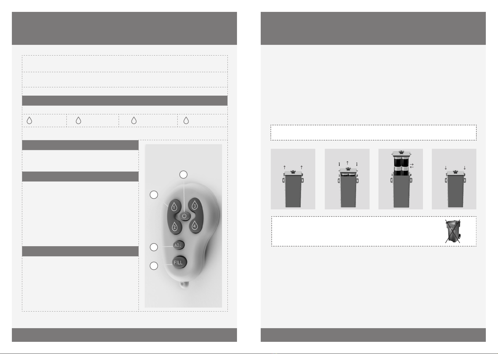
REMOTE CONTROL FOR SOAP DISPENSER (OPTIONAL)
SOAP & WATER REMOTE CONTROL (OPTIONAL) 07100014
MAINTENANCE
Care and cleaning of chrome and special nishes
DO NOT use steel wool or cleansing agents containing alcohol, acid, abrasives, or the like.
Use of any prohibited cleaning or maintenance products or substances could damage the
surface of the soap dispenser. For surface cleaning use ONLY soap and water, then wipe
dry with a clean cloth or towel. When cleaning bathroom tiles, the soap dispenser should
be protected from any splattering of harsh cleansers.
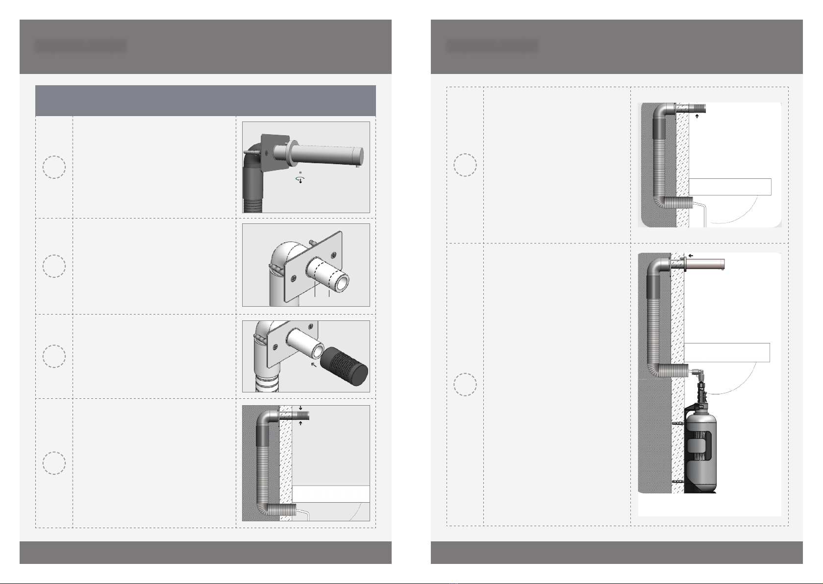
Disassemble of the soap pipe from the pump
The soap pipe can be disconnected from the soap pump by a simple slide & pull action.
The sliding ring of the quick connection xation nipple on the pump should be pulled
down. It releases the open end of the soap pipe which can then be easily pulled out.
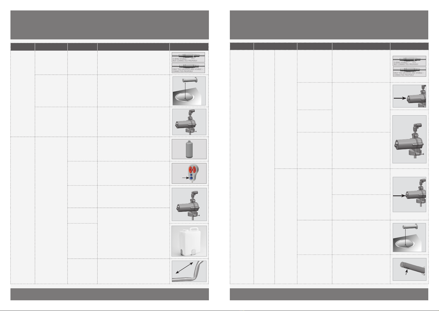
Clean the soap tank
Clean out the tank prior to rell by flushing warm water through the hoses and pump until
clean water is released from the spout. TIP: Keeping a spare tank will enable this process
to be completed in a speedy and hygienic manner with minimal downtime.
LIMITED WARRANTy
The manufacturer warrants that its electronic products will be free of defects in
material and workmanship during normal use for two years from the date the product is
purchased.
If a defect is found in normal use, the manufacturer will, at its discretion, repair, provide
a replacement part or product, or make appropriate adjustments. Damage caused by
accident, misuse, or abuse is not covered by this warranty. Improper care and cleaning
will void the warranty. Proof of purchase (original sales receipt) must be provided to the
manufacturer with all warranty claims.
The manufacturer is not responsible for labor charges, installation, or other incidental or
consequential costs other than those noted above. In no event shall the liability of the
manufacturer exceed the purchase price of the product.
If you believe that you have a warranty claim, contact your Distributor, Dealer or Plumbing
Contractor. Please be sure to provide all pertinent information regarding your claim,
including a complete description of the problem, the product, model number, the date
the product was purchased, from whom the product was purchased and the installation
date. Also include your original invoice.
THE MANUFACTURER AND/OR SELLER DISCLAIM ANY LIABILITY FOR SPECIAL, INCIDENTAL
OR CONSEQUENTIAL DAMAGES. This warranty excludes product damage due to
installation error, incorrect maintenance, wear and tear, battery, product abuse, or
product misuse, whether performed by a contractor, service company, or the consumer.
This warranty does not cover product damage caused by the following:
- Incorrect installation.
- inversions of supply pipes.
- Pressures or temperatures exceeding recommended limits.
- Improper manipulation, tampering, bad or lapsed maintenance.
- Foreign bodies, dirt or scale introduced by the water supply or soap tank.
- Use of the soap outside of viscosity specications.
- Alteration of the original soap/foam dispenser components (including pipes).

16 17
TROUBLESHOOTINg TROUBLESHOOTINg
IllustrationSolutionCauseInvestigationIndication
O-RING VISIBLE –
NOT CONNECTED PROPERLY
ONLY THE GROOVES ARE VISIBLE –
CONNECTED PROPERLY
The connector should be inserted fully until
white o-ring is not visible. Remove the o-ring if
necessary
AUX connector not
fully inserted
Continuous
discharge from the
nozzle
False
activation:
Soap
dispensing
Min mm.
Bottom of the washbasin
Eliminate any cause of reflection and if
necessary use appropriate remote control to
shorten detection range.
Reflection issue
from basin or
other object
Random discharge
from the nozzle
Replace the Pump. Rinse warm water through
the pipe and the body of the soap dispenser all
the way to the nozzle.
Damaged pump
due to high
viscosity or debris
in pipes
Soap discharging
from pump housing.
Fill with soap with correct viscosity (
cPs) and prime pipes using the ll button on
remote control.
Soap tank is
empty
Pump is making
sounds when sensor
is activated
Soap not
dispensing
Press
FILL
Button
Prime the soap dispenser by pressing the ll
button on the remote or by pressing the rell
button located at the bottom of the pump, until
soap exits the nozzle.
Soap dispenser
has not been
primed
Replace the PumpDamaged pump
(discharge from
housing)
Run warm water through pipe, pump, and body
all the way to the nozzle. Replace with soap of
correct viscosity.
NOTE: Using the soap dispenser with high
viscosity soap may cause permanent damage to
the pump and shorten the lifecycle.
Debris or dried
soap in the pipe
or tank
Soap Viscosity
cPs)
High viscosity
soap
(> cPs)
Unbend or straighten pipes.Bent pipes
IllustrationSolutionCauseInvestigationIndication
O-RING VISIBLE –
NOT CONNECTED PROPERLY
ONLY THE GROOVES ARE VISIBLE –
CONNECTED PROPERLY
The connector should be inserted fully
until the white o-ring is not visible.
Remove the o-ring if necessary
AUX connector not
fully inserted
Sensor is
blinking
when hand
is placed in
front
Pump is
not making
sound when
the sensor is
activated
Soap not
dispensing
Press
Replace the Pump. Rinse warm water
through the pipe and the body of the
soap dispenser all the way to the
nozzle.
Rell button on pump
does not activate the
pump.
Damaged pump
(discharge from
housing).
Run warm water through pipe, pump,
and body all the way to the nozzle.
Replace with soap of correct viscosity.
NOTE: Using the soap dispenser
with high viscosity soap may cause
permanent damage to the pump and
shorten the lifecycle.
Debris or dried soap in
the tank or tubing
Rell
button
Transformer: Check operation with
functioning transformer. Where
necessary replace with appropriate
transformer. For part numbers see
spare parts list.
Rell button on pump
does not activate the
pump.
Sensor is
not blinking
when hand
is placed in
front
Battery: Check operation with
functioning battery pack. Where
necessary, replace batteries or replace
the battery pack: Battery pack (without
batteries)
Min mm.
Bottom of the washbasin
Eliminate any cause of reflection and
use appropriate remote control to
shorten detection range.
Reflection issue from
basin or other object
Replace
sensor
If the above two solutions have not
resolved this issue replace with
appropriate sensor. For part numbers
see spare parts list.
Damaged sensor

18
. C
This manual suits for next models
21
Table of contents
Other Stern Dispenser manuals
Popular Dispenser manuals by other brands

PRESERVE
PRESERVE Cutlery Dispenser manual

HERWE
HERWE VIVA manual

DEMA
DEMA Laundry Master 830 installation instructions

START International
START International Label LD5000 quick start guide

Cornelius
Cornelius Millennium II 6000 installation manual

Scottoiler
Scottoiler LOUIS SPECIAL EDITION Instructions for installation and use

NESTLE
NESTLE Vitality Express Extended Shutdown and Startup Procedure

U-Line
U-Line TORK H-5808 quick start guide

BOWMAN
BOWMAN Hand Sanitizer Floor Stand Plus quick start guide

ophardt
ophardt SanTRAL HSU Instructions for use

Halsey Taylor
Halsey Taylor GBVAHC*U owner's manual

Coca-Cola
Coca-Cola Freestyle 7000 user guide