STI CMCP810 Series User manual

CMCP810SERIESRUNOUTKIT
WITHSENSORINTERFACEMODULE
INSTRUCTIONMANUAL
STIVIBRATIONMONITORINGINC
WWW.STIWEB.COM
REVA.1

CMCP810‐SIMManual
Rev.A.2
www.stiweb.comSTIVibrationMonitoringInc.
LeagueCity,TexasUSA
PublishedJuly2013
Page:1
AbouttheRunoutKit
TheCMCP810SeriesElectricalRunoutKitusesindustrystandardsensorstodetectandlocateareasofhighelectrical
runout.ElectricalrunoutmustbeminimizedtoallowProximityprobestoworkproperlywhilethemachineisinoperation.
Thekitcombinesthetypicalindustrialsensorsnormallyusedforpermanentvibrationdetectioninordertoallowforin
shopdetectionofelectricalrunoutusingthesuppliedoscilloscope.Electricalrunoutcanbedetectedandrecordedusing
thewaveformfunctionandthenprocessedforreportingusingtheoptionalFlukeViewsoftwareforPC’soraPCbased
Oscilloscope.TheCMCP810RunoutKitissuppliedwiththefollowingparts;
Fluke192SeriesScopemeterorPicoscopePCBasedOscilloscope
OscilloscopeCharger
CMCP810‐SIMSensorInterfaceModule(BatteryPowered)
CMCP810‐SIMCharger
200mV/milProximityProbeSystem(ProbeandDriver)
OpticalPhaseReferenceSensor
RollReflectiveTape
TwoMagneticFlexibleArmSensorHolders
TwoBNCtoBNCCables
BananatoBNCAdapter
ClipboardwithManualsandOptionalSoftware
TheBasicsofanEddyCurrentProbeSignal
AnEddyCurrentProbeisanon‐contactsensorcapableofthemeasuringthepositionofaferrousmaterialwithhigh
resolution.Theoutputoftheprobecanbeviewedasawaveformshowingthemotiontowardsandawayfromtheprobe.
Inordertodisplayapositiveandnegativegoingsignalinelectronicsanoffsetvoltagemustbeprovidedtoallowthevoltage
signaltoswingupanddown.TodothistheeddyprobedrivercreatesaDCoffsetvoltagefortheACvoltagesignaltoride
on.TheDCvoltageisreferredtoasthe“gap”voltageandistypicallysetto‐12VDC.Sincemostmodernoscilloscopesonly
allowforuptoa5VDCoffsetabuckingcircuitmustbeusedtomovethe‐12VDCoffsettowithintheoscilloscopes
measurementrange.
AbouttheSensorInterfaceModule(CMCP810‐SIM)
TheCMCP810SIMSensorInterfaceModuleprovidesasingleaccesspointforthesensorsandoscilloscope,eliminatingthe
needofdualpowersuppliesandamixofwiringinbetween.Aninternallithium‐ionbatteryprovides‐24VDCforthe
ProximityProbeand+15VDCforthePhasesensor.Thebatterycanberechargedusingthechargerprovidedwiththe
CMCP810SIMmodule.Sparebatteriesmayalsobepurchased.ThemainpurposeoftheSensorInterfaceModuleisthe
buckingamplifiercapabilities.TheCMCP810SIMcanremovetheentireDCoffsetsothatonlytheACsignalisviewableon
theoscilloscope.
CMCP810‐SIMFrontPanelConnections
ThefrontoftheCMCP810SIMmodulefeaturesaOn/OffswitchwithanLEDOnindicator,VoltageAdjustknobandtwoBNC
connectorsforthesignaloutputs.Oncethesensorsandoscilloscopeareconnected,theVoltageAdjustknobcanbesetso
thattheProximityProbessignaliswithintheoscilloscopesviewingrange.

CMCP810‐SIMManual
Rev.A.2
www.stiweb.comSTIVibrationMonitoringInc.
LeagueCity,TexasUSA
PublishedJuly2013
Page:2
CMCP810‐SIMRearPanelConnections
ThebacksideoftheCMCP810SIMmodulefeaturesthePhaseandEddyProbesensorinputsandbatterychargersocket.
A3‐wireadapterisprovidedtoallowtheCMCP810SIMtoconnecttotheEddyProbeDriver’swireterminals.Seewiring
detailsonthe3‐wireadapter(Signal,‐24VDCandGND).
AbouttheSensors
ProximityProbe:
ThesuppliedProximityProbeisthesametypeofsensor
normallypermanentlyinstalledtomeasurevibration.
Thismodelsensorprovidesa200mVoutputpermil
(0.001”)ofelectricalrunoutona4140seriesshaft.An
ProximityProbeismadeupofthreespecificallytuned
components,theprobe,extensioncableanddriver,all
threemustbeconnectedtogetherinorderforitto
operate;unlikemanyinstrumentsthissensoris‐24VDC
poweredandpoweredissuppliedbytheCMCP810‐SIM
SensorInterfaceModule.Tolearnmoreabouthow
EddyProbesoperateseeourapplicationnoteonRadial
VibrationintheKnowledgeBasesectiononourwebsite.

CMCP810‐SIMManual
Rev.A.2
www.stiweb.comSTIVibrationMonitoringInc.
LeagueCity,TexasUSA
PublishedJuly2013
Page:3
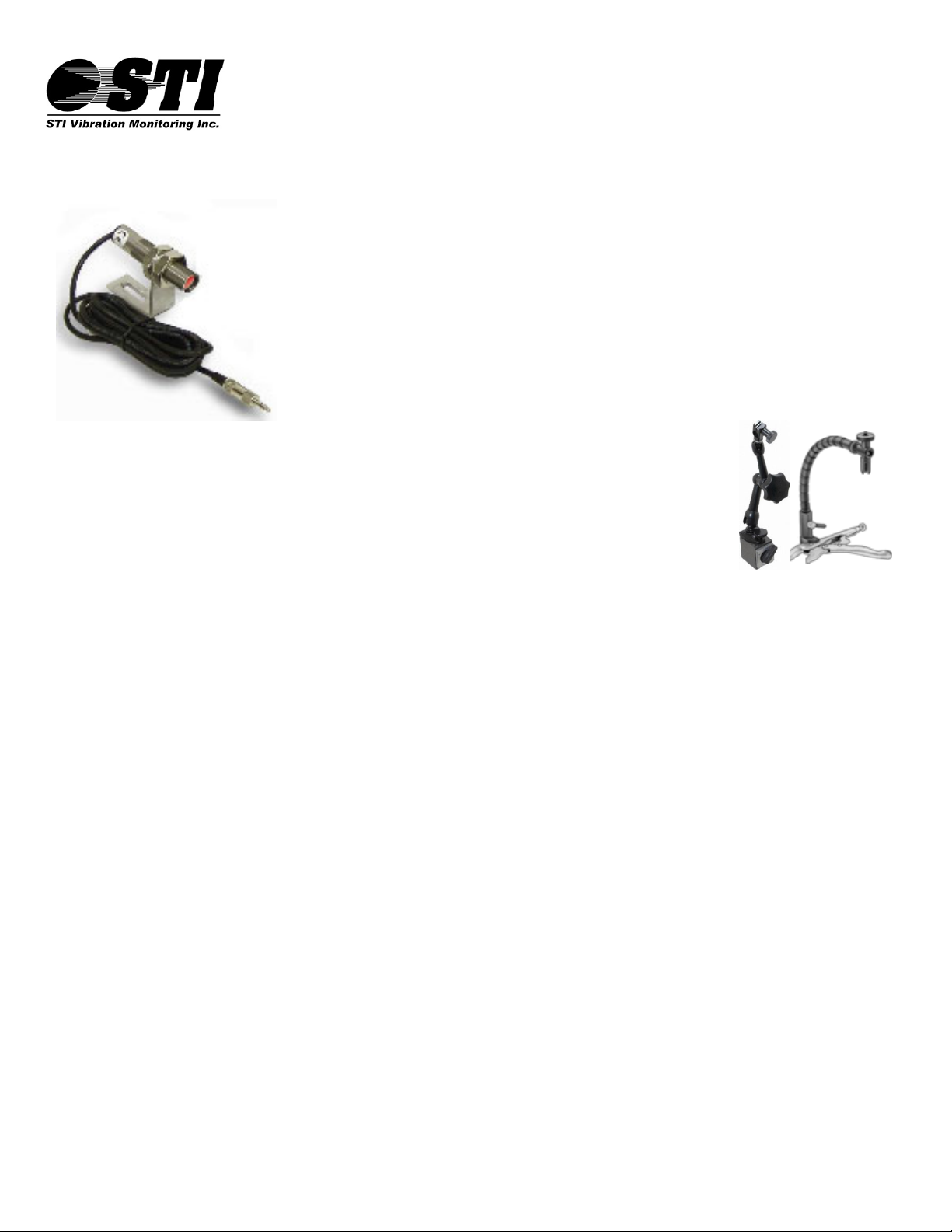
AbouttheOpticalSensor
OpticalSensor:
TheopticalsensorprovidedwiththeCMCP810RunoutKitprovidesaphase(location)reference
totheelectricalrunout.ThesensorispoweredbytheCMCP810‐SIMSensorInterfaceModule.
Whenthesensordetectsareflectivesurface,theoutputwillspiketo5VDC.Arollofreflective
tapeisprovidedwiththekit.ThepowerunitfortheopticalsensorcanoperateonACpoweror
ontheinternalbatteries.Theoscilloscopeshouldbesetupsothatatleastonerevolutionofthe
shaftisdisplayedontheoscilloscopescreenwhiletheshaftisturning.Thiswillallowthe
operatortoseetheareaofthehighelectricalrunout.
SensorMountingOptions:
TheCMCP810Kitcomeswith2sensormountingoptions,theadjustablemagneticarmholders
andcustomvicegrips.Theholderscanbeusedwitheithersensorandinanyorientationthat
allowsthesensorssositsecurelyabovethetargetpositions.Itisimportantthattheproximity
probedoesnotmoveduringthemeasurementprocess.
SensorPlacement
ProximityProbe(Runout):
TheProximityProbeshouldbeinstalledinoneofthesuppliedholdersandpositionedabovetheburnishedareaoftheshaft
asspecifiedintheshopdrawings.Theproberequiresagapbetweentheshaftandtheprobetipinorderforittooperate
correctly.ThegapcanbesetbymeasuringtheDCvoltageoutputfromthedriver,positionthesensoruntiltheoutputfrom
thedriverreadsapproximately‐12VDCusingthevoltmeterfunctionontheoscilloscope,thisgapvoltagecorrespondsto
about60milson4140seriessteel.TomeasurethegapvoltagewiththeScopeMetersimplydisconnecttheChannelABNC
Cable,attachtheBananatoBNCAdapterandplugintothevoltageinputconnectors.Takenoteofthepolaritywhenusing
theadapter,thecommonlughasaflagonthepostshowing“GND”.AftergappingtheprobebesuretomovetheBNCcable
backtotheChannelAinput.DuringrunoutmeasurementstheProximityProbeshouldbesettoChannel1,alsoknownas
ChannelA,whichisdisplayedonTraceA.
OpticalSensor(Phase):
TheopticalsensorshouldbeinstalledinoneofthesuppliedholdersandpositionedneartheProximityProbe.A1”pieceof
thesuppliedreflectivetapeneedstobeplacedontheshaftbelowthesensor.Thegapbetweentheopticalsensorandthe
reflectivetapecanbeupto6”.Toverifythatthesensorissensingthereflectivetaperotatetheshaftandvisuallyinspect
thatthegreenlightonthebackoftheopticalsensorflickersonceperrevolution.Duringtherunoutmeasurementthe
opticalsensorshouldbesettoChannel2,alsoknownasChannelB,whichisdisplayedonTraceB.
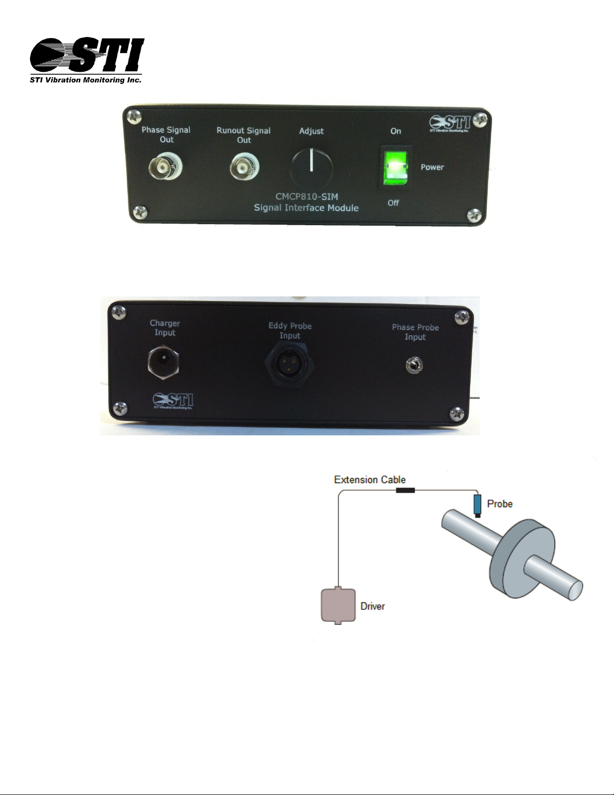
SensorInterfaceModuleSetup:
ConnecttheProximityProbetotheProximityProbeDriver
ConnecttheProximityProbeDrivertotheCMCP810‐SIMusingthe3WiretoM12Adapter
BesureCMCP810‐SIMbatteryischarger.
PlugtheOpticalPhaseReferenceSensorintotheCMCP810‐SIMSocketontheRearPanel
ConnecttheRunoutSignalBNContheSensorInterfaceModuletoChannelAontheOscilloscope
ConnectthePhaseSignalBNContheSensorInterfaceModuletoChannelBontheOscilloscope
TurntheSensorInterfaceModuleOn

CMCP810‐SIMManual
Rev.A.2
www.stiweb.comSTIVibrationMonitoringInc.
LeagueCity,TexasUSA
PublishedJuly2013
Page:4
FlukeScopeMeterSettings:
PriortobeingusedtheScopeMetersettingsmustbeconfiguredtooperatewiththesuppliedrunoutsensors.Thesettings
shouldbeverifiedeverytimetheunitispoweredonastheymayberestoredtodefaultwithoutanynotificationswhenthe
batteryiscompletelydrained.ItissuggestedthattheScopeMeterisregularlycheckedforacharge.Familiaritywiththe
operationoftheScopeMeterisnecessary,refertotheFlukeoperatorstrainingmanualformoreinformation.
FlukeScopeMeterGeneralSetup(FirstMeasurement)
Note:ForthepurposesofmeasuringrunoutChannelA,alsoreferredtoasChannel1isusedwiththeProximityProbefor
takingtheelectricalrunoutmeasurement.ChannelB,alsoreferredtoasChannel2,isusedwiththeopticalsensortoshow
phase(location)relativetotherunout.Toapplythesettings,followthedirectionsbelow(BasedonFluke190‐102
ScopeMeter).
ChannelInputSettings
ChannelASetup(RunoutMeasurementwithProximityProbe):
Pressthe“A”button.
PressF1toturnInputAto“On”
PressF2tochangetoCouplingto“AC”
PressF3toentertheProbeMenu.
UnderProbeTypeselect“Voltage”andpressenter.
UnderAttenuationselect“1:1”andpressenter.
Adjustthe“Range”buttonuntilA~50mV,shownonthebottomleftofthescreen.
ChannelBSetup(PhaseMeasurementwithOpticalSensor):
Pressthe“B”button.
PressF1toturnInputBto“On”
PressF2tochangetoCouplingto“DC”
PressF3toentertheProbeMenu.
UnderProbeTypeselect“Voltage”andpressenter.
UnderAttenuationselect“1:1”andpressenter.
Adjustthe“Range”buttonuntilB~2V.
Scope/WaveformSettings
ChannelASetup(ProximityProbe)
Pressthe“Scope”button.
PressF1toturnReadingsto“On”.
PressF2toenterthe“Reading”menu.
PressF1until“Readings1”ishighlighted.
Usearrowkeystohighlight“onA”andpressenter.
Usearrowkeystoselect“Vac”andpressenter.
ChannelBSetup(OpticalSensor)
Pressthe“Scope”button.
VerifyReadingsin“On”.
PressF2toopenthe“Reading”menu.
PressF1until“Readings2”ishighlighted.
Usearrowkeystohighlight“onB”andpressenter.
Usearrowkeystohighlight“Vdc”andpressenter.

CMCP810‐SIMManual
Rev.A.2
www.stiweb.comSTIVibrationMonitoringInc.
LeagueCity,TexasUSA
PublishedJuly2013
Page:5
MakingtheRunoutMeasurement:
Inordertocollecttherunoutmeasurementtheshaftneedstoberotatedonshaftsupportblockseitherbyhandorby
motorataslowandconstantspeed.
Step1:
VerifyCMCP810‐SIMSensorInterfaceModuleisOnandCablesandSensorsareConnected.
Step2:
AdjusttheProximityProbesDCgapvoltagefora10to12VDCoutput.
Step3:
AdjusttheOpticalSensorsoitdetectsthereflectivetapeoneachshaftrevolution.
Step4:Note–Theshaftmustberotatingfromthisstepforward.
Adjustthe“Time”buttonuntiltherearenomorethanthreeshaftrevolutionsshownonthescreen.Theshaft
revolutionissensedbytheopticalsensoranddisplaysontraceB,theblueline.Thetraceinbetweentwopulses
referencesonefullshaftrevolution.
Step5:
WhentakingtheRunoutmeasurementtheScopeMetershouldbesettoshownomorethanthreeshaft
revolutionsonthescreen.Theshaftrevolutionisshownbythe“B”traceinblue.Tozoominandoutpressthe
“Time”buttonuntilthe“B”traceshowstherevolutionsclearly.TraceAshowingtheelectricalrunoutshouldbe
visibleinbetweentherevolutions,therangesettingoneitherchannelcanbeadjustedtozoominoneitherthe
runoutsignalorphasesignal.Ifthesignalsareoverlappingusethe“Move↑↓”buonstomovethetracesaway
fromeachother.
Step5:
OnceagoodpatternisvisibleontheScopeMeterpressthe“Hold/Run”buttononetime.Tomeasuretheamount
ofelectricalrunoutpressthe“Cursor”buttonthenpressF1toselectthehorizontallines.Usethearrowkeysto
bringthetopandbottomcursorstotheverytopedgeandverybottomedgeoftherunoutsignalinbetweenthe
phasespikesothatthemeasurementistakenduringtheperiodof1shaftrevolutiononTraceA.HitF2toswitch
betweenthetopandbottomlines.
Note:Iftherunoutsignalisnotdisplayedontheoscilloscopescreen,adjusttheDCoffsetontheCMCP810‐SIM
SensorInterfaceModule“Adjust”knobineitherdirectionuntilthesignalisdisplayedonthescreen.
Step5:
Afterthecursorshavebeenplacedatthetopandbottomoftherunoutsignal,theScopeMeterwillcalculatethe
totalamplitudebetweenthetwolinesanddisplayitatthetopofthescreeninmillivolts.Theoutputofthe
proximityprobeis200mV/milon4140seriessteel.TocalculatetototalamountofrunoutdividetheScopeMeters
readingbytheoutputcalibrationoftheprobe.Seepage6forsamplescreenshot.
Ex. ScopeMeterReads52mV
52÷200=0.26milsofelectricalrunout
Step6:
Savethefilebypressingthe“Save”Button.Eachsavewillenteratimestampandwillallowtheusertoprovidea
projectname.
Note:TheScopeMeter’ssetupcanalsobesavedsothateachtimetheScopeMeterispoweredontheusercan
simplyrecallthesetupbypressingthe“Save”buttonandselecting“Recall”.AnexternalUSBdrivecanalsobeused
tosavethefileforeasyPCtransfers.RefertotheFlukeusermanualformoreinformationontheScopeMeterand
FlukeViewsoftwarefunctions.
API670onRunout:
“Thecombinedtotalelectricalandmechanicalrunoutdoesnotexceed25percentofthemaximumallowedpeaktopeak
vibrationamplitudeor0.25mil(6micrometers),whicheverisgreater.Theshaftsurfacefinishshouldbefrom16to32
microinches(0.4to0.8micrometers)rootmeansquare.”

CMCP810‐SIMManual
Rev.A.2
www.stiweb.comSTIVibrationMonitoringInc.
LeagueCity,TexasUSA
PublishedJuly2013
Page:6
RunoutReduction:
DiamondBurnishing
Adiamondburnishingtoolisusedtoworktheshaftsurfaceintoauniformfinish.
Degaussing
Residualmagnetisminashaftcancausemajorelectricalrunoutandcancauseunstablerunoutreadings.Itis
necessarytomeasurethemagnetismtoensurethatitisnotover2.0gaussoriftheareahasvariationsover1.0
gauss.Ifeitherisfoundtheshaftshouldbedegaussed.TheCMCP810SeriesRunoutKitcanbesuppliedwiththe
optionalGaussMeter.
FurtherMachining
Iftheamountofrunoutcannotbereducedwithadiamondburnishingtoolthenthetargetareacanbereground.
Polishing
Similartodiamondburnishingbutnotashighlyeffective.
ProximityProbeSensitivitywithAlternateMaterials:
AllstandardProximityprobesarecalibratedto4140seriessteel.Whenmeasurementsneedtobetakenondifferentshaft
materialsthetrueProximityprobesensitivityneedstobeknowninordertocalculatetheproperelectricalrunoutreading.
Tomeasuretheprobessensitivitywithspecificmaterialsfollowthestepsbelow.
Step1:
Usingplasticfeelergauges,orothernon‐metallicmaterials,placea60milthickpieceofmaterialbetweentheprobetipand
theshaftandmeasurethemillivoltoutputfromthedriver.Recordthis
voltage.
Step2:
Adda10milthickpieceofmaterialontopofthe60milpieceand
measuretheoutputdriver.Recordthisvoltage.
Step3:
Adda5milthickpieceofmaterialontopofthe60miland10milpieces
andmeasuretheoutputfromthedriver.Recordthisvoltage.
Step4:
Takethetotalmeasurementinmillivolts(mV)anddivideby15.Thisistheprobessensitivitytobeusedforcalculatingthe
totalrunoutwiththatspecificmaterial.
Ex.15mils=1350mV
1350÷15=90mV/mil
ProximityProbeConformanceCheck:
AllProximitySystems(Probe,CableandDriver)shouldbetestedeveryonceinawhileto
ensuretheprobeisstilloperateswithinitsspecifiedrange.Thiscanbedonebyusinga
CMCP610StaticCalibrator(soldseparately),‐24VDCPowerSupplyandaDigitalVoltMeter.
TheProbeisinstalledinthetesterwiththetargetsetagainsttheProbetip.The
micrometerwithtargetattachedisthenrotatedawayfromtheProbein0.005"or5mil
increments.Thevoltagereadingisrecordedandgraphedateachincrement.TheCMSS601
Calibratorwillproduceavoltagechangeof1.0VDC+‐0.05VDCforeach5milsofgap
changewhilethetargetiswithintheSystemslinearrange.

CMCP810‐SIMManual
Rev.A.2
www.stiweb.comSTIVibrationMonitoringInc.
LeagueCity,TexasUSA
PublishedJuly2013
Page:7
CMCP810SeriesRunoutKitSetupandConnections(ProvidedwithKit)
ScreenshotDescription:
ScreenshotfromFlukeScopeMeteraboveShows0.3milsofElectricalRunout
68.0mV÷200mV/mil=0.3milsofelectricalrunouton4140seriesshaft.

CMCP810‐SIMManual
Rev.A.2
www.stiweb.comSTIVibrationMonitoringInc.
LeagueCity,TexasUSA
PublishedJuly2013
Page:8
Ifyouhaveanyquestionorrequiretechnicalsupportpleasefeelfreetocontactourtechnicalservicesgroup.
STIVibrationMonitoringInc.
LeagueCity,TexasUSA
Tel.:281.334.0766
Fax:281.334.4255
Other manuals for CMCP810 Series
1
This manual suits for next models
1
Table of contents
Other STI Accessories manuals