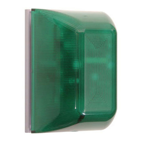
DRILL (4) 3/16 in. DIA. HOLES IF USING #8-10 ANCHORS.
DRILL (4) 3/32 in. DIA. HOLES WHEN USING #6 SCREWS ONLY.
19018 ANCHOR
#8-10
(4) PROVIDED
SUB-71100A-W
19039 SCREW
#6 x 1 1/4 in.
(4) PROVIDED
19060 SCREW
#6-32 x 1 in.
(2) PROVIDED
BASE PLATE
1-24-11
NOTE TO BECK:
This sketch replaces
(Step 5 - Mounting Options VIEW A)
in STI-SA5000 install sheet.
1. Using 5/32 Drill, Drill through the (4) exsisting holes in backbox (one in each corner).
2. Place backbox on wall and mark the mounting hole positions.
3. If using #8-10 anchors, drill 3/16 dia. holes 1 in. deep into wall and press anchor into hole.
If using #6 screws only, drill 3/32 dia. holes 1-1/4 in. deep.
4. Mount backbox to wall using #6 x 1 1/4 screws.
5. Mount base plate as shown using (2) #6-32 x 1 in. screws.
NOTE: If not using STI backbox, make sure surface will depress tamper switch.
ENCLOSURE
ROUTE THE TWO KEY
SWITCH WIRES THROUGH
THE HOLE AS SHOWN
WIRE ACCESS
HOLE
ROUTE THE TWO REED
SWITCH WIRES FROM
CABINET THROUGH THE
HOLE AS SHOWN
**Shipped with jumper wire
installed. Remove to add key
switch or other main power
on/off switch.
Step 5 - Mounting Options
A) To STI Backbox KIT-71100A-W
1.Using 5/32 drill, drill through the (4) existing holes in back box (one in each corner).
2.Place back box on wall and mark the mounting hole positions.
3.If using #8-10 anchors, drill 3/16 dia. holes 1 in. deep into wall and press anchor into hole. If using
#6 screws only, drill 3/32 dia. holes 1 ¼in. deep.
4.Mount back box to wall using #6 x 1 ¼in. screws.
5.Mount base plate as shown using (2) #6-32 x 1 in. screws.
Note: If not using STI back box, make sure surface will depress tamper switch.
A
REMOVE THESE TABS
FROM ALL FOUR
CORNERS
#6 x 1 1/4 in. SCREW
(4) PROVIDED
#6-32 X 5/8 in. SCREW
(2) PROVIDED
BASE PLATE
DRILL (4) 3/16 in. DIA. HOLES
IF USING #8-10 ANCHORS
DRILL (4) 3/32 in. DIA. HOLES
WHEN USING #6 SCREWS ONLY
#8-10
ANCHOR
(4) PROVIDED KIT-SA504
BACKBOX
DETAIL A
“DC IN” are the only polarity sensitive
terminals. When external power is used, battery
will act as a backup. “Dry Contacts: NC, COM,
NO” are used for remote alarm monitoring.
If using power only to trigger alarm,
add jumper to the alarm switch
terminals. If not using key switch or
other main power on/off, key switch
must also have jumper.
