12
English
11
Operation
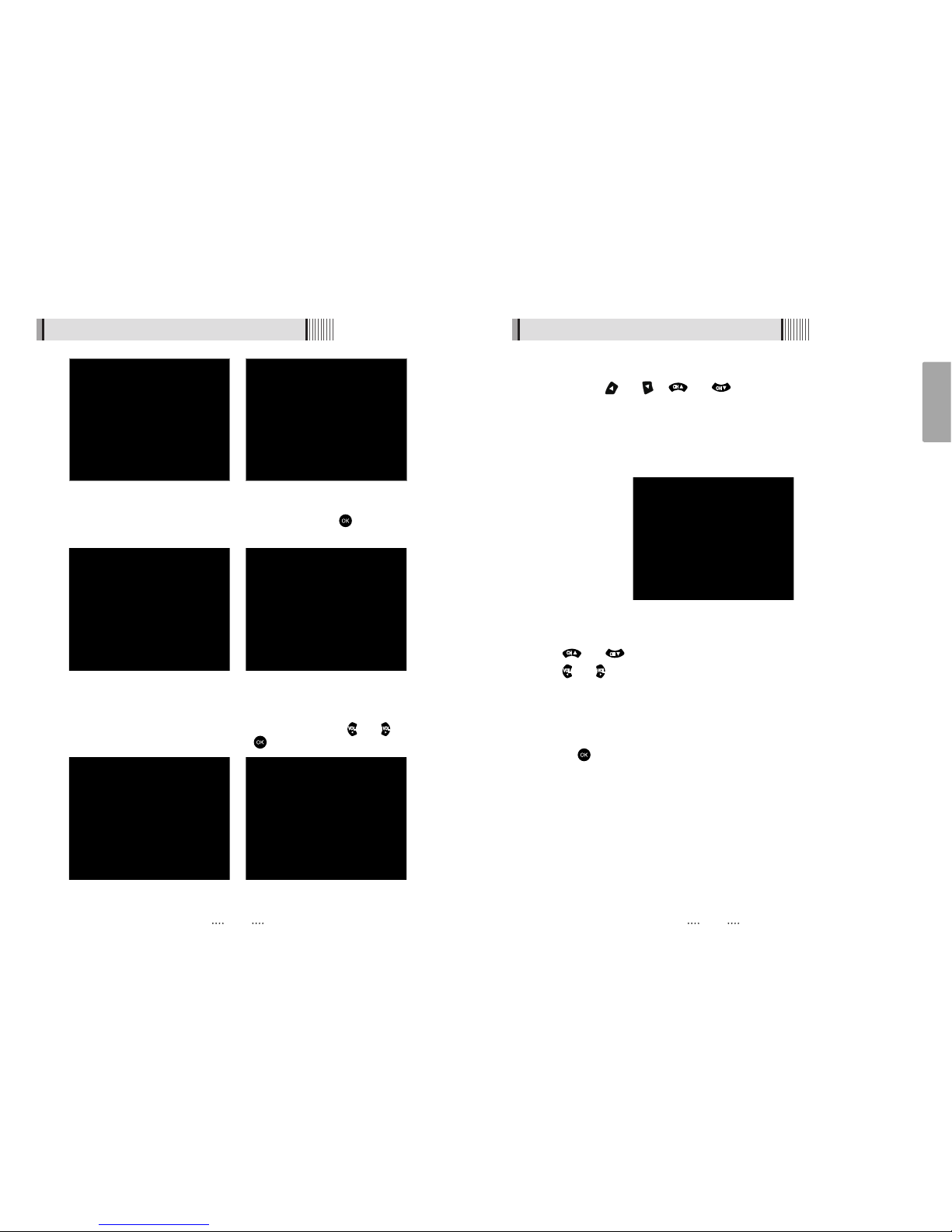
6.1 Getting Started
<Figure 6.1.1> <Figure 6.1.2>
After your receiver is powered on, proceed with installation as follows :
1) Installation Wizard
⊹Plug in the receiver and position the power switch to “on”
⊺Turn on your TV
⊻A pop-up menu will appear for language selection <Figure 6.1.1> Select the desired
language and press button to proceed
⊼The AV output setting menu will now appear <Figure 6.1.2>. Use the / to
select the desired settings and press button to proceed (see also Page 19)
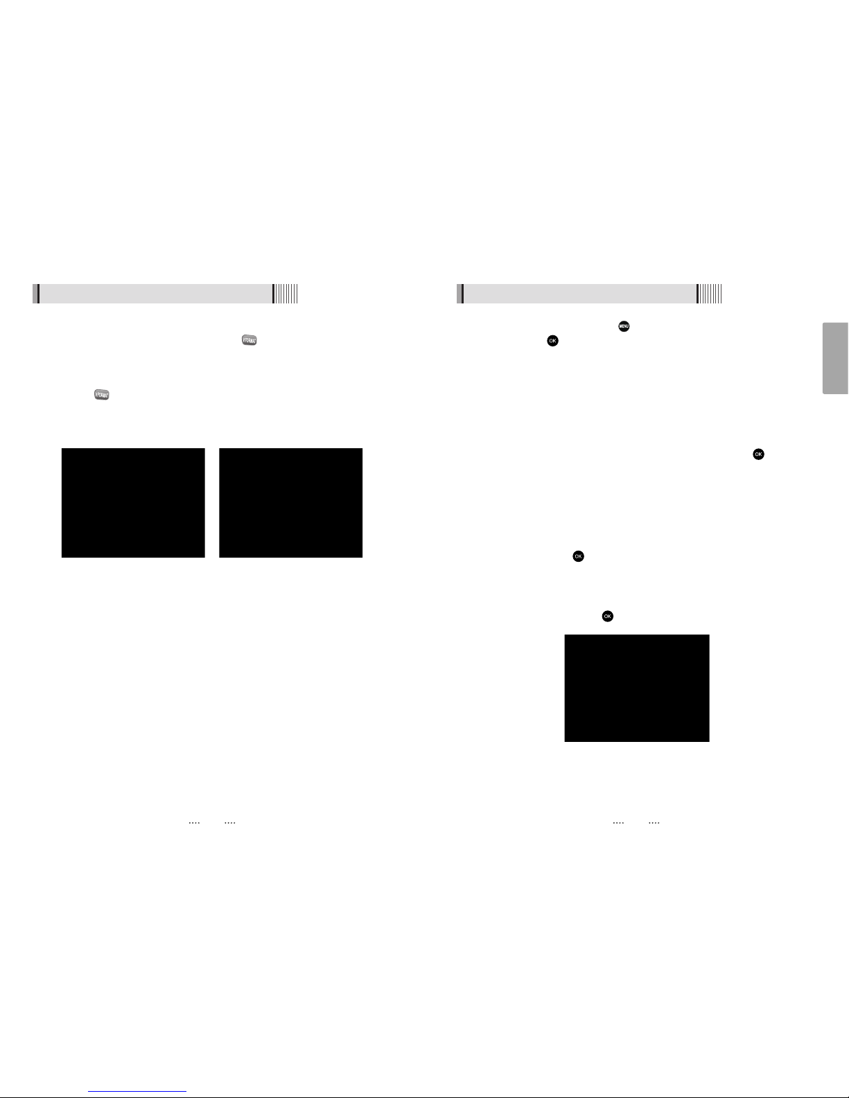
⊽The time setting menu will now be displayed <Figure 6.1.3>. Once again use the
/ to select the desired time and confirm by pressing button.
(see also Page 18)
⊾The Auto Scan menu will now appear <Figure 6.1.4> In this mode the receiver will
scan for all available channels and save them.
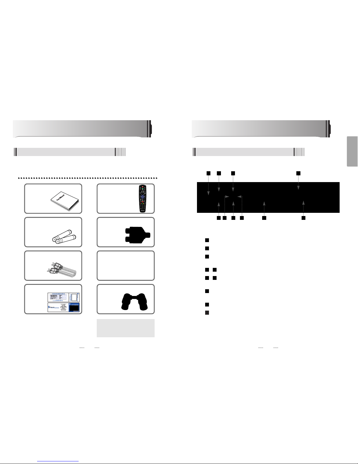
How to Connect
Connect the antenna lead coming from the wall plate to the input marked “Tuner 1”
Connect the Loop Cable provided to the input marked Tuner 1 RF then to the Tuner 2
input as shown in the diagram below
There are a number of methods to connect your receiver to your television
A. Using the Composite cable provided ( red, white and yellow leads)
For video, connect the yellow lead to the yellow socket on back of the receiver
and to the corresponding Video Input socket on the back of the TV.
For Right Audio, connect the red lead to the red socket on the back of the
receiver and to the corresponding Right Audio Input socket on the back of the TV.
For Left Audio, connect the white lead to the white socket on the back of the
receiver and to the corresponding Left Audio Input socket on the back of the TV.
B. Using the Component cable (Sold separately) (green, blue and red leads) paying
attention to the color coding, connect the three color coded leads to the
matching sockets in the back of the receiver and Video Out sockets of the TV. You
will also need a connection for Right and Left audio via the audio socket. This may
be achieved using the Composite cable supplied and connecting the red and
white leads as described in Step A above.
C. If your TV has a HDMI input, you can use a HDMI cable ( sold separately) from the
back of the receiver to the TV. A HDMI cable supplies both video and audio signals
through a single cable so no other leads are required. Please ensure your TV is set
to the HDMI input mode to detect the receiver.
3
2
1