Stuv TULOX 100 User manual

TULOX 100
DE • Montageanleitung
EN • Installation Instructions
www.stuv.de
TULOX 200
Nähere Informationen zur Bedienung fi nden Sie in der gesonderten Bedienungsanleitung
Please refer to the instruction manual for detailed information about the operation

- 02 - Steinbach & Vollmann GmbH & Co. KG • 42579 Heiligenhaus
DEUTSCH
Inhalt
Verwendung, Grundsätzliches 02
Technische Hinweise 03
Montageablauf, Variante 1 04
Montageablauf, Variante 2 07
Zeichnung Einbausituation TULOX 100 16
Zeichnung Einbausituation TULOX 200 18
Verwendung
STUV - Produkte sind für höchste Anforderungen und größtmögliche Zuverlässigkeit konstruiert.
Anwendungs- und Einbauempfehlungen sowie unsere umfangreiche Beratung unter-
stützen Sie bei der Auswahl unserer Produkte.
STUV - Hochsicherheitsschlösser der Typenreihe 4.17.10 sind zur Verwendung an Türen von
Wertbehältnissen gedacht. Prüfung und Eignung für den jeweiligen Anwendungsfall
obliegen immer dem Anwender!
Veränderungen an den Produkten führen zum Verlust der VdS-Zulassung und etwaiger
Garantie- und Gewährleistungsansprüche.
Grundsätzliches:
Die exakte Riegelwerkpositionierung und -befestigung hat wesentlichen Anteil an einer einwand-
freien Funktion des Schlosses. Das Riegelwerk muss sowohl horizontal als auch vertikal exakt aus-
gerichtet sein.
Das Schloss mit Notschlüssel darf nur rechts und in Lad-Stellung (Riegelposition vertikal) eingebaut
werden. Andere Montagepositionen können zu Schließstörungen führen.
Montageanleitung TULOX 100 + 200

- 03 -Steinbach & Vollmann GmbH & Co. KG • 42579 Heiligenhaus
Montageanleitung TULOX 100 + 200
DEUTSCH
- 03 -
Technische Hinweise:
Riegelkopfabmessungen 25,4 mm x 8,3 mm x 10,0 mm
Riegelhub 10,0 mm
Befestigungsschrauben 3 Zylinderschrauben DIN EN ISO 4762 - M6 x 35 mm - 8.8
Alternativ: 3 Zylinderschrauben BSW ¼“ x 35 mm
Lochbild Siehe hierzu Bild 1
Anzugsdrehmoment 9 Nm
Schraubensicherung Es muss eine Schraubensicherung durch Sicherungsscheiben oder
fl üssige Schraubensicherungsmittel erfolgen. Die Einschraubtiefe
muss den gültigen Normen entsprechen
Riegelwerkanbindung Eine Anbindung an das Riegelwerk oder eine Befestigung von
zusätzlichen Blockierelementen darf nur erfolgen, wenn der Riegel-
kopf vom Hersteller stirnseitig eingebrachte M4 Kernlochbohrungen
aufweist.
Schutz des Schlosses Das Wertbehältnis sollte vorzugsweise aus einer Stahlkonstruktion
bestehen, welche geeignet ist, das Schloss gegen Anbohren, z. B.
durch Einsatz von Manganstahl, und Abschlagen, z. B. durch
Abstützung des Schlosskastens, ausreichend zu sichern. Das
Schlüsselloch der Wertbehältnistür und der Panzerung darf
die dargestellten Schlüssellochmaße (Bild 1) nicht überschreiten.
Bei Verwendung von Schlosstypen ohne zusätzliche mechanische
Redundanz (d.h. ohne Schlüssel) kann anstelle des Schlüsselloches
eine Bohrung von Ø 9 mm benutzt werden.
Das Wertbehältnis muss konstruktiv so gestaltet sein, das für
Unbefugte bei offen stehender Tür, keine Zugriffsmöglichkeit auf
sicherheitsrelevante Teile des Schlosses besteht.
Schlossbelastbarkeit Die Freigängigkeit des Riegels im Schließbetrieb muss gewährleistet
sein. Bei Verwendung von Stangen, Winkeln oder ähnlichen, dem
Riegel anhängigen Blockierelementen, müssen Quer- bzw.
Reibungskräfte auf den Schlossriegel durch konstruktive Maßnahmen
vermieden werden. Das Schloss ist mit einer Betätigungskraft von
2,5 N geprüft.
Die Sperrkraft in Betätigungsrichtung und quer zum Riegel ist über
10.000 Schließzyklen mit 1 kN geprüft. Höhere Sperrkräfte sind, z.B.
durch Abstützung des Riegels, abzufangen.
Montageanleitung TULOX 100 + 200

- 04 - Steinbach & Vollmann GmbH & Co. KG • 42579 Heiligenhaus
Montageanleitung TULOX 100 + 200
DEUTSCH
Bild 1
Montageablauf
Variante 1
Wenn Sie das Kabel durch eine separate Bohrung in den Innenraum des Wertbehältnisses führen,
müssen Sie hierfür eine geeignete Bohrposition festlegen, die den VdS-Richtlinien entspricht.
Achten Sie in jedem Fall darauf, dass die Bohrung nicht im Bereich des dahinter liegenden Schlos-
ses liegt und dass die Bohrung später von der Tastatur abgedeckt wird.
Es muss sichergestellt sein, dass das Verbindungskabel beim Einbau nicht gequetscht und seine
Isolierung nicht beschädigt wird (Bild 2)
Notwendige Montagehöhe 37 mm
Schlüsselloch

- 05 -Steinbach & Vollmann GmbH & Co. KG • 42579 Heiligenhaus
Montageanleitung TULOX 100 + 200
DEUTSCH
Bild 2
Achten Sie darauf, dass das Kabel um den Schrauben-
kopf gelegt wird und nicht eingeklemmt werden kann.
Die Sperrrichtung des Schlosses kann der erforderlichen Einbausituation angepasst werden. Hierzu
werden die Feder und das Zahnrad aus der Grundplatte entfernt. Das Zahnrad kann jetzt in 90° -
Schritten in die gewünschte Position gedreht und beide Teile wieder montiert werden (Bild 3).
Bild 3
Zahnrad
Feder

- 06 - Steinbach & Vollmann GmbH & Co. KG • 42579 Heiligenhaus
Montageanleitung TULOX 100 + 200
DEUTSCH
1. Schrauben Sie das Schloss mit 3 Zylinderkopfschrauben M6 x 35 oder BSW ¼“ x 35 fest an.
Hierbei ist das Muttergewinde des Riegelwerks zu beachten. Die Schrauben müssen sich von
Hand leicht ansetzen lassen.
2. Führen Sie das Kabel durch die von Ihnen ausgeführte Bohrung in der Wertbehältnistür und
stecken Sie den Kabelstecker auf der Rückseite des Schlosskastens in die dafür vorgesehene
Buchse.
3. Stecken Sie die Achse durch das Schlüsselloch bis zum Anschlag in den Schlosskasten.
4. Markieren Sie die Achse zum Kürzen ca. 9 bis 10 mm vor der Außenfl äche der Wertbehältnistür.
5. Ziehen Sie die Achse aus dem Schloss, kürzen Sie diese an der markierten Stelle und setzen
Sie sie wieder in den Schlosskasten ein.
6. Stecken Sie die Grundplatte der Tastatur auf die Achse und richten Sie diese senkrecht aus.
7. Kennzeichnen Sie die Bohrposition für die Befestigungsschrauben.
8. Nehmen Sie die Grundplatte wieder vollständig ab und bohren Sie die Befestigungsbohrungen
mit einem Spiralbohrer Ø 3,5 mm. Eine Verschmutzung der Grundplatte durch Bohrspäne ist
unbedingt zu vermeiden.
9. Stecken Sie die Grundplatte wieder auf, wobei Sie die überschüssige Kabellänge auf
die Schrankinnenseite ziehen. Schrauben Sie die Grundplatte mit den beigefügten
Zylinderkopfschrauben an. Hierbei darf sich die Wandung der Grundplatte nicht verformen.
10. Legen Sie die Batterien (4 x 1,5V, AA, Mignon, LR6) unter Beachtung der Polrichtung ein und
setzen Sie die Abdeckkappe auf den Grundkörper auf.
11. Prüfen Sie die ordnungsgemäße Funktion gemäß der Bedienungsanleitung bei geöffneter Tür.

- 07 -Steinbach & Vollmann GmbH & Co. KG • 42579 Heiligenhaus
Montageanleitung TULOX 100 + 200
DEUTSCH
Bild 4
Tastatur
Variante 2
Wenn Sie das Kabel durch die Achse führen, halten Sie bitte den nachfolgenden Ablauf ein.
1. Schrauben Sie das Schloss mit 3 Zylinderkopfschrauben M6 x 35 oder BSW ¼“ x 35 fest an.
Hierbei ist das Muttergewinde des Riegelwerks zu beachten. Die Schrauben müssen sich von
Hand leicht ansetzen lassen.
2. Stecken Sie die Achse durch das Schlüsselloch bis zum Anschlag in den Schlosskasten.
3. Markieren Sie die Achse zum Kürzen ca. 9 bis 10 mm vor der Außenfl äche der Wertbehältnistür.
4. Ziehen Sie die Achse aus dem Schloss und kürzen Sie diese an der markierten Stelle.
5. Fädeln Sie das Kabel in die Achse ein (Bild 4).
6. Schieben Sie die Achse und das Kabel durch die Wertbehältnistür in den Schlosskasten.
7. Ziehen Sie das Kabel auf der Rückseite des Schlosskastens so weit heraus, dass die Grund-
platte auf der Wertbehältnistür aufl iegt. Hierbei müssen Sie die Achse in die Grundplatte ein-
schieben.
Achse

- 08 - Steinbach & Vollmann GmbH & Co. KG • 42579 Heiligenhaus
Montageanleitung TULOX 100 + 200
DEUTSCH
8. Richten Sie die Grundplatte senkrecht aus und markieren Sie die Bohrpunkte für die Befesti-
gungsbohrungen.
9. Nehmen Sie die Grundplatte wieder vollständig ab und bohren Sie die Befestigungsbohrungen
mit einem Spiralbohrer Ø 3,5 mm. Eine Verschmutzung der Grundplatte durch Bohrspäne ist
unbedingt zu vermeiden.
10. Stecken Sie die Grundplatte wieder auf, wobei Sie die überschüssige Kabellänge auf die
Schrankinnenseite ziehen. Schrauben Sie die Grundplatte mit den beigefügten Zylinderkopf-
schrauben an. Hierbei darf sich die Wandung der Grundplatte nicht verformen.
11. Stecken Sie den Kabelstecker auf der Rückseite des Schlosskastens in die dafür vorgesehene
Buchse.
12. Legen Sie die Batterien (4 x 1,5V, AA, Mignon, LR6) unter Beachtung der Polrichtung ein und
setzen Sie die Abdeckkappe auf den Grundkörper auf.
13. Prüfen Sie die ordnungsgemäße Funktion gemäß der Bedienungsanleitung bei geöffneter Tür.

- 09 -Steinbach & Vollmann GmbH & Co. KG • 42579 Heiligenhaus
Installation Instructions TULOX 100 + 200
ENGLISH
Content
Application, Basics 10
Installation procedure, Version 1 11
Installation procedure, Version 2 14
Installation drawing TULOX 100 16
Installation drawing TULOX 200 18

- 10 - Steinbach & Vollmann GmbH & Co. KG • 42579 Heiligenhaus
Installation Instructions TULOX 100 + 200
ENGLISH
Application
STUV - Products are designed for highest demands and maximum reliability.
Application and installation recommendations and our comprehensive consulting service
provide support for the choice of our products.
STUV - High security locks of the 4.17.10 series are intended for use on doors of secure storage
units. Res ponsibility for verifi cation and suitability for the respective application resides
with the user!
Changes to the products lead to the loss of the VdS* approval and any guarantee and
warranty claims.
Basics:
The precise position and mounting of the locking mechanism play a major role in the correct func-
tioning of the lock. The locking mechanism must be aligned precisely in both horizontal and vertical
position.
The lock must be attached with three cylinder head screws M6 or BSW ¼”. The length of engage-
ment of the screw must comply with valid standards. It must be ensured that the fi xing is secured
against unintended loosening. Vibration or concussion must not lead to a loosening of the fastening.
The lock with emergency key may only be installed on the right and in load position (vertical bolt
position). Other installation positions may lead to closing problems.
When installing the lock in secure storage units attention must be paid to adequate protection
against forcible external attacks. The key hole of the secure storage unit door and the armouring
may not exceed the shown key hole dimensions (Figure 1). When using lock types without additional
mechanical redundancy (i.e. without key) a drilled hole with Ø 9 mm can be used instead of the key
hole.
*VdS: German independent testing institution

- 11 -Steinbach & Vollmann GmbH & Co. KG • 42579 Heiligenhaus
Installation Instructions TULOX 100 + 200
ENGLISH
Figure 1
The ease of movement of the bolt in locking mode must be guaranteed. When using bars, angles
or similar blocking elements attached to the bolt, transverse forces, resp. friction on the lock bolt
must be avoided through construction measures. The lock has been tested with an actuating force
of 2.5 N.
The locking force in actuating direction and transverse to the bolt has been tested with 1 kN. Higher
locking forces must be compensated e.g. by supporting the bolt.
Installation procedure
Version 1
If you wish to route the cable through a separate drill hole into the inside of the secure storage unit,
you need to determine a suitable drilling position which corresponds with the VdS guidelines.
Pay careful attention that the drill hole is not positioned in the proximity of the lock situated behind
it and that the drill hole is later covered by the keypad.
It must be ensured that the connecting cable is not crimped during installation and the insulation is
not damaged (Figure 2).
Necessary assembly height 37 mm
Key hole

- 12 - Steinbach & Vollmann GmbH & Co. KG • 42579 Heiligenhaus
Installation Instructions TULOX 100 + 200
ENGLISH
Figure 2
Pay attention that the cable is positioned around the
screw head and cannot be jammed.
The locking direction of the lock can be adjusted to the required installation situation. The spring
and the cogwheel must be removed from the base plate for this purpose. The cogwheel can now
be turned in the desired position in 90° steps and both parts can then be re-assembled (Figure 3).
Figure 3
Cogwheel
Spring

- 13 -Steinbach & Vollmann GmbH & Co. KG • 42579 Heiligenhaus
Installation Instructions TULOX 100 + 200
ENGLISH
1. Screw the lock on tightly with 3 cylinder head screws M6 x 35 mm or BSW ¼“ x 35 mm.
Consider the female thread of the bolt work. The insertion of the screws must be without
force.
2. Lead the cable through the drill hole you have prepared in the secure storage unit door and
plug the cable connector on the rear side of the lock case into the provided jack.
3. Insert the axis through the key hole into the lock case.
4. Mark the axis for shortening approx. 9 to 10 mm in front of the external surface of the secure
storage unit door.
5. Pull the axis out of the lock, shorten it at the marked point and then re-insert it in the lock
case.
6. Plug the keypad´s base plate onto the axis and align it vertically.
7. Mark the drilling position for the fastening screws.
8. Completely remove the base plate again and drill the fastening holes with a spiral drill Ø 3.5
mm. Pay careful attention that the base plate is not contaminated with bore chips.
9. Replace the base plate. Pull the spare cable length into the inside of the unit. Attach the base
plate with the enclosed cylinder head screws. The wall of the base plate must not deform
during this process.
10. Insert the batteries (4 x 1.5V, AA, LR6) paying attention to the terminal direction and place the
cover on the base plate.
11. Check the proper function in accordance with the Operating Instructions with the door open.

- 14 - Steinbach & Vollmann GmbH & Co. KG • 42579 Heiligenhaus
Installation Instructions TULOX 100 + 200
ENGLISH
Version 2
If you wish to lead the cable through the axis, please follow the sequence described below.
1. Screw the lock on tightly with 3 cylinder head screws M6 x 35 mm or BSW ¼“ x 35 mm.
Consider the female thread of the bolt work. The insertion of the screws must be without
force.
2. Insert the axis through the key hole into the lock case.
3. Mark the axis for shortening approx. 9 to 10 mm in front of the external surface of the secure
storage unit door.
4. Pull the axis out of the lock and shorten it at the marked point.
5. Thread the cable into the axis (Figure 4).
Figure 4
6. Slide the axis and the cable through the secure storage unit door into the lock case.
7. Pull out the cable on the rear side of the lock case until the base plate lies on the secure stor-
age unit door. You need to insert the axis into the base plate to do this.
Keypad
Axis

- 15 -Steinbach & Vollmann GmbH & Co. KG • 42579 Heiligenhaus
Installation Instructions TULOX 100 + 200
ENGLISH
8. Align the base plate vertically and mark the drilling position for the fastening screws.
9. Completely remove the base plate again and drill the fastening holes with a spiral drill Ø 3.5
mm. Pay careful attention that the base plate is not contaminated with bore chips.
10. Replace the base plate. Pull the spare cable length into the inside of the unit. Attach the base
plate with the enclosed cylinder head screws. The wall of the base plate must not deform du-
ring this process.
11. Plug the cable connector on the rear side of the lock case into the provided jack.
12. Insert the batteries (4 x 1.5V, AA, LR6) paying attention to the terminal direction and replace the
cover.
13. Check the proper function in accordance with the user manual with the door open.

- 16 - Steinbach & Vollmann GmbH & Co. KG • 42579 Heiligenhaus
Anhang / Appendix
Mittelpunkt Achse = Mittelpunkt Schlüsselloch
axis centre = keyhole centre

- 17 -Steinbach & Vollmann GmbH & Co. KG • 42579 Heiligenhaus
Anhang / Appendix

- 18 - Steinbach & Vollmann GmbH & Co. KG • 42579 Heiligenhaus
Anhang / Appendix
Mittelpunkt Achse = Mittelpunkt Schlüsselloch
axis centre = keyhole centre

- 19 -Steinbach & Vollmann GmbH & Co. KG • 42579 Heiligenhaus
Anhang / Appendix

Steinbach & Vollmann
GmbH & Co. KG
Schloß- und Beschlägefabrik
Parkstraße 11
42579 Heiligenhaus
Germany
Telefon +49 2056 14-0
Telefax +49 2056 14-251
E-Mail info@stuv.de
Internet www.stuv.de
04/2015 Printed in Germany.
Zumutbare Abweichungen in Model-
len und Farben sowie Änderungen
zur Anpassung an den neuesten
Stand der Technik und Produktion
bleiben ausdrücklich vorbehalten.
Other manuals for TULOX 100
2
This manual suits for next models
1
Table of contents
Languages:
Other Stuv Lock manuals
Popular Lock manuals by other brands
Borglocks
Borglocks BL2400 Series instruction manual
Simons Voss Technologies
Simons Voss Technologies LockNode MP Z4 quick guide

Yale
Yale Real Living Assure Lock YRD226 Installation and programming instructions
Digilock
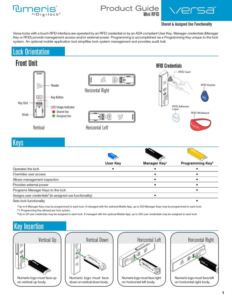
Digilock Numeris Versa Standard Guide

Viro
Viro SPRANGA 4008.E Mounting instructions
Numeris
Numeris Versa Product guide

