sugar-valley UVSCENIC UV 16 User manual

Electronic unit
UVSCENIC
QUICK INSTALATION GUIDE
RCA flow detector
pH probe
Redox probe
Hydrolysis cell
Mains connection 220v.
3.15A fuse
250 mA fuse
ON-OFF switch
Air vent
Acid pump connection
2
3
4
5
6
7
8
9
10
11
DESCRIPTION
1
Vaso ionización (2-4-6e)
Electrodos cobre/plata
Tuerca electrodos
Cable electrodos
1
2
3
4
ph probe
Junta escalonada
Junta tórica
5
6
Conductivity probeRedox probe
Probe
Probe casing
Connection housing
1
2
3
Probe
Probe casing
Connection housing
1
2
3
Probe
Probe casing
Connection housing
1
2
3
1
2
3
1
2
3
1
2
3
Ultraviolet
U.V. lamp 55W
Quartz crystal
White ABS Support
Power transformer
1
2
3
4
Cell
Hydrolysis cell
RCA flow detector
Cell connection
Flow/gas detector
1
2
3
4Cell housing
5
5
4
1
2
3
1.6A fuse
Connection U.V.
14
15
4
3
12
10
7
8
9
6
2
3
4
5
11
10
14 15
Optional extras
With the HYDROLYSIS system we produce active agents like OXYGEN, PEROXIDE, HYDROXYLS, OZONE… on the bases of
Water (H2O - with a minimum conductivity of 1000mS). While the Water passes through the hydrolysis cell these oxidative agents
are produced. This disinfect sand eliminates the organic material present in the water. The generated disinfectants turn back into
H2O whilereturningtothepool.Thesalinityprovidedatstart-up(1.5-2.5g/l)keepsthewaterinperfectconditionwithafreechlorine
residualthatisimperceptibletotheeyesandskin.
UV Scenic supports this process by adding UV light disinfection. the additional exposure of microorganisms and germs to hard UV
light achievesexceptionalcleanfreeofchemicals.

INSTALATION
2
System installation diagram
Electrical housing
1
Filtration pump timer
ASand filter
BRecirculation pump
C
Hydrolysis cell (always in vertical position)
3pH probe(Optional, for models with PH control)
4Redox probe (Optional, for models with redox control)
5Conductivity probe (Optional, for models with conductivity control)
6
11
12
13
10
8
9
15
Electrical consumption
UV 16
UV 33
UV 50
UV 85
UV 125
UV 175
180W
228W
600W
1020W
1440W
1620W
Recommended
protection
Maximum
consumption
UVSCENICsynchronizedwithFILTRACIÓN
Ensurethehydrolysisunitissynchronizedwiththepoolfiltrationandstopsfunctioning
whenwatercirculationhasstopped.
TITANIUMCELLconnectionoverheating
Ensure all electrical connections are firmly fixed to avoid false contacts and
subsequentoverheatingofsystemcomponents(EspeciallyconcerningtheHydrolysis
cellwithusageabove33A).
10A
10A
16A
16A
25A
25A
A
B
C
1
45
13
12
11
10
9
8
min. 1m
15
Chlorine pump
(Optional, for models with redox or free chlorine control + auxiliary chlorine dosage)
Chlorine injector (Optional, for models with redox or free chlorine control)
Chlorine container
(Optional, for models with redox or free chlorine control, not supplied with unit)
Hydrochloric acid container
(optional, for models with PH control, not supplied with unit)
Acid pump (Optional, for models with PH control)
Acid injector (Optional, for models with PH control)
Other pool equipment (pool heating, heat exchanger, etc,)

Electronic housing display
ALARM
Excessive increase or decrease in parameters (+/- 15% from
theselectedparameters).
CHECKLEVELSINACID/BASECONTAINERS
CHECKPROBECALIBRATION
InsufficientFLOWorcelldisconnected
Production halted due to lack of flow, or gas in the titanium cell
detector.
ONLYSYSTEMSWITHFREECHLORINECONTROL(ppm's)
INSUFFICIENTFLOWintheCHLORINEdetector.
The rotary sensor detects insufficient flow. CHECK the rotameter
pendel – and solve the system's hydraulic problem (If there is a
precedingfilterthismustbecleaned).
Conductivity/Celllife
Lowconductivity(Seesection3)
Titaniumcellincrusted(Seecleaningprocessinsection5)
Cellsurfacecorroded(Seesection7)
ONLYSYSTEMSWITHREDOXORFREECHLORINE
The system has automatically stopped as Redox levels are above the
chosenvalues(Seesection5)
Timedelay
Period of non-production while system changes polarity (0-
120sec.)
START UP
4
INITIAL ADJUSTMENTS
3
Water adjustments
1.Adjustthealkalinitybetween90and110ppm.
2.AdjustthePHbetween7,2and7,4
3.Adjustthechlorinebetween1and1,5ppm.
SHOULD the water be supplied from a well: shock
chlorinate with Tricloroisocyanuric acid (2Kg./50m3
ofwater)
Conductivity adjustments
Start up
In poorly conductive waters add 2Kg, of sodium chloride (Salt=NaCl) for
everym3ofpoolwater.
IN POOLS WHICH RECEIVE LARGEAMOUNTS OF STRONG SUNLIGHT
30gr/m3OFSTABILYSER(Isocyanuricacid)MUSTBEADDED
Thiswillnotbenecessaryforcoveredpools.
SYSTEMS WITH REDOX CONTROL
5
The Redox level advises us of the potential oxidization or reduction level and is used to determine the level of water sterilization. The parameters or Set Points are the
minimum/maximumacceptedREDOXlevelsbeforethetitaniumcellisconnected/disconnected.
AdjustingtheidealREDOXlevel(setpoint)isthelaststepintheUVScenicstartupsequence.TofindtheoptimumREDOXlevelforyourpoolfollowthesesteps:
1. Connectthepoolfiltrationsystem(Thesaltinthepoolmustbeadequatelydissolved).
2. Addchlorinetothepooltillalevelof1ppm.isachieved(Approx.1gr/m3ofwater).PHlevelsshouldbebetween7,2and7,5.
3. After30min.testthefreechlorinelevelsinthepool(DPD1manualtestkit)Ifthefreechlorinelevelisbetween0,8-1,0ppm:LookattheREDOXscreenandmemorize
thislevelasthesetpointtoCONNECT/DISCONNECTthehydrolysiscell(Tomemorizethesetpointseesection8)
4. Thenextdaycheckfreechlorinelevels(manualDPD1testkit)and REDOX.Raise/lowersetpointifnecessary.
Status led's
Hydrolysis production
ENTER button
Right button
Left button
Up button
Down button
Operating hours U.V.
pH probe
Conductivity probe /
water temperature
Free Chlorine / Redox
UVLAMP
Lamps have reached 8,000 hours of operation. We
recommendlampreplacement.

MAINTENANCE
6
1-Thepoolmustbevacuumedasusualandtheskimmersemptiedwhenevernecessary.
2-Filter backwashing: with Sugar Valley systems the filter requires only occasional backwashing; once every 20 days should be sufficient (providing the filter pressure does
notexceed1bar,inwhichcaseabackwashmaybenecessary).
3-ADDINGNEW WATER:Always throughtheskimmerssothat thenew waterpassesthrough the beforeentering thepool.Remember toadd thenecessarysalt:
2gr.peraddedlitreofwater.
4-InwinterCHANGINGTHEPOOLWATERISNOTRECOMMENDABLE.Werecommendthatthesystemruns2-3timesperweek(2-3hrs.perday).
DOSAGE PUMPS: Check regularly to ensure that the container contains liquid to prevent the dosage pump running dry. The dosage pump requires maintenance
(INSTRUCTIONSONBOX).
PHPROBES/REDOX/CONDUCTIVITY:Probesmustbecleanedwhenevernecessary(checkevery5-6months).Toclean probe,insert indistilled water(Clear liquid).After
eachcleaningtheprobesmustbecalibrated.
UVScenic
General maintenance
VERY IMPORTANT; Ensure that the Sugar Valley system is turned off during filter backwashing.
FREE chlorine : 1.0 PPM
pH : 7,1 – 7,5
Fortnightly checks
TOTAL(TAC)alkalinity :80-120ppm
Saltconcentration :1.500–2.500ppm
Cyanuricacid :30-50ppm
Titaniumcell :Visualinspectiontodeterminescale.
Monthly checks
CLEANING THE TITANIUM CELL: Maintenance of the disinfection system (hydrolysis) consists of cleaning the cell or electrode every 2-3 months should it appear
necessary(carryoutavisualinspection)Tocleantheelectrode:
-Removethecellfromitssupport(afterturningoffthefiltrationsystemandclosingoffthenecessaryvalves).
-Placetheelectrodefornomorethan10min.in15%HYDROCHLORICACID.
-Oncetheincrustationshavesoftenedremovethemwithahose.
USE NO METALIC OR SHARP OBJECTS TO REMOVE INCRUSTATIONS. Scratching the edges or surface of the cell will make it vulnerable to chemicals, deteriorate the
cellandannultheguarantee.
Titanium cell maintenance
Duringthefirst10-15daysyourpoolsystemwillrequiremoreattentionandthefollowingcare:
1. CHECK THE PH REMAINS BETWEEN THE IDEALLEVELS (7,2-7,4). If the PH is unusually unstableAND USES ALOT OFACID check the alkalinity (Recommended
levelsbetween80and125ppm.).
2.Thepoolmustbevacuumedandtheskimmerscleanedwhenevernecessarytoensureperfectwaterconditions.
REMEMBERthattheSugarValleysystemrequiresacertainamountoftimetoadapttoyourswimmingpoolandwillrequireadditionalchemicalsduringthefirst3-5days.
Initial maintenance
MENU ACCESS
7
q
HOLD FOR 3 SECONDS TO ACCESS
EXIT USER MENU
Accessing user menu
Displays
Conductivity control
5
Redox / Free chlorine control
pH Control
Hydrolysis level
4
3
2
112
3
4
5
U.V.

User menu
pH SET POINTS
To modify parameters/maximum pH set point
To LOWER pH - maximum water pH - CONTROLS THEACID PUMP (optional equipment)
OXIDATION LEVEL
To modify level
To confirm and change menu
To modify parameters/minimum pH set point
To increase pH - minimum water pH - CONTROLS THE base PUMP (optional equipment)
pH PROBE CALIBRATION
Insert probe in pH 7 sample,
wait till reading has stabilized
Clean probe in NEUTRAL.
Insert probe in pH 10
sample and wait till reading
is stable.
Redox SET POINT
To modify parameters / Redox set point To confirm and change menu
REDOX PROBE CALIBRATION
Insert probe into 465mv sample, wait till
reading is stable.
CONDUCTIVITY SET POINT
To modify parameters / conductivity setpoint To confirm and change menu
CONDUCTIVITY PROBE CALIBRATION
Insert the probe in
sample, wait until reading
is stable.
To change menu and
return to Ion menu.
q
Change conductivity
reading to match
sample.
Calibration correct
Repeat calibration or
change probe.
Calibration correct
Repeat calibration or change probe.
Calibration correct
Repeat calibration
or change probe
RECOMMENDED LEVEL: 6,8
RECOMMENDED LEVEL: 7,2 - 7,5
RECOMMENDED LEVEL: MAXIMUM POWER 100%
DISPLAY 2
DISPLAY 3
DISPLAY 4
DISPLAY 5
RECOMMENDED VALUE SEE CHAPTER 5
RECOMMENDED LEVEL: 1.500 - 2.500
OPERATING SYSTEM UV
8
IMPORTANTSAFETYINFORMATION
-NeverlookdirectlyintoalampwhileUVlightisshuton.
-Donotoperatedry.Donotcovertheunit.
-Alwaysdisconnecttheunitfromthepowersupplyandshutthewatersupplyoffbeforeperformingmaintenance.
-Theunitmaynotbeimmersedinwater.
-Ifthequartzsleeveiscracked,replaceitimmediately.
Theunitshouldbeprotectedagainstfrostorstoredinindoorenclosuresduringthewintermonths.
OPERATION
TheUVsystemwilloperatewheneverthefilterpumpisoperating.Theupperleftdisplay(display1)oftheelectronicboxindicatethecumulativehoursofoperationofthelamps.
MOUNTINGONAWALLOROTHERVERTICALSURFACE
This unit can be mounted on a wall or other vertical surface. When the unit is full of water it might be too heavy for mounting on a wooden panel of a conventional fence and
thereforeshouldbemountedonawall.
Caution:Topreventthe unitfromfalling intothewater,donotinstall overoradjacent tothepool.Donotelectricallyconnecttheunituntiltheplumbinghasbeen completedand
issecurelyfixed.
ForoptimalperformancewerecommendthatthetotalvolumeofthepoolwaterpassesthroughtheUVuniteveryfourhours.

TROUBLESHOOTING
9
Display blank
*CheckOn/Offswitchisilluminated.
*Checkexternal250mAfusehasnotfused.
*Checkelectricsupply:210-230V50Hz
*IfproblempersistscontactTECHNICALSERVICE.
Hydrolysis does not reach maximum intensity
*Checksodiumbromideorcommonsaltconcentrationinwater.
*Checkcellstatus(maybeincrustedorcalcified).
*Cleanelectrodefollowinginstructionsinsection6.
*Cleanflowdetectorsituatedinthecellcasing.
*Check titanium cell is not worn (remember that the cell is guaranteed for 5000-6000
hours(approx.2-3yearsofSummerusage)-seetroubleshootingformoreinformation).
Polarity 1 reaches max. intensity but polarity 2 (Auto clean) does not
*IFSALTLEVELISCORRECT(1kg./m3) cellisreachingendoflife.Asofthismomentcheckintensityevery15-30days
*Whenpolarity2doesnotreach50%werecommendsubstitutingcellforanew oneifduring thesummerormaximumusageperiod.Ifthisshouldhappeninwinterchangebefore
thenextseason(summer).
Free chlorine levels don't reach 0,2ppm. First thing in the morning
*INCREASEFILTRATIONtime.
*INCREASEhydrolysislevel.
*Checklevelsofsodiumbromideorcommonsaltinthepool(1gr.NaCl/L).
*Checklevelofisocyanuricacidinpool(30-50ppm.)ONLYifusingCOMMONSALT.
*CheckreactiveagentsintestkitarenotTOOOLD.
*Hasthetemperatureoramountofusersrisen(see3.1/3.2seechapter“Watermaintenance”).
*pHisabove7,8andmustbeadjusted.
Hydrolysis display shows LO
*Waterlacksconductivity(seesection3“waterpreparation”).
*Checkforincrustationsoncell.
*Seetroubleshooting“Hydrolysisdoesnotreachmaximumintensity”.
White flakes in pool
*Thishappensinexcessivelyhardunbalancedwaters.
*Balancethewaterandcheckthecell. cleanitifnecessary.
Hydrolysis display shows FL
*Checkflowdetectorcable.
*Cleanincrustationsofflowdetectorattopofcellcasing.
*Checksystemisfreeofair(Probemustbealwayssubmerged).
RUST on metallic components in pool
*Metallic elements lack standardized earth connection. Contact an electrician to
solve.
*Rustedcomponentsarenotstainlesssteel:
minimum304-recommended316.
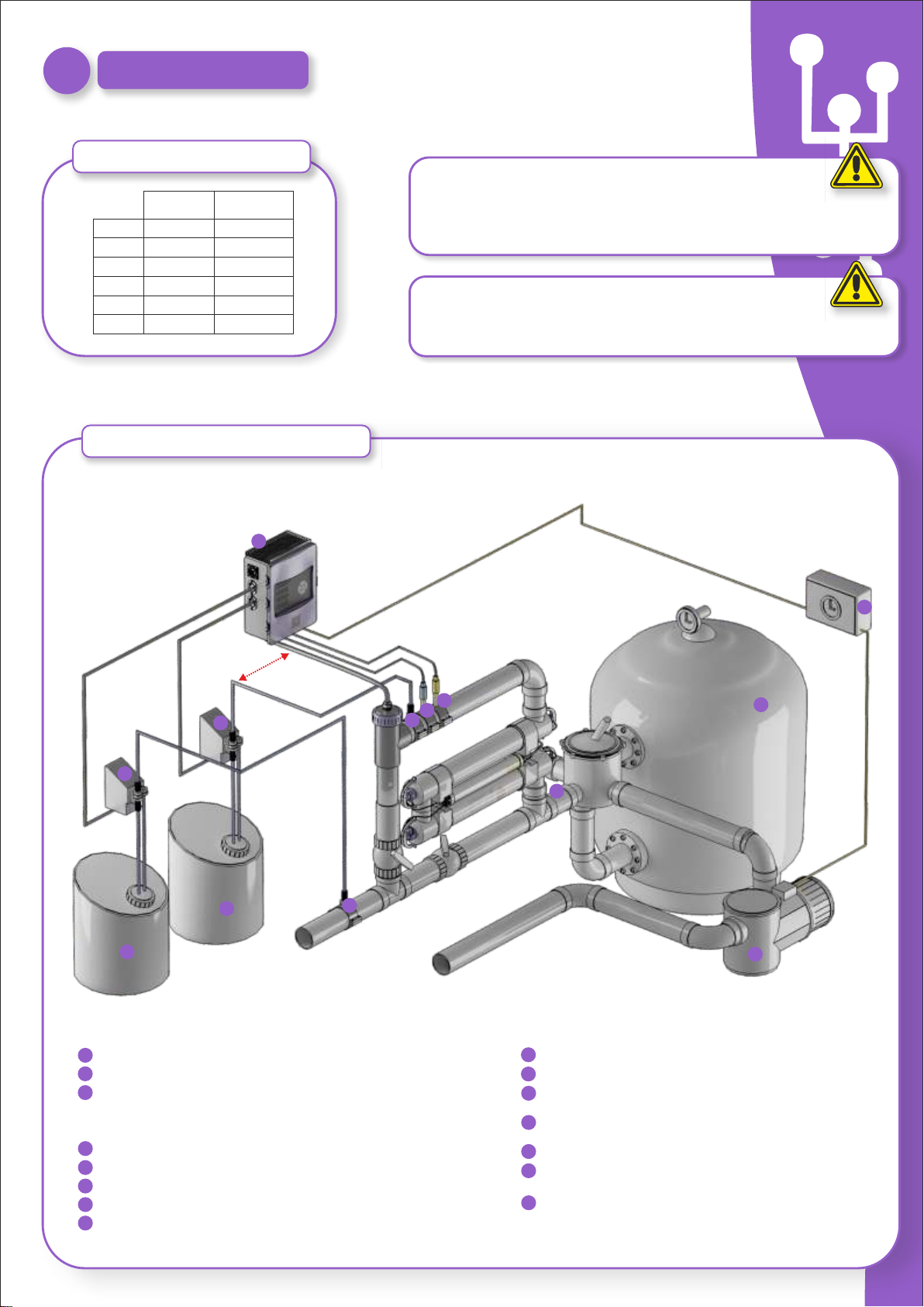
EARTHING
All metallic components in the pool, such as lamps, ladders, heat exchangers, drains or similar elements within 3.00m. from pool (10feet) must be connected to an earth below
37Ohms.
WERECOMMENDHEATEXCHANGERSBEMADEOFTITANIUM.
CLEANINGFILTER
Ensure isNOTRUNNINGduringbackwash.UVSCENIC
VERYIMPORTANT
REMEMBERthatthesystemneedssometimetoadapttoyourpoolandyouwillhavetoincreasechemicallevelsforthefirst5days.
WARNING
Keepchemicallevelsinpoolasinstructedinthismanual
SECURITY
Toavoidaccidentsthisproductshouldnotbehandledbychildrenunlesssupervisedbyanadult.
Childrenshouldbesupervisedatalltimeswheninornearaspa,poolorJacuzzi.
HANDLINGANDDOSINGDANGEROUSCHEMICALS
Chemicalsshould behandledwithextremeprecaution.WhenpreparingACID,ALWAYSADDTHEACIDTOWATER,neveraddwaterto acid!!!VERYdangerousgassesmaybe
produced.
EXCESS OXIDATION in water
*LowerHydrolysislevel.
*If your system includesAUTOMATIC REDOX CONTROL check REDOX
SETPOINT.
*CheckREDOXprobeandcalibrateifnecessary.
Titanium cell incrusted in less than 1 month
*Veryhard waterswithahighpHandtotalalkalinity(Balance wateradjusting
pHandtotalalkalinity).
*Checktoensurethesystemautomaticallychangespolarity(LED'salternate
every300min.approx.).
*CONSULT with our technical service to consider ACCELERATING THE
polaritychange(Auto-cleaning)WARNING:acceleratingthepolaritychange
decreasesthecelllifeproportionally.
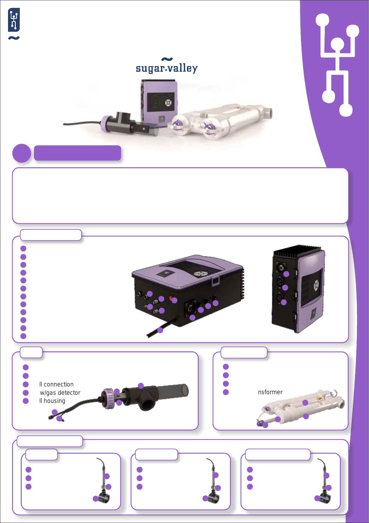
Undernormalconditions,theUVlampsplacedinsidetheUVwilllast1yearor8,000hours.TheupperrightUVscenicdisplay(display1)indicatesthetotalhoursofoperationofthe
UVunit.
If you change de lamps, use new O-rings. When reassembling the unit, make sure the female threads of the compression fittings and male threads of the main structure are
clean.Thenreplaceand firmlyhandtighten the compressionfittings.Replace thelampor fit anew one. Relocatethelampholders and bluelampholder shrouds ensuringthatyou
matchthecorrectnumberedlampholders.
NOTE: Pinch the blue coating of lamp holder, when reassembling the unit, to release trapped air. If not released any trapped air may provoce disconnection of lamp holder.
Reconnectandturnthewatersupplyon,toensuretherearenoleaksbeforeyoureconnectthepowersupply.
Routine Maintenance
This manual suits for next models
5
Table of contents
Other sugar-valley Swimming Pool Cleaner manuals
Popular Swimming Pool Cleaner manuals by other brands

Blue Lagoon
Blue Lagoon UV-C 15.000 manual

Maytronics
Maytronics Ozone Swim Twin Series user manual

Paramount Fitness
Paramount Fitness PCC2000 owner's manual

Hammerhead
Hammerhead DCFSCS22Z Operator's manual

Astral Pool
Astral Pool VIRON QT 1000 owner's manual

Maytronics
Maytronics Dolphin Deluxe 4 User instructions