Foreword
SUMAKE is a manufacturer and exporter of air
tools since established. We have devote all our
efforts in improving quality and tools’ life. As
well as the noise and vibration of tools. Bring all
of you working efficiences, profits, and enjoy
using the tool is our principle.
Features
This air tool is a pneumatic tool that injects high
efficiency into manual chipping, riveting, breaking
of concrete and asphalt etc. Your care in handling
it is, however, important if performance is to be
realized over a long period of time. This booklet is
prepared to equip you with the knowledge
necessary to keep it on the job efficiently.
Operator‘s instruction
1. Cautions for Use
1-1 Air pressure
mechanism, and may cause trouble. So, install a
air filter and an oiler between the compressor an
the tool. Use a 3 HP or larger compressor for eac
sander.
1-3 Air hose
Clean the hose with a blast of compressed ai
efore connecting the hose to air tool. This wil
revent both moisture and dust within the hos
from entering the tool and causing possible rust o
malfunction. To compensate for unusually lon
hose (over 25 ft), the line pressure should b
increased accordingly.
Drainage
1-4 The approved eye protector, ear-muff
chisel
screw
out
screw
in gun body
retainer
2-2 On-off device
Please note that the tool never running unless the
insert tool is properly fixed on the gun body. To
operate this tool, just push the trigger, which is on
the grip, down. The tool continuously reciprocating
as one push the trigger down and it stops running as
thetriggerisreleased.
For the sake of safety, put it on hanger or on a soft
flat pad when not in use.
2-3 Replace and adjusting
There is no userserviceable part inside this tool.
Please sendthetool to aqualified personnel orour
service section to repair or/and replace worn parts.
*In orderingparts and components, give each part
number, name and quantity.
Warning
1. This tool is not insulated for coming into contact
withelectricpower source.
2. It is forbidden to use this tool in explosive
atmospheres and do not put any combustible
material near the workpiece since it might emit
sparks when working on hard material.
3. Check the wear of the insert tool and the retainer
before operating this tool.
4. Working with this tool will generate dust,
depending on the material being worked on,
could be harmful to the operator
5. This tool can cause the ejection of particles at
chipping or demolishing work, hence the
operator shall wear appropriate protective device
and do not let other person near the work area.
6. The insert tool and the retainer on heavy types
are exposed to heavy strains and can after a long
period of use break due to fatigue.
7. Keep your body balance and beware ofthe break
Foreword
SUMAKE is a manufacturer and exporter of air
tools since established. We have devote all our
efforts in improving quality and tools’ life. As
well as the noise and vibration of tools. Bring all
of you working efficiences, profits, and enjoy
using the tool is our principle.
Features
This air tool is a pneumatic tool that injects high
efficiency into manual chipping, riveting, breaking
of concrete and asphalt etc. Your care in handling
it is, however, important if performance is to be
realized over a long period of time. This booklet is
prepared to equip you with the knowledge
necessary to keep it on the job efficiently.
Operator‘s instruction
1. Cautions for Use
1-1 Air pressure
Maximum performance is displayed at the proper
sanding speed, obtainable at a gauge pressure of
6.2 bar. Range-wise, this is an air pressure from 5
to 7 bar (70 to 100 psi)
57
1-2 Air line
Use a 3/8“ air hose between the compressor and
the tool . Compressed air is cooled and its water
content separated, as soon as the air leaves the
compressor.
Tool
Nipple
Coupler Recoil
hose
Leader
hose
Oiler Regulator
Water
separation Air
supply
Drain
daily
mechanism, and may cause trouble. So, install a
air filter and an oiler between the compressor an
the tool. Use a 3 HP or larger compressor for eac
sander.
1-3 Air hose
Clean the hose with a blast of compressed ai
efore connecting the hose to air tool. This wil
revent both moisture and dust within the hos
from entering the tool and causing possible rust o
malfunction. To compensate for unusually lon
hose (over 25 ft), the line pressure should b
increased accordingly.
Drainage
1-4 The approved eye protector, ear-muff
mouth-muffle, and gloves should be worn whe
operate this tool.
1-5 The working place shall be well ventilated.
1-6 Release the on-off device in the case o
energy supply failure.
2. Operation, Adjusting And Replacin
Method
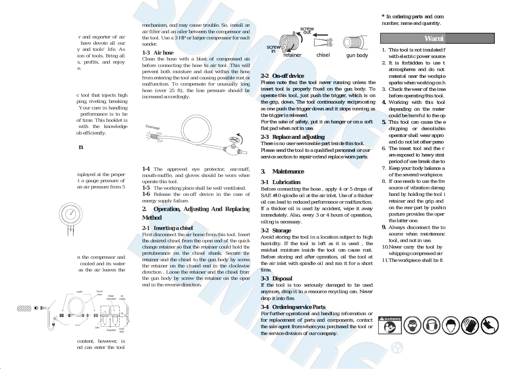
2-1 Inserting a chisel
First disconnect the air horse from this tool. Inser
the desired chisel from the open end of the quic
change retainer so that the retainer could hold th
rotuberance on the chisel shank. Secure th
retainer and the chisel to the gun body by scre
the retainer on the closed end in the clockwis
direction . Loose the retainer and the chisel fro
the gun body by screw the retainer on the ope
end in the reverse direction.
chisel
screw
out
screw
in gun body
retainer
2-2 On-off device
Please note that the tool never running unless the
insert tool is properly fixed on the gun body. To
operate this tool, just push the trigger, which is on
the grip, down. The tool continuously reciprocating
as one push the trigger down and it stops running as
thetriggerisreleased.
For the sake of safety, put it on hanger or on a soft
flat pad when not in use.
2-3 Replace and adjusting
There is no userserviceable part inside this tool.
Please sendthetool to aqualified personnel orour
service section to repair or/and replace worn parts.
3. Maintenance
3-1 Lubrication
Before connecting the hose , apply 4 or 5 drops of
SAE #10 spindle oil at the air inlet. Use of a thicker
oil can lead to reduced performance or malfunction.
If a thicker oil is used by accident, wipe it away
immediately. Also, every 3 or 4 hours of operation,
oilingis necessary.
3-2 Storage
Avoid storing the tool in a location subject to high
humidity. If the tool is left as it is used , the
residual moisture inside the tool can cause rust.
Before storing and after operation, oil the tool at
the air inlet with spindle oil and run it for a short
time.
3-3 Disposal
If the tool is too seriously damaged to be used
anymore, drop it in a resource recycling can. Never
drop it into fire.
3-4 Ordering service Parts
For further operational and handling information or
for replacement of parts and components, contact
the sale agent fromwhom you purchased the tool or
the servicedivision of our company.
*In orderingparts and components, give each part
number, name and quantity.
Warning
1. This tool is not insulated for coming into contact
withelectricpower source.
2. It is forbidden to use this tool in explosive
atmospheres and do not put any combustible
material near the workpiece since it might emit
sparks when working on hard material.
3. Check the wear of the insert tool and the retainer
before operating this tool.
4. Working with this tool will generate dust,
depending on the material being worked on,
could be harmful to the operator
5. This tool can cause the ejection of particles at
chipping or demolishing work, hence the
operator shall wear appropriate protective device
and do not let other person near the work area.
6. The insert tool and the retainer on heavy types
are exposed to heavy strains and can after a long
period of use break due to fatigue.
7. Keep your body balance and beware ofthe break
ofthe severed workpiece.
8. If one needs to use the free hand, although it is a
source of vibration damage, we suggest place the
hand by holding the tool in the part between the
retainer and the grip and do not place the hand
on the rear part by pushing the tool. The former
posture provides the operator more balance than
the latter one.
9. Always disconnect the tool from the air power
source when maintenance, placing any insert
tool, and not in use.
10.
Never carry the tool by hose and beware of a
whippingcompressedairhose.
11.
Theworkpiece shall be fixed by proper device.
ST-24001-I-1906A-FY
Foreword
SUMAKE is a manufacturer and exporter of air
tools since established. We have devote all our
efforts in improving quality and tools’ life. As
well as the noise and vibration of tools. Bring all
of you working efficiences, profits, and enjoy
using the tool is our principle.
Features
This air tool is a pneumatic tool that injects high
efficiency into manual chipping, riveting, breaking
of concrete and asphalt etc. Your care in handling
it is, however, important if performance is to be
realized over a long period of time. This booklet is
prepared to equip you with the knowledge
necessary to keep it on the job efficiently.
Operator‘s instruction
1. Cautions for Use
1-1 Air pressure
Maximum performance is displayed at the proper
sanding speed, obtainable at a gauge pressure of
6.2 bar. Range-wise, this is an air pressure from 5
to 7 bar (70 to 100 psi)
57
1-2 Air line
Use a 3/8“ air hose between the compressor and
the tool . Compressed air is cooled and its water
content separated, as soon as the air leaves the
compressor.
Tool
Nipple
Coupler Recoil
hose
Leader
hose
Oiler Regulator
Water
separation Air
supply
Drain
daily
A portion of the water content, however, is
condensed in the piping, and can enter the tool
mechanism, and may cause trouble. So, install a
air filter and an oiler between the compressor an
the tool. Use a 3 HP or larger compressor for eac
sander.
1-3 Air hose
Clean the hose with a blast of compressed ai
efore connecting the hose to air tool. This wil
revent both moisture and dust within the hos
from entering the tool and causing possible rust o
malfunction. To compensate for unusually lon
hose (over 25 ft), the line pressure should b
increased accordingly.
Drainage
1-4 The approved eye protector, ear-muff
mouth-muffle, and gloves should be worn whe
operate this tool.
1-5 The working place shall be well ventilated.
1-6 Release the on-off device in the case o
energy supply failure.
2. Operation, Adjusting And Replacin
Method
2-1 Inserting a chisel
First disconnect the air horse from this tool. Inser
the desired chisel from the open end of the quic
change retainer so that the retainer could hold th
rotuberance on the chisel shank. Secure th
retainer and the chisel to the gun body by scre
the retainer on the closed end in the clockwis
direction . Loose the retainer and the chisel fro
the gun body by screw the retainer on the ope
end in the reverse direction.
chisel
screw
out
screw
in gun body
retainer
2-2 On-off device
Please note that the tool never running unless the
insert tool is properly fixed on the gun body. To
operate this tool, just push the trigger, which is on
the grip, down. The tool continuously reciprocating
as one push the trigger down and it stops running as
thetriggerisreleased.
For the sake of safety, put it on hanger or on a soft
flat pad when not in use.
2-3 Replace and adjusting
There is no userserviceable part inside this tool.
Please sendthetool to aqualified personnel orour
service section to repair or/and replace worn parts.
3. Maintenance
3-1 Lubrication
Before connecting the hose , apply 4 or 5 drops of
SAE #10 spindle oil at the air inlet. Use of a thicker
oil can lead to reduced performance or malfunction.
If a thicker oil is used by accident, wipe it away
immediately. Also, every 3 or 4 hours of operation,
oilingis necessary.
3-2 Storage
Avoid storing the tool in a location subject to high
humidity. If the tool is left as it is used , the
residual moisture inside the tool can cause rust.
Before storing and after operation, oil the tool at
the air inlet with spindle oil and run it for a short
time.
3-3 Disposal
If the tool is too seriously damaged to be used
anymore, drop it in a resource recycling can. Never
drop it into fire.
3-4 Ordering service Parts
For further operational and handling information or
for replacement of parts and components, contact
the sale agent fromwhom you purchased the tool or
the servicedivision of our company.
*In orderingparts and components, give each part
number, name and quantity.
Warning
1. This tool is not insulated for coming into contact
withelectricpower source.
2. It is forbidden to use this tool in explosive
atmospheres and do not put any combustible
material near the workpiece since it might emit
sparks when working on hard material.
3. Check the wear of the insert tool and the retainer
before operating this tool.
4. Working with this tool will generate dust,
depending on the material being worked on,
could be harmful to the operator
5. This tool can cause the ejection of particles at
chipping or demolishing work, hence the
operator shall wear appropriate protective device
and do not let other person near the work area.
6. The insert tool and the retainer on heavy types
are exposed to heavy strains and can after a long
period of use break due to fatigue.
7. Keep your body balance and beware ofthe break
ofthe severed workpiece.
8. If one needs to use the free hand, although it is a
source of vibration damage, we suggest place the
hand by holding the tool in the part between the
retainer and the grip and do not place the hand
on the rear part by pushing the tool. The former
posture provides the operator more balance than
the latter one.
9. Always disconnect the tool from the air power
source when maintenance, placing any insert
tool, and not in use.
10.
Never carry the tool by hose and beware of a
whippingcompressedairhose.
11.
Theworkpiece shall be fixed by proper device.