manuals.online logo
Brands
  1. Home
  2. •
  3. Brands
  4. •
  5. Sumitomo
  6. •
  7. Industrial Equipment
  8. •
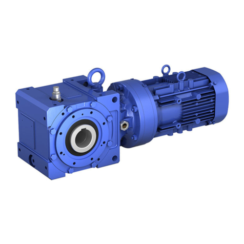
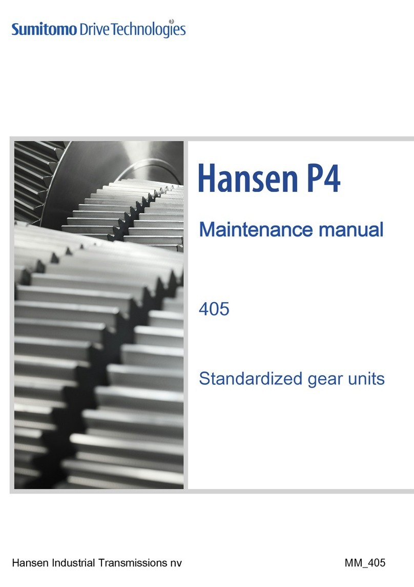
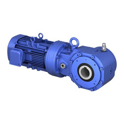
  9. Sumitomo Hansen P4 User manual

Sumitomo Hansen P4 User manual








   



SECTION A - SECTION A - TEIL A - SECCIÓN A
Air cooled condenser drives
Contents A
Commande des ventilateurs des condensateurs à air
Index A10
Antriebsgruppen f r Luftkondensatoren
Inhaltverzeichnis A20
Las transmisiones del ventilador de los condensadores de aire
Índice A30
SECTION B - SECTION B - TEIL B - SECCIÓN B
Cooling tower drives
Contents B
Commande des ventilateurs pour aéroréfrigérants
Index B10
Antriebsgruppen f r K hlt rme
Inhaltverzeichnis B20
Las transmisiones del ventilador para torres de refrigeración
Índice B30
English E
Français F
Deutsch
Español
D
S
Page
E
F
D
S
AIR COOLED CONDENSER DRIVES
Hansen M4 ACC standardized gear units
Programme - Selection
A2
Description
A3 - A4
Selection
A5 - A6
Request for quotation
A - A8
Accessories and options
A39 - A40
Rating tables
Mechanical power ratings and rated thrust load
A41
Exact ratio's i
ex
and moments of inertia J
A41
Thermal power ratings
A42
Dimensional drawings
Hansen M4 ACC gear units without oil filter
A43
Hansen M4 ACC gear units with oil filter
A44
Hansen P4 standardized gear units
Programme - Selection
A2
Description
A45 - A46
Selection
A4 - A48
Request for quotation
A49 - A50
Accessories and options
A69 - A 0
Rating tables
Mechanical power ratings and rated thrust load
A 1
Exact ratio's i
ex
and moments of inertia J
A 1
Thermal power ratings
A 2
Dimensional drawing
Hansen P4 gear units, parallel shafts, two stages
A 3
SECTION A - CONTENTS
E
A
STANDARDISED GEAR UNITS FOR
AIR COOLED CONDENSER DRIVES
PROGRAMME - SELECTION
500
400
355
315
280
250
225
200
160
132
110
90
75
55
45
6,3 7,1 8 9 10 11,2 12,5 14 16 18 20 22,4 25
Nominal ratio
Motor Power
P
m
(kW - 1500 min
-1
) / SF = 1,75
QVP.2 - UDN
C F
DA FX
PVP..2U - UDN
E
I
N
A2
DESCRIPTION
HANSEN M4 ACC GEAR UNITS
FOR AIR COOLED CONDENSER DRIVES
Coding
Type
1 : series P : Hansen M4
2 : V : vertical low speed shaft
3 : P : parallel shafts
4 : Size : DA-> FX
5 : number of stages: 2
Application
6:ACC:Air Cooled Condenser
Shaft arrangement
: high speed shaft extension : U : up
8 : low speed shaft extension : D : down
9 : low speed shaft type : N : normal solid shaft
Ratio
10 : nominal ratio of the gear unit
Drive package
11 : K: lantern drive package
Motor
12 : motor size and number of poles
Units are designed to comply with the standard CTI-111 specifications
for gear units.
The mechanical power ratings shown in the tables relate respectively to
input speeds of 1800, 1500, 1200, 1000, 900 and 50 RPM at the
high speed shaft. They are also valid for asynchronous speeds which
are max. 3% lower than the synchronous speeds.
Interpolation will yield power rating values for intermediate speeds. The
power rating for speeds lower than 50 RPM is based on the
continuous torque rating of that speed.
For input speeds exceeding 1800 RPM, please refer to us.
Basic components
Helical gears
Designed and rated in accordance with AGMA for maximum load
capacity, minimum losses and quiet operation.
All geared components are manufactured from alloy steel, gas
carburized, hardened and precision ground.
Low speed shafts
The low speed shafts are in solid version.
Length of the shaft extension according to customer's specification.
Bearings
Heavy duty roller bearings of the tapered, cylindrical or spherical roller
type.
Calculated in compliance with ISO and renowned bearing
manufacturers.
The low speed shaft bearings are selected to allow considerable thrust
loads. The nominal permissible thrust load F
xN
mentioned in the table,
page A41, is defined for a SFmin = 2, low speed shaft rotating
counter-clockwise and guarantees a calculated bearing life of 100000
hours.
Housings, lantern housings and covers
Made from grey pearlitic cast iron.
Machined on CNC machining centers.
Designed to ensure strength and rigidity.
Unused tapped holes are plugged.
Monobloc housing.
Systems
Lubrication
Lubricants: mineral oils are normally used. Lubricants should always
contain adequate EP-additives (refer to Service Manual).
Pump lubrication for the upper bearings is standard available.
The lubrication is guaranteed for input speeds down to 50 min
-1
(windmilling conditions).
The gear unit housing acts as a large oil sump.
Grease point with nipple according to DIN 1412 for grease lubri-
cation of the bearing at side of the low speed shaft end.
Checking of the oil level is done by means of the gear unit dipstick
(always in the plugged position).
Cooling
Heat generated in the gear unit due to losses, can be dissipated by:
natural cooling through the housing
additional fan cooling, shaft driven axial fan incorpo-
rated in the lantern housing
Free air entry at the suction side should always be
guaranteed
Thermal checks: refer to us.
Fill in "Request for quotation" on page A .
Sealing
Static: generalized use of sealing compound
inspection cover on the gear unit: re-usable flat seal
low speed shaft: drywell
Rotary: high speed shaft: standard : dust lip oil seal
option: regreasable labyrinth
low speed shaft: standard : double dust lip oil seal
option: regreasable labyrinth
The gear unit
1
P
2
V
3
P
4 5
2 U
6
A C C
7
U
8
D
9
N
10
11
K
12
A3
DESCRIPTION
HANSEN M4 ACC GEAR UNITS
FOR AIR COOLED CONDENSER DRIVES
Motors
The gear units are to be fitted with standard flange mounted IEC
motors (type B5). For more information on motors, refer to motor
catalogues.
For Nema motors, refer to us.
Use of two speed motors: when changing speed with two speed
motors, the motor has to be slowed down below the low speed, be-
fore energising the slow speed winding.
Optional devices
Some devices can optionally be provided (refer to pages A39-A40).
More detailed information about the optional devices is mentioned in
separate technical manuals. Refer to us.
Backstop
Built-in backstop to prevent the fan from "windmilling". Internal
lubrication is assured. The backstop is accessible after removing the
motor and the lantern housing.
Filter
With incorporated pressure relief valve.
A filter with incorporated pressure relief valve and visual or electrical
contamination indicator is available as an option.
Heaters
Electrical heating devices for low temperature start-up are available
for Hansen M4 ACC gear units.
Oil level switch
To control the oil level in the gear unit, an oil level switch can be
provided. This switch can trigger an alarm signal when the oil level
falls beneath a specified limit.
Pressure switch or pressure transmitter
To control the oil pressure, a pressure switch or pressure transmitter
can be provided. They can trigger an alarm signal when the oil
pressure falls beneath a specified limit.
Pt100
To control the oil bath temperature. The Pt100 can trigger an alarm
signal when the oil temperature is higher than a specified limit.
Shipping conditions
Inspection prior to shipment
Test run: all gear units are tested under no load
Conformity Check
Protection
Shaft extension: greased and protected with waxed
waterproof paper
Lubricants
Hansen M4 ACC gear units are shipped without oil.
Grease lubrication points are factory filled.
For information relating to storage, handling, installation,
start-up and maintenance, refer to the service manual which is
supplied together with each gear unit.
Protection
Standard protection systems
As a standard, Hansen M4 ACC gear units are provided with a
painting system that is suitable to be applied in the atmospheric-
corrosivity category C4 (L) according to ISO 12944-2 (and ISO
12944-5).
The choice of colour has no influence on the technical quality of the
painting system.
Other painting systems can be offered to meet the required atmos-
pheric-corrosivity category for your application.
Bolts and nuts provided with appropriate protection.
A4
E
SELECTION
Mechanical power rating
AIR COOLED CONDENSER DRIVES
A5
refer to page A
refer to page A2
for ratios < 9 refer to us
Procedure Reference Data
Mechanical power
rating P
Ratio
2
3
for
Ratio
P V P 2U - ACC - U D N
1
SELECTION DATA
Pm , Pa , n
HSS
, n
LSS
, i
N
Thrust load
F
x
PROGRAMME SELECTION
Absorbed Power Pa
P
Motor Power Pm
and
xSF =1
,
5
xSF = 2
PSize
S
E
L
E
C
T
I
O
N
C
H
E
C
K
F
x
: ... kN
Pay attention to direction of F
x
! (Always downwards)
Check if
Size
P
Start-up torque T
S
Check if
T
S
1,5 x
T
T = P x 9,55
n
P: mechanical power rating (kW), see page A41
Mechanical torque of the gear unit (kNm)
n: shaft speed (min
-1
)
F
x
F
xN F
xN
see p. A41
see p. A41
Thermal rating
see pages A6, A42
Total start-up time t
S
For other input speeds (n
1
), following equation can be applied:
t
S
@ n
1
= 1500 x t
S
@ 1500
n
1
Note: make sure that Ts, T and n refer to the same shaft (speed);
Design total start-up time @ 1500 min
-1
refers to the total start-up
time over the design lifetime of the gear unit, taking into account:
- number of start-ups
- duration of a single start-up
- input speed equal to 1500 min
-1
A = T
S
: start-up torque (kNm)
T : mechanical torque rating of the gear unit (kNm)
SELECTION
Thermal power rating
AIR COOLED CONDENSER DRIVES
P
tn
for gear unit
without forced cooling
factor a for ambient temperature without forced cooling
Reduction
Ratio
Ambient temperature in °C
15 to 25 25 to 35 35 to 45
6,3 11,2
12,5 18
Size
1
1
0,81
0,85
1
DA FX
0,8
DA FX
0,68
0, 1
0,55
0,66
0, 5
DA DX
0, 4
EA FX
OK
Thermal check
Pa P
tn
a b c ?
Cooling fan possible
No forced cooling
required
P
tf
for gear unit
with 1 fan
Pa P
tf
d b ? One fan
factor b for duration of service
h/year
3
h/day (max)
10 >16
1000
2000
4000
Size
1,2
-
1,3
-
-
DA DX
-
EA FX
1,15
1,1
1,2
1,1
-
DA DX
-
EA FX
1,15
1,1
1
DA FX
factor d for ambient temperature with forced cooling
Number of
stages
Ambient temperature in °C
15 to 25 25 to 35 35 to 45 45 to 55
with forced
cooling 2 1 0,86 0, 2 0,59
Reference Data
OK
factor c for air circulation (without fan)
Mounting
Indoors
- small enclosure
Air flow
0, 3 0, 0
Indoors
- normal working areas
Outdoors
- protected against sun
Size
1
1,33
DA DX
1
1,36
EA FX
P
t
P
tn
, P
tf
for
see p.
A42
P
t
Ratio
P V P 2U - ACC - U D N
Size
E
A6
Air flow to be selected according to the structure:
Open structure: gear units installed in an open steel frame structure
allowing the cooling tower air flow to pass over the gear unit's housing.
Closed structure: gear units installed on a solid concrete plinth or enclosed
steel frame. This structure prevents the cooling tower air flow from passing
over the gear unit's housing.
REQUEST FOR QUOTATION
AIR COOLED CONDENSER DRIVES
A7
Ref : Date : Name : Si
g
nature :
1. LOAD PARAMETERS
Motor power Pm = kW at min
-1
Absorbed power Pa = kW
Absorbed torque Ta = kNm
Running time in h/day 3
Peak torque in excess of 200% Ta =
Number of starts/stops per 10 hours :
10
.....
>10
%
2. SPEED
High speed shaft (HSS)
Constant speed(s) n1(HSS) = ........ or/and ........ min
-1
Variable speed .......... n1(HSS) ........... min
-1
Direction of rotation: CW
Low speed shaft (LSS)
Constant speed(s) n2 (LSS) = ........ or/and ........ min
-1
Variable speed .......... n2 (LSS) ........... min
-1
Tolerance on speed LSS ± ...... % ± ........... min
-1
Direction of rotation: CCW
3. SHAFT CONFIGURATION :
Parallel shafts
4. THRUST LOAD ON LOW SPEED SHAFT Y N
Weight of fan and coupling
Aerodynamic thrust load away from gear unit
5. INSTALLATION PARAMETERS
=
=
Ambient temperature (°C) near the gear unit :
Structure (see page A6) open
Air speed near the gear unit :
-
kN
kN
min: .....
max: .....
....... m/s
closed
Location
Direct sun exposure
Atmosphere: corrosion category (according to ISO 12944-2): ....
Electric installation
Y
AC
Main power supply
Auxiliary power supply
Protection requirement: ........
3 Ph
N
V Hz
.... ....
.... ....
Insulation: ........
6. NOISE (gear unit + motor)
Max. noise power: dBA
Max. noise pressure:
7. OPTIONAL SPECIFICATIONS
Options to be indicated on pages A39-A40
dBA at ..... m
Motor mount IEC frame: ........
(if not IEC, add dimensional drawing)
Shafts inch
extended shaft end: indicate on sketch of application
Painting (see page A4)
(*) : Durability range according to ISO 12944-1
L : low
M: medium
H: high
Note : the durability range is NOT a "guarantee time".
Durability is a technical consideration that can help
the owner set up a maintenance programme.
(**) : Contains additional layer on 2A, 2B and 2C to avoid chalking.
Not allowable materials Al
Cu
Other
8. BACKSTOP REQUIRED Y
.....
N
9. SHIPMENT
Transport by
vessel
train
truck
Other data available in :
Selection:
tick where
appropriate
2 3
System
Corrosion category according to ISO 12944-2
L
(*)
C1
M H L
C2
M H L
C3
M
2A
2B
3A
(**)
3B
(**)
2C 3C
(**)
Selection:
tick where
appropriate
2 3
System
2A 3A
(**)
2B
2C
3B
(**)
3C
(**)
Corrosion category according to ISO 12944-2
C4
L
(*)
M H L
Not allowed
C5-I
M H
C5-M
L M
Mandatory (minimum requirement)
Upon customer request
H
H
Selection of
corrosion category: tick where appropriate
C1 C2 C3 C4 C5-I C5-M
Sketc of application
TOP VIEW
SIDE VIEW
E
REQUEST FOR QUOTATION
AIR COOLED CONDENSER DRIVES
Ref : Date : Name : Si
g
nature :
A8
COMMANDE DES VENTILATEURS
DES CONDENSATEURS A AIR
Réducteurs standard Hansen M4 ACC
Programme - Sélection
A12
Description
A13 - A14
Sélection
A15 - A16
Demande d'offre
A1 - A18
Accessoires et options
A39 - A40
Tables de sélection
Puissances mécaniques nominales et charge axiale nominale
A41
Rapports de réduction exacts i
ex
et moments d'inertie J
A41
Puissances thermiques nominales
A42
Plans d'encombrement
Réducteurs Hansen M4 ACC sans filtre d'huile
A43
Réducteurs Hansen M4 ACC avec filtre d'huile
A44
Réducteurs standard Hansen P4
Programme - Sélection
A12
Description
A51 - A52
Sélection
A53 - A54
Demande d'offre
A55 - A56
Accessoires et options
A69 - A 0
Tables de sélection
Puissances mécaniques nominales et charge axiale nominale
A 1
Rapports de réduction exacts i
ex
et moments d'inertie J
A 1
Puissances thermiques nominales
A 2
Plan d'encombrement
Réducteurs Hansen P4, arbres parallèles, deux étages
A 3
SECTION A - INDEX
F
A10
REDUCTEURS STANDARD POUR COMMANDE DES
VENTILATEURS DES CONDENSATEURS A AIR
PROGRAMME - SELECTION
500
400
355
315
280
250
225
200
160
132
110
90
75
55
45
6,3 7,1 8 9 10 11,2 12,5 14 16 18 20 22,4 25
Rapport nominal
I
N
Puissance motrice
P
m
(kW - 1500 min
-1
) / SF = 1,75
QVP.2 - UDN
C F
DA FX
PVP..2U - UDN
F
A12
DESCRIPTION
RÉDUCTEURS HANSEN M4 ACC POUR COMMANDE
DES VENTILATEURS DES CONDENSATEURS A AIR
Codification
Type
1 : série P : Hansen M4
2 : V : arbre petite vitesse vertical
3 : P : arbres parallèles
4 : Taille: DA-> FX
5 : nombre de trains d'engrenages: 2
Application
6:ACC:Condensateur à air
Shaft arrangement
: bout d'arbre grande vitesse : U : vers le haut
8 : bout d'arbre petite vitesse: D : vers le bas
9 : type d'arbre petite vitesse: N : arbre plein normal
Rapport de réduction
10 : rapport de réduction nominal du réducteur
Groupe de commande
11 : K: entraînement avec lanterne et moteur
Moteur
12 : taille du moteur et nombre de pôles
Les réducteurs sont conçus conformes aux spécifications standard CTI-
111.
Les puissances mécaniques nominales mentionnées dans les tableaux se
rapportent respectivement à des vitesses d'entrée de 1800, 1500, 1200,
1000, 900 et 50 min
-1
de l'arbre grande vitesse.
Elles sont également valables pour des vitesses asynchrones jusqu'à 3 %
inférieures aux vitesses de synchronisme des moteurs. Pour la puissance à
des vitesses intermédiaires il suffit d'interpoler.
Le couple considéré constant, calculé à 50 min
-1
, servira de base à la
détermination de la puissance pour les vitesses inférieures. Pour des
vitesses d'entrée supérieures à 1800 min
-1
, veuillez nous consulter.
Composants de base
Engrenages hélicoïdaux
Conçus et calculés conformes aux normes AGMA en vigueur pour
obtenir une capacité de charge maximum, des pertes minimales et un
fonctionnement silencieux.
Tous les engrenages sont fabriqués en acier allié, traités par
cémentation, trempés et rectifiés.
Arbres petite vitesse
Les arbres petite vitesse sont disponibles en exécution pleine.
Longueur du bout d'arbre suivant la spécification du client.
Roulements
Roulements de haute capacité à rouleaux cylindriques, coniques ou
sphériques.
Calculés suivant les normes ISO et suivant les spécifications de
fabricants de roulements renommés.
Les roulements de l'arbre petite vitesse sont dimensionnés pour
supporter des charges axiales considérables. Les charges axiales,
nominales admissibles F
xN
mentionnées dans le tableau, pages A41,
sont valables pour un SFmin = 2, un sens de rotation anti-horlogique
de l'arbre petite vitesse et garantissent une durée de vie de 100000
heures.
Carters, paliers et couvercles
Coulés en fonte perlitique grise.
Usinés sur des centres d'usinage à commande numérique.
Conçus en fonction de la résistance et de la rigidité.
Les trous taraudés non utilisés sont fermés par des bouchons.
Carter monobloc.
Systèmes
Lubrification
Lubrifiants : normalement des huiles minérales sont utilisées. Les
lubrifiants doivent toujours comporter des additifs "EP" adéquats (voir
Manuel d'Entretien).
La lubrification par pompe des roulements supérieurs est standard.
La lubrification est garantie pour une vitesse d'entrée supérieure ou
égale à 50 min-1 (conditions d'autorotation).
Le réducteur constitue un réservoir d'huile volumineux.
Les points de graissage à nipple sont conformes à la norme DIN
1412. Le roulement du côté du bout d'arbre petite vitesse est lubrifié
à la graisse.
Le contrôle du niveau d'huile se fait par la jauge d'huile du réducteur
(en position vissée).
Refroidissement
La chaleur produite par les pertes du réducteur, peut être dissipée
par:
refroidissement naturel par le carter
refroidissement supplémentaire par ventilateur axial
incorporé dans la lanterne
L entrée libre de l'air du côté aspiration doit toujours être
garantie
Contrôles thermiques: veuillez nous consulter.
Remplir le formulaire "Demande d'offre" à la page A1 .
Etanchéité
Statique: utilisation généralisée d'une pâte hermétique
couvercle d'inspection au réducteur : joint plat
réutilisable
arbre petite vitesse: buselure à rebord
Dynamique: arbre grande vitesse:
standard: bagues d'étanchéité à
lèvre anti-poussière
option: étanchéité par labyrinthe
regraissable
arbre petite vitesse:
standard : double bagues d'étanchéité à
lèvre anti-poussière
option: étanchéité par labyrinthe
regraissable
Le réducteur
1
P
2
V
3
P
4 5
2 U
6
A C C
7
U
8
D
9
N
10
11
K
12
A13
DESCRIPTION
RÉDUCTEURS HANSEN M4 ACC POUR COMMANDE
DES VENTILATEURS DES CONDENSATEURS A AIR
Moteurs
Les réducteurs à arbres parallèles sont entraînés par des moteurs à
bride CEI (type B5). Pour plus d'information concernant les moteurs,
consultez le catalogue des moteurs.
Pour des moteurs NEMA: veuillez nous consulter.
L emploi de moteurs à 2 vitesses : la commutation des moteurs à 2
vitesses à la vitesse inférieure ne peut se faire qu'après que la vitesse
du moteur soit inférieure à la vitesse minimale.
Dispositifs optionnels
Certains dispositifs peuvent être livrés en option (voir pages A39 -
A40). Des feuilles techniques spécifiques relatives aux dispositifs
optionnels sont disponibles. Veuillez nous consulter.
Antidévireur
Antidévireur incorporé afin d'empêcher que le ventilateur ne tourne
en sens inverse. Lubrification par le bain d'huile. L'antidévireur est
accessible après démontage du moteur et de la lanterne.
Filtre
Avec soupape de surpression incorporée.
Un filtre avec soupape de surpression incorporée et indicateur de
colmatage mécanique ou électrique est disponible en option.
Réchauffeurs
Des réchauffeurs électriques pour démarrage à basse température
sont disponibles pour les réducteurs Hansen M4 ACC.
Interrupteur de niveau d'huile
Afin de contrôler le niveau d'huile dans le réducteur, un interrupteur
de niveau d'huile peut être prévu. Cet interrupteur peut enclencher un
signal d'alarme lorsque le niveau du bain d'huile est inférieur à une
valeur déterminée.
Interrupteur de pression ou transmetteur de pression
Afin de contrôler la pression d'huile, un interrupteur de pression ou
un transmetteur de pression peut être prévu. Cet interrupteur peut
enclencher un signal d'alarme lorsque la pression d'huile est
inférieure à une valeur déterminée.
Pt100
Afin de contrôler la température du bain d'huile, un Pt100 peut être
prévu. Le Pt100 peut enclencher un signal d'alarme lorsque la
température du bain d'huile est supérieure à une valeur déterminée.
Etat des réducteurs à la livraison
Inspection avant expédition
Essai: tous les réducteurs sont soumis à un essai à vide
Contrôle de conformité
Protection
Bouts d'arbre sortants: enduits d'une couche de graisse et
protégés par du papier huilé
Lubrifiants
Les réducteurs Hansen M4 ACC sont livrés sans huile.
Les points de graissage sont garnis de graisse avant livraison.
En ce qui concerne ll
ll''
''ee
eenn
nntt
ttrr
rree
eepp
ppoo
ooss
ssaa
aagg
ggee
ee,,
,, ll
llaa
aa mm
mmaa
aann
nnuu
uutt
ttee
eenn
nntt
ttii
iioo
oonn
nn,,
,, ll
ll''
''ii
iinn
nnss
sstt
ttaa
aall
llll
llaa
aatt
ttii
iioo
oonn
nn,,
,, ll
llaa
aa
mm
mmii
iiss
ssee
ee ee
eenn
nn mm
mmaa
aarr
rrcc
cchh
hhee
ee ee
eett
tt ll
ll''
''ee
eenn
nntt
ttrr
rree
eett
ttii
iiee
eenn
nn, veuillez consulter le Manuel d'Entretien
qui est livré avec chaque réducteur.
Protection
Systèmes de protection standard
En standard, les réducteurs Hansen M4 ACC sont munis d'un
système de peinture qui convient pour être appliqué dans la corro-
sivité atmosphérique catégorie "C4 (L)" suivant ISO 12944-2 (et ISO
12944-5).
Le choix de la couleur n affecte pas la qualité technique du système
de peinture.
D'autres systèmes de peinture peuvent être offerts pour répondre à
la catégorie de corrosivité atmosphérique requise pour votre appli-
cation.
Boulons et écrous: munis d'une protection appropriée.
F
A14
Puissance
mécanique
nominale P
Rapport voir p. A41
SELECTION
Puissance mécanique nominale
COMMANDE DES VENTILATEURS DES CONDENSATEURS A AIR
A15
consulter page A1
consulter page A12
pour rapports < 9 consulter nous
Procédure Données de référence
2
3
pour
Rapport
P V P 2U - ACC - U D N
1
DONNEES DE SELECTION
Pm , Pa , n
HSS
, n
LSS
, i
N
Charge axiale
F
x
SELECTION DU PROGRAMME
Puissance absorbée Pa
P
Puissance motrice Pm
et
xSF =1
,
5
xSF = 2
Taille
S
E
L
E
C
T
I
O
N
V
E
R
I
F
I
E
R
Taille
P
Puissance thermique
voir pages A16, A42
Couple de démarrage T
S
Vérifier si
T
S
1,5 x
T
P
F
x
: ... kN
Vérifier si
F
x
F
xN F
xN
voir p. A41
T = P x 9,55
n
P: puissance mécanique nominale (kw), voir page A41
Couple mécanique nominal du réducteur (kNm)
n: vitesse de sortie (min
-1
)







    




Temps de démarrage total t
S
Pour d autres vitesses d entrée (n
1
), l équation suivante peut être
appliquée:
t
S
@ n
1
= 1500
n
1
x t
S
@ 1500
Remarque: soyez certain que Ts, T et n se rapportent au même arbre
(vitesse);
Temps de démarrage total de conception @ 1500 min
-1
se rapporte
au temps de démarrage total pour la durée de vie de conception du
réducteur, tenat compte de :
- le nombre de démarrages
- la durée d un démarrage
- la vitesse d entrée de 1500 min
-1
A = T
S
: couple de démarrage (kNm)
T : couple mécanique nominal du réducteur (kNm)

Other manuals for Hansen P4

1

This manual suits for next models

1

Other Sumitomo Industrial Equipment manuals

Sumitomo FC-6S+ User manual

Sumitomo

Sumitomo FC-6S+ User manual

Sumitomo Hansen P4 User manual

Sumitomo

Sumitomo Hansen P4 User manual

Sumitomo 82C+ User manual

Sumitomo

Sumitomo 82C+ User manual

Sumitomo PARAMAX 9000 Series User manual

Sumitomo

Sumitomo PARAMAX 9000 Series User manual

Sumitomo TYPE-201e-VS/M4 User manual

Sumitomo

Sumitomo TYPE-201e-VS/M4 User manual

Sumitomo Taper Grip User manual

Sumitomo

Sumitomo Taper Grip User manual

Sumitomo T-57C+ User manual

Sumitomo

Sumitomo T-57C+ User manual

Sumitomo Cyclo BBB4 User manual

Sumitomo

Sumitomo Cyclo BBB4 User manual

Sumitomo BUDDYBOX User manual

Sumitomo

Sumitomo BUDDYBOX User manual

Sumitomo FC-6S+ User manual

Sumitomo

Sumitomo FC-6S+ User manual

Sumitomo TYPE-72M12 User manual

Sumitomo

Sumitomo TYPE-72M12 User manual

Sumitomo Z2C User manual

Sumitomo

Sumitomo Z2C User manual

Sumitomo SRDK Series User manual

Sumitomo

Sumitomo SRDK Series User manual

Sumitomo ASTERO BASA User manual

Sumitomo

Sumitomo ASTERO BASA User manual

Sumitomo TYPE-72C+ User manual

Sumitomo

Sumitomo TYPE-72C+ User manual

Sumitomo Y-OP4-U User manual

Sumitomo

Sumitomo Y-OP4-U User manual

Sumitomo Bevel BUDDYBOX 4 Series User manual

Sumitomo

Sumitomo Bevel BUDDYBOX 4 Series User manual

Sumitomo CC-17 User manual

Sumitomo

Sumitomo CC-17 User manual

Sumitomo TYPE-Q102-M12 User manual

Sumitomo

Sumitomo TYPE-Q102-M12 User manual

Sumitomo FC-6 User manual

Sumitomo

Sumitomo FC-6 User manual

Sumitomo Cyclo BBB5 User manual

Sumitomo

Sumitomo Cyclo BBB5 User manual

Popular Industrial Equipment manuals by other brands

Flex-A-Seal 23M Installation, operation, maintenance guide

Flex-A-Seal

Flex-A-Seal 23M Installation, operation, maintenance guide

Gen Set MG 5000 I-HE owner's manual

Gen Set

Gen Set MG 5000 I-HE owner's manual

Delta DVP-ES2 Operation manual

Delta

Delta DVP-ES2 Operation manual

Ebmpapst W2E200-HK86-01 operating instructions

Ebmpapst

Ebmpapst W2E200-HK86-01 operating instructions

GAMA evolution G-50 H Service manual

GAMA

GAMA evolution G-50 H Service manual

Sherman + Reilly PTR-7230 Operator's manual

Sherman + Reilly

Sherman + Reilly PTR-7230 Operator's manual

Tecnocontrol SE138EO user manual

Tecnocontrol

Tecnocontrol SE138EO user manual

Delta 46-461 instruction manual

Delta

Delta 46-461 instruction manual

System air GEO Installation and operating instructions

System air

System air GEO Installation and operating instructions

woodmizer LT70 Series Safety, Operation, Maintenance & Parts Manual

woodmizer

woodmizer LT70 Series Safety, Operation, Maintenance & Parts Manual

Almaco FLEXICOMPT AUTONOME+ user manual

Almaco

Almaco FLEXICOMPT AUTONOME+ user manual

Unitrol PO-22 instruction manual

Unitrol

Unitrol PO-22 instruction manual

Haufftechnik HRD SG b40 installation instructions

Haufftechnik

Haufftechnik HRD SG b40 installation instructions

woodmizer LT70H AH Safety, Setup, Operation & Maintenance Manual

woodmizer

woodmizer LT70H AH Safety, Setup, Operation & Maintenance Manual

HunterDouglas Luxalon 84B installation instructions

HunterDouglas

HunterDouglas Luxalon 84B installation instructions

Gema UA05-X Operating instructions and spare parts list

Gema

Gema UA05-X Operating instructions and spare parts list

Green&Cool Mistral Operating & maintenance instructions

Green&Cool

Green&Cool Mistral Operating & maintenance instructions

Delta WHITEWATER DF Series Installation, operation and maintenance manual

Delta

Delta WHITEWATER DF Series Installation, operation and maintenance manual

manuals.online logo
manuals.online logoBrands
  • About & Mission
  • Contact us
  • Privacy Policy
  • Terms and Conditions

Copyright 2025 Manuals.Online. All Rights Reserved.