Interpack ETII+ LD User manual
1
HSD2000 ET II
LD
OPERATION MANUAL & PARTS LISTS
2” (48mm) & 3” (72mm)
This Manual Covers Tape Heads with the Serial Numbers Starting with:
H178 or H678
For All Other Numbers, Please Contact Customer Service @ 800-474-827 (Menu #3)
USER MANUAL
ETII+ LD
For Serial Numbers:
H278 and H778 XX X XXX
REV 2 10122022
REV 2 10122022

UH178TW / UH678TW UDH178-01
2
REVISION CONTROL
REVISION CONTROL
REV00 Initial Release
REV01 Updated

UH178TW / UH678TW UDH178-01
3
TABLE OF CONTENTS
Section 1 HHHTUTUTUTable Of ContentsUUUTTTHHH---------------------------------------------------3
Section 2 HHHTUTUTUTechnical AssistanceUUUTTTHHH-----------------------------------------------4
Section 3 HHHTUTUTUWarrantyUUUTTTHHH---------------------------------------------------------------5
Section 4 HHHTUTUTUDescription Of Tape HeadUUUTTTHHH---------------------------------------- 6
Section 5 HHHTUTUTUSafety IssuesUUUTTTHHH--------------------------------------------------------- 7
Section 6 HHHTUTUTUSpecificationsUUUTTTHHH---------------------------------------------------------10
HHHTUTUTUTape Head DimensionsUUUTTTHHH--------------------------------------------10
HHHTUTUTUTape Head ComponentsUUUTTTHHH------------------------------------------ 11
HHHTUTUTUTape Head SpecificationsUUUTTTHHH-----------------------------------------12
Section 7 HHHTUTUTUSet Up ProceduresUUUTTTHHH--------------------------------------------------13
HHHTUTUTUMounting AdaptersUUUTTTHHH--------------------------------------------------14
HHHTUTUTUTape LoadingUUUTTTHHH---------------------------------------------------------15
HHHTUTUTUTape ThreadingUUUTTTHHH------------------------------------------------------16
HHHTUTUTUTape CenteringUUUTTTHHH------------------------------------------------------ 18
HHHTUTUTUTape Leg Length AdjustmentUUUTTTHHH-------------------------------------19
HHHTUTUTUOne Way Clutched Roller AdjustmentUUUTTTHHH------------------------- 20
HHHTUTUTUMain Spring AdjustmentUUUTTTHHH------------------------------------------- 20
HHHTUTUTUMandrel Tension AdjustmentUUUTTTHHH-------------------------------------21
Section 8 HHHTUTUTUTroubleshootingUUUTTTHHH------------------------------------------------------22
Section 9 HHHTUTUTURecommended Spare Parts ListUUUTTTHHH---------------------------------25
Section 10 HHHTUTUTUPreventive MaintenanceUUUTTTHHH-------------------------------------------27
HHHTUTUTUKnife Blade ReplacementUUUTTTHHH----------------------------------------- 27
HHHTUTUTUOiler Pad LubricationUUUTTTHHH----------------------------------------------- 28
HHHTUTUTUUrethane Wipe Down Roller ReplacementUUUTTTHHH------------------- 29
HHHTUTUTUSpring ReplacementsUUUTTTHHH---------------------------------------------- 30
HHHTUTUTUWipe Down Brush ReplacementUUUTTTHHH---------------------------------37
HHHTUTUTUSchedule Of Preventive MaintenanceUUUTTTHHH--------------------------38
Section 11 HHHTUTUTUAppendix A-Illustrations And Parts ListsUUUTTTHHH-----------------------39

UH178TW / UH678TW UDH178-01
4
TECHNICAL ASSISTANCE
Technical Support
This is the Interpack Model HSD 2000-ET II Series LD Tape Head you ordered. It has been
set up and tested in our factory with Intertape brand tapes. If any problems occur when setting
up or operating this equipment, please contact the authorized distributor from where you
purchased this item.
Should you need to contact Interpack Technical Support, please have the Tape
Head UUUmodel number and serial numberUUU available. This information can be found on the
nameplate of the side panel of the tape head. Interpack Technical Support is available during
normal business hours (Eastern Time).
UUUPHONEUUU 1-800-972-4675
If you have a technical question that does not require an immediate response, you may
contact Interpack by fax.
UUUFAXUUU 1-800-462-1293
Replacement Parts
Order parts by UUUitem numberUUU, UUUpart nameUUU and UUUquantity requiredUUU. Replacement parts are
only available from your Authorized Interpack Distributor exclusively.
Should you require assistance selecting the correct part, you may call:
Intertape Polymer Group
Interpack Machinery
9940 Currie Davis Drive, Suite 23B
Tampa, FL, 33619
Tel: 1-800-972-4675
Fax: 1-813-621-8449
MODEL:
SERIAL NUMBER:
DISTRIBUTOR PURCHASED FROM:
DATE OF PURCHASE:

UH178TW / UH678TW UDH178-01
5
WARRANTY
EQUIPMENT WARRANTY AND LIMITED REMEDY: The following warranty is made in lieu of all other
warranties, express or implied, including, but not limited to, the implied warranty of
merchantability, the implied warranty of fitness for a particular purpose, and any implied
warranty arising out of a course of dealing, a custom or usage of trade:
Intertape sells its Interpack Tape Heads, Case Tapers and Case Erectors with the following warranties:
1. The HSDPPP
PPP 2000 Tape Heads' knife blades, springs and wipe down rollers will be free from all
defects for a period of ninety (90) days.
2. All other HSDPPP
PPP 2000 Tape Head parts will be free from all defects for one (1) year after delivery.
3. Water Activated Tapers’ blades and brushes will be free from defects for ninety (90) days after
delivery
4. Drive Belts will be free from defects for ninety (90) days after delivery
5. The Gear Motors will be free from defects for one (1) year after delivery.
6. All other components will be free from defects for one (1) year after delivery.
If any part is proven defective within its warranty period, then the exclusive remedy and
Intertape's and the seller's sole obligation shall be, at Intertype’s option, to repair or replace
the part, provided the defective part is returned immediately to Intertape's factory or an
authorized service station designated by Intertape.
A part will be presumed to have become defective after its warranty period unless the part is
received or Intertape is notified of the problem no later than five (5) calendar days after the
warranty period.
If Intertape is unable to repair or replace the part within a reasonable time, then Intertape, at its
option, will replace the equipment or refund the purchase price. Intertape shall have no
obligation to install the repaired or replacement part.
Intertape shall have no obligation to provide or pay for the labor required to install the repaired
or replacement part. Intertape shall have no obligation to repair or replace (1) those parts
failing due to: operator misuse, carelessness, or due to any accidental cause other than
equipment failure, or (2) parts
1. Failure or damage is due to misapplication, lack of proper maintenance,
abuse, improper installation or abnormal conditions such as temperature,
moisture, dirt or corrosive matter, etc.
2. Failure due to inadequate cleaning, improper operating environment, improper
utilities or operator error.
3. Failure due to operations above the rated capacities, or in any other improper
manner, either intentional or otherwise.
4. Failure is due to equipment, which has been altered by anyone other than an
authorized representative of Intertape Polymer Group.
5. Failure is due to an attempt by the purchaser to correct alleged defective
equipment. In this event the purchaser is responsible for all expenses
incurred.
LIMITATION OF LIABILITY: Intertape and seller shall not be liable for direct, indirect, special,
incidental or consequential damages based upon breach of warranty, breach of contract,
negligence, strict liability or any other legal theory.
The foregoing Equipment Warranty and Limited Remedy and Limitation of Liability may be
changed only by written agreement signed by authorized officers of Intertape and seller.
UH178TW / UH678TW UDH178-01
6
D
ESCRIPTION OF
T
APE
H
EAD
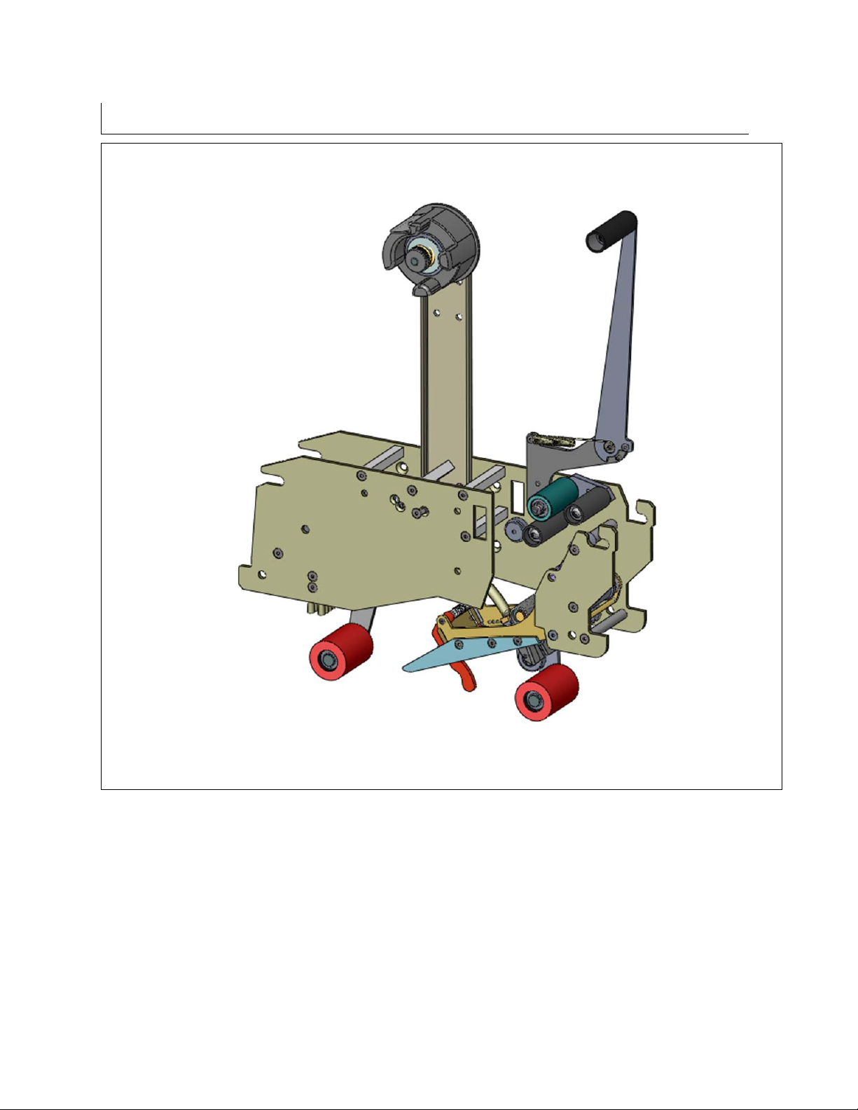
Figure 4-1
The Intertape HSD 2000-ET II Family of Tape Heads are designed to apply Intertape brand
pressure sensitive carton sealing tape to the top and bottom center seam of regular slotted
corrugated cartons.
This HSD 2000-ET II LD is designed to upgrade Little David® case sealers. No adapter kits
are needed to install this tape head into Little David® case sealers.

UH178TW / UH678TW UDH178-01
7
SAFETY ISSUES
There is a safety label used on all Interpack Tape Heads. This label is placed on the Tape
Head knife guard to warn operators and service personnel of the sharp cutting edge of the
blade. Please read the label and the following safety precautions before using the Tape Head.
Read this manual for other important safety operating and service information.
Only trained personnel are to operate and service Tape Head.
Wear safety glasses.
Shut off power to machine before adjusting.
Unplug electrical power before servicing.
All covers and guards must be in place before operating.
Stay clear of moving parts which can shear and cut.
Never operate the Tape Heads with the Knife Guard removed.
Turn electrical supply off before servicing the Tape Heads, including tape
loading and threading.
Note: Should any of the safety labels placed on the Tape Head be
damaged or destroyed, replacements are available.

UH178TW / UH678TW UDH178-01
8
S
AFETY
I
SSUES
The illustrated label shown in Figure 5-1 is
attached to the Knife Guard. The label
warns operators and service personnel of
the very sharp blade. The guard shall only
be removed when the torsion spring or the
guard itself is being replaced.
Should the tape head be operated without
blade guard, user voids all warranty
implied, the manufacturer bears no
responsibility for the consequences.
Tape head shall never be serviced while
mounted in a machine.
Figure 5-1
Label on Figure 5-2 is visible on carton
sealing machine.
Figure 5-2
While the tape head is processing cartons,
or it is in motion, keep your hands away
(Figure 5-3).
Figure 5-3
UH178TW / UH678TW UDH178-01
9
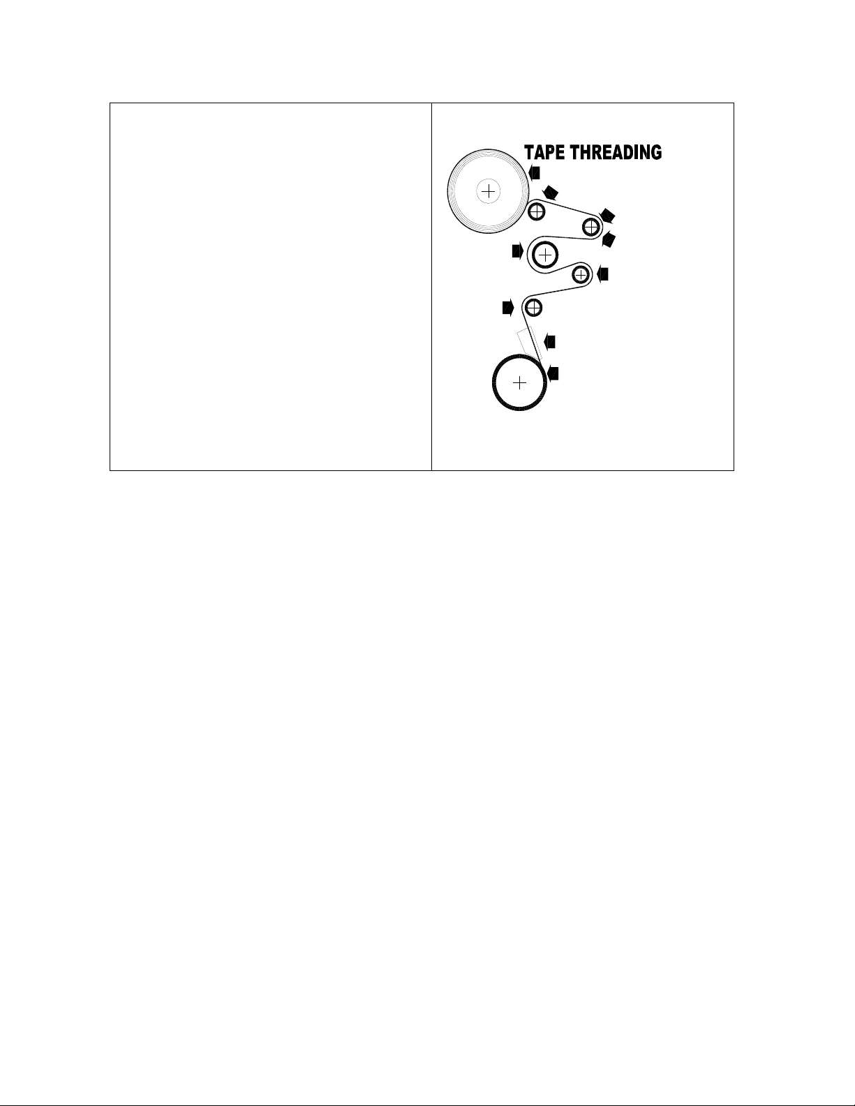
The illustrated label shown in Figure 5-4 is
attached to the operator side plate of each
tape head. The label provides operators
and service personnel the proper method of
threading a new roll of tape through the tape
head.
More detailed information is provided in the
“Set Up Procedures” portion of this manual.
Turn air and electrical supplies off before
servicing the tape heads.
ROLLER
GUIDE
ROLLER
CLUTCH
APPLICATION
TAPE GUIDE
ROLLER
SHOE
GUIDE
ROLLER
ADHESIVE SIDE
TAPE ROLL
GUIDE
ROLLER
PEEL OFF ROLLER
Figure 5-4

UH178TW / UH678TW UDH178-01
10
S
PECIFICATIONS
UUU
Tape Head Dimensions
Figure 6-1

UH178TW / UH678TW UDH178-01
11
S
PECIFICATIONS
UUU
Tape Head Components
Figure 6-2

UH178TW / UH678TW UDH178-01
12
SPECIFICATIONS
UUUOperating Conditions
Use in a dry, relatively clean environment at 40º to 105º F (5º to 40º C) with clean, dry cartons.
Note:
The HSD 2000-ET II LD Tape Head should UUUneverUUU be washed down or subjected to
conditions causing condensation on components. HSD 2000-ET II SS Stainless
Steel tape heads provide protection against mild detergent wash down only. Do
not subject Stainless Steel tape heads to ANY harsh detergent or solvent wash
down. The warrantee will be voided as a result.
UUUTape Head Specifications
1) General
Use Intertape brand Pressure Sensitive Carton Sealing Tape.
2) Tape Width
For HSD 2000-ET II 2” (48mm) models
1 ½ to 2 inch wide tape (36 to 48 mm)
For HSD 2000-ET II 3” (72mm) models
2 ½ to 3 inch wide tape (60 to 72mm)
3) Tape Roll Diameter
Maximum of 16 inches (405 mm) on a 3-inch (76.86 mm) diameter core.
(Accommodates all Intertape brand film tape machine roll lengths)
4) Tape Application Leg Length – Standard
2 ¼ inches (+0.25", -0")
57.15 mm, (+6.3 mm, -0 mm)
5) Tape Application Leg Length – Optional
The tape leg length can be adjusted from:
1 7/8 to 2 3/4 inches
47.8 mm to 69.9 mm
6) Tape Head Weight
The Tape Head weighs 21 lbs. (9.5 kg.) packaged.
7) Operating Speed
For use with line speeds up to 90 ft./min maximum.
UUUPLEASE NOTEUUU: A stronger main spring may be necessary to process cases at
90 ft./ min. Void filled cases should not be processed with the stronger main
spring.

UH178TW / UH678TW UDH178-01
13
SET-UP PROCEDURES
UUUReceiving and Handling
All contents must be verified upon reception. The following items are included with each tape
head.
DESCRIPTION UH 178TW
2” WIDE
PLATED
UH 678TW
3” WIDE
PLATED
Main Tape Head assembly 1 1
Main spring (part no. UPH1090) 1 1
Main spring (part no. UPH0910 1 1
Knife arm spring (part no. UPH4665) 1 1
Operational manual & parts list 1 1
Note: After unpacking the Tape Head, look for any damage that may have
occurred during shipping. Should the Tape Head be damaged, file a claim
with the transport company and notify your Intertape representative.

UH178TW / UH678TW UDH178-01
14
S
ET
-U
P
P
ROCEDURES
WARNING! TURN OFF ELECTRICAL POWER SUPPLY AND DISCONNECT THE POWER CORD
FROM THE ELECTRICAL SUPPLY BEFORE BEGINNING TO WORK ON THE TAPE
HEADS OR TO LOAD TAPE.IF POWER CORDS ARE NOT DISCONNECTED,
SEVERE INJURY TO PERSONNEL COULD RESULT.
UUU
Mounting Adapters
HSD 2000-ET II LD Tape Heads are designed to be installed on Little David® case sealers. If
your Tape Heads are to be installed on a different case sealer or case erector, please review
these general guidelines plus any additional instructions included with your HSD 2000-ET II
LD tape head.
Location Of Mounting Adapter Holes
Front Cover
Figure 7-1
Rear Cover
Figure 7-
2
Examples Of Mounting Hardware
There are numerous mounting holes on the
front and rear side plates of the tape head.
These are used to install various mounting
adaptors. Examples of these mounting
adapters are:
1. Internal and external threaded nuts
2. Mounting Bars
3. Threaded Spacers
Figure 7-3

UH178TW / UH678TW UDH178-01
15
S
ET
-U
P
P
ROCEDURES
UUU
Tape Loading
The HSD 2000-ET II LD Tape Heads accommodate 2-inch (48mm) wide tape rolls, while the
HSD 2000-ET II/3" LD Tape Heads accommodate 3-inch (72mm) wide rolls.
1. Place the tape head onto a sturdy, flat surface.
2. Move the peel off roller away from the mandrel.
3. Push the roll of tape onto the mandrel with the adhesive side up (refer to
Threading Diagram under Tape Threading section in this manual) until the core
seats against the mandrel flange. This ensures the tape will be aligned when
feeding into the tape head.
4. Replace the peel roller against the tape roll.
Figure 7-4
Adhesive Side
Peel Off Roller
Tape Roll
UH178TW / UH678TW UDH178-01
16
SET-UP PROCEDURES
WARNING! THE KNIFE CONTAINED IN THE TAPE HEAD IS EXTREMELY SHARP.USE CAUTION
WHEN REMOVING THE BLADE GUARD AND THREADING THE TAPE TO AVOID
PERSONNEL INJURY.
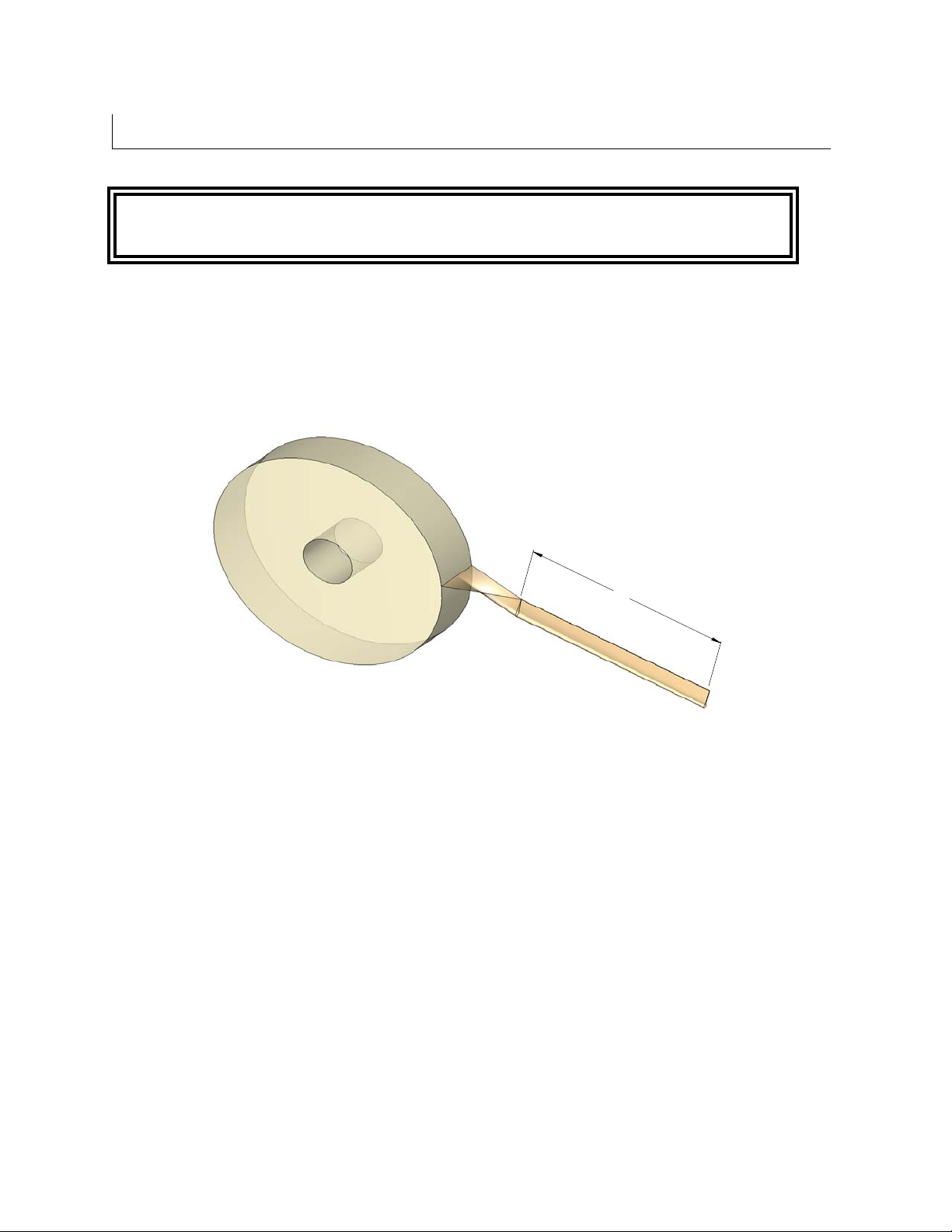
Tape Threading Preparation
Figure 7-5
Threading the tape in the Tape Head does not require any special tools.
1. Pull approximately twelve (12) inches of tape from the roll and fold in half
lengthwise, adhesive side to adhesive side. This allows you to thread the tape
without it adhering to the guide and clutch rollers inside the Tape Head.
12
UH178TW / UH678TW UDH178-01
17
SET-UP PROCEDURES
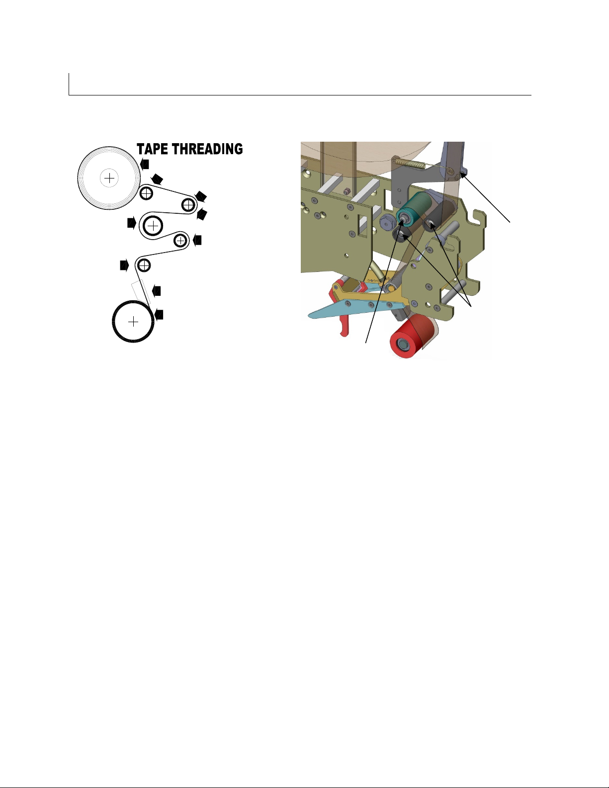
Figure 7-6
Figure 7-7
1. As illustrated in Figures 7-6 & 7-7, first thread the tape tail over the Peel Off
Roller.
2. Thread the tape over and around the first “smooth” Guide Roller.
3. Continue to thread the tape over and around the “knurled” Clutch Roller.
4. Then pass the tape up and over the second “smooth” Guide Roller.
5. Continue threading the tape over and behind the final “knurled” Guide Roller.
6. Thread the tape through the cut-out provided in the Tape Guide Shoe and pull the
tape through the front Application Roller, ensuring that the tape is retained in the
tape guide shoe
7. Cut off the folded tape.
8. Replace the Tape Head to its initial position in the machine.
ROLLER
GUIDE
ROLLER
CLUTCH
APPLICATION
TAPE GUIDE
ROLLER
SHOE
GUIDE
ROLLER
ADHESIVE SIDE
TAPE ROLL
GUIDE
ROLLER
PEEL OFF ROLLER
Adhesive Side
Guide Roller
Clutch Roller

UH178TW / UH678TW UDH178-01
18
SET-UP PROCEDURES
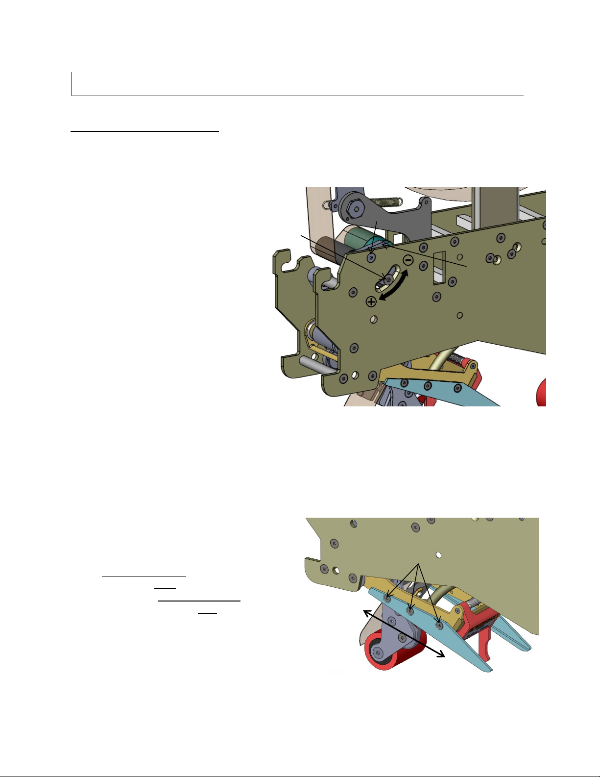
UUUTape Centering
If the tape is not centered as it travels through the tape shoe guide, the tape mandrel can be
adjusted in or out to correct this
Loosen the M18 inverse jam nut on the
rear of the mandrel as shown in Figure
7-8 with a 10 mm Allen key.
Figure 7-8
Adjust the shaft in or out as required
using a flat screwdriver as illustrated in
Figure 7-9. When the tape is
centered, tighten the jam nut .
Figure 7-9
UH178TW / UH678TW UDH178-01
19
SET-UP PROCEDURES
UUUTape Leg Length Adjustment
For optimum performance, the tape leg length has been factory set at 2 inches (50 mm).
However, the tape leg length can be modified.
Front Tape Leg
To adjust the tape leg length on the
leading end of the box, refer to
Figure 7-12 of the clutch assembly.
Facing the rear main frame, loosen
the two (2) Flat Head Cap Screws
using a 3 & 4 mm hexagonal key.
Rotate the clutch assembly to bring
the lowers screw towards the minus
(-) sign stamped on the rear plate for
a shorter tape leg. Conversely, bring
the bottom screw towards the plus
(+) sign for a longer tape leg.
Re-tighten both Flat Head Cap
Screws.
Figure 7-10
Rear Tape Leg
To adjust the tape leg length on the trailing
end of the box, both chrome knife arm
extension brackets must be re-positioned.
Unscrew the three (3) Flat Head Cap
Screws on each knife arm extension using
a 2.5 mm hexagonal key.
For a UUUShorter Tape LegUUU, bring the knife
arm towards the UUUfrontUUU of the tape head.
Conversely, for a UUULonger Tape LegUUU, bring
the knife arm towards the UUUrearUUU of the tape
head.
Replace the three (3) screws on each
knife arm extension and tighten.
Figure 7-11
Front
Rear
M6 M5
CLUTCH
ASSEMBLY
M4
UH178TW / UH678TW UDH178-01
20
SET-UP PROCEDURES
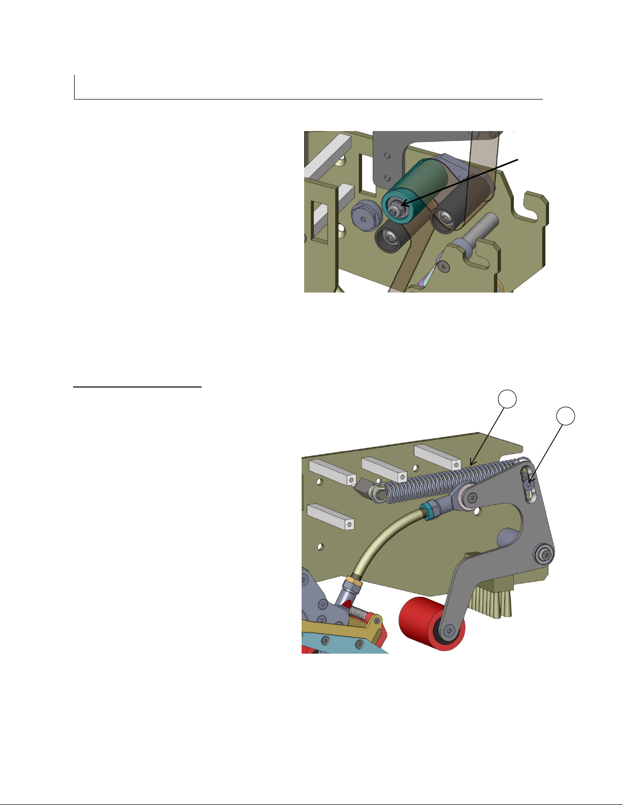
One Way Clutched Roller Adjustment
This one direction, tensionable roller
assures that proper tension is present when
cutting the tape. It is preset at the factory
but should re-adjustment be necessary,
follow these steps:
1. Decrease all mandrel tension
2. Decrease all one way clutched roller
tension
3. Process a case through the
machine. It should not cut tape.
4. Gradually, apply a very small amount
of tension to the one way clutched
roller until a the tape is cleanly cut as
the case processes
5. Too much tension will cause the tape
to wrinkle or snap back
6. Too little tension will not cut the tape.
Figure 7-12
UUUMain Spring Adjustment
The main spring tension is set at the factory.
This setting should be optimal for most
applications. Environments where a
different setting is desirable would be:
1. Void filled cases would need a lighter
wipe down pressure
2. Overfilled cases might require additional
wipe down pressure
3. Double wall corrugated might need
additional wipe down pressure to
overcome the memory of the major flaps.
4. Thinner walled corrugated cases might
require less wipe down pressure
5. Faster line speeds would need additional
spring tension to provide a quicker wipe
down of the rear tape leg.
Should the need arise to increase or
decrease the wipe down pressure, follow
these steps:
1. Remove main spring (Item #1)
2. Loosen the flathead countersink
screw (Item # 2)
3. Relocate to the higher hole to
decrease force or to a lower hole to
increase force.
Figure 7-13
Nylon
Lock
Nut
1 2
Table of contents
Other Interpack Industrial Equipment manuals

Interpack
Interpack RSA 20-B User manual

Interpack
Interpack USA 2024-SB User manual

Interpack
Interpack ipg RSA 2625-TB User manual

Interpack
Interpack HSD2000 XS II Series User manual

Interpack
Interpack CE-12P User manual

Interpack
Interpack CE-12P User manual

Interpack
Interpack HSD2000 ET II RC User manual

Interpack
Interpack USA 2024-SB DH User manual


