manuals.online logo
Brands
  1. Home
  2. •
  3. Brands
  4. •
  5. Summer
  6. •
  7. Indoor Furnishing
  8. •
  9. Summer 07600C User manual

Summer 07600C User manual

Thank you for purchasing the Multi-Use Decorative Extra Tall Walk-Thru Gate from Summer Infant.
This gate allows you to create and maintain a secure environment for your child just about anywhere in
your home. It has a hinged, swinging door that opens easily in either direction with one hand,
as well as hold-open and auto-close features for added convenience.
Multi-Use Decorative Extra Tall
Walk-Thru Gate
INSTRUCTION MANUAL
Please read the following instructions carefully.
Keep this instruction manual and save for future reference.
For technical support, contact us at 1-401-671-6551
or www.summerinfant.com/contact
Tools required: Phillips-head screwdriver,
measuring tape (not included), and wrench (included).
For use with children from 6 - 24 months.
Keep small parts away from children.
Adult assembly required.
Fits openings from 28.5 in. - 48 in. wide.
07600C, 07600CZ, 07600D, 07600DZ, 27410A
Text "Decorative" to 38344 for a demo & install video.
Have questions? We're here to help!
Please contact us at 401-671-6551 or www.summerinfant.com/contact.
components:
WARNING
Children have died or been seriously injured when gates are not securely installed.
• ALWAYS install and use gate as directed using all required parts.
• Install according to manufacturer’s instructions.
• STOP using when a child can climb over or dislodge the gate.
• Use only with the locking/latching mechanism securely engaged.
• To prevent falls, never use at top of stairs without wall mounting cups and door stopper.
• NEVER use a gate to keep child away from pool.
• NEVER leave child unattended.
• Always close and lock the gate behind you.
• This product will not necessarily prevent all accidents. Proper adult supervision is required
at all times.
• Do not use if any components are missing or damaged.
• Adult assembly required. Exercise care when unpacking and assembling product.
CAUTION KEEP SMALL PARTS OUT OF CHILD’S REACH.
Gate Door
Gate Frame
A
B
Long Extension Frame
Short Extension Frames (2)
C
D
Door Stop
Top Latch
E
F
Tension Bolts with Tension Nuts (4)
I
Wall Cups (4)
Adhesive Mounting Pads (4)
J
K
Wall Anchors (4)
L
Lower Latch
Extension Pins (6)
G
H
Screws (4)
M
Wrench
N
hardware:
H
x6 x4
I
2
J K
L M
x4 x4
x4x4
N
x1
A
E
C D
B
F
G
gate configurations (choose which best fits your scenario):
Measure the width of the opening where you intend to install the gate.
• Refer to the following illustrations to determine the correct installation
configuration.
• Baseboard molding may change which configuration is appropriate.
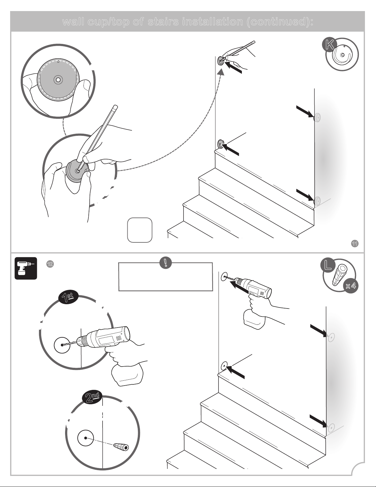
• If mounting the gate at
the top of the stairs,
begin with installation
step #1.
• If mounting the gate in
openings away from
stairs, begin with
installation step #4.
AB
C D
E
(28.5 in.- 32 in.) without extension frames (32.5 in.- 36 in.) with one short extension frame
(36.5 in.- 40 in.) with one long extension frame
(44.5 in.- 48 in.) with both short and the long extension frames
(40.5 in.- 44 in.) with one short and the long extension frames
WARNING
NEVER install three extension
frames on the same side of the
gate.
!
!
Note: This instruction book illustrates installation of gate configuration E.
• If choosing gate configuration A, skip step 4.
• If choosing gate configuration B, add only one short gate extension to either side
of the gate frame in step 4.
• If choosing gate configuration C, add only the large gate extension to either side
of the gate frame in step 4.
• If choosing gate configuration D, add only one short gate extension and the long
extension to either side of the gate frame in step 4.
!
IMPORTANT:
Gate includes a door stop (part F in
components) which prevents the gate
from swinging open in one direction.
• When installing the gate at the top of
stairs, be sure the door stop is on the
stairway side of the gate so the door
cannot open over the stairs.
• While the door stop comes fully
assembled on gate, it can be removed and
installed on either side of gate frame.
• When gate is not used at top of stairs,
door stop may be removed to allow gate
door to open in either direction.
3
4
installation:
5
Connect the
extension frames
to gate frame by
inserting the pins
into the holes
in the gate and
extension frames.
Slide tension bolts
into upper and lower holes
on both sides of
extension frames
(or gate frame if no extensions
are being used).
4
!
• If choosing gate configuration A, skip this step.
• If choosing gate configuration B, add only one short gate extension to either side of the gate frame.
• If choosing gate configuration C, add only the large gate extension to either side of the gate frame.
• If choosing gate configuration D, add only one short gate extension and the long extension to either
side of the gate frame.
x 6
H
x 6
I
x 4
installation (continued):
Check distances A &B.
The distance between the
gate and the wall should
never exceed 2.75"
IMPORTANT
7
6
8
A B
tighten!
tighten!
tighten!
tighten!
!
Make sure door stop is facing desired direction.
For top of stair use, door stop must be on stair
side of gate.
Gate door must open away from stairs.
Use the tension nuts
to tighten both of the
bottom tension bolts.
Use the tension nuts
to tighten both of the
top tension bolts.
Stand the gate in the
center of the opening.
Make sure the bottom of
the gate is completely
flush to the floor.
Slide tension bolts out
until they contact the
door frame or the wall
on both sides.
5
10
9
6
With a pencil, trace
the entire outline
of each tension bolt
directly onto the wall.
STOP! wall cup/top of stairs installation:
WARNING
For use at top of stairs, wall cup
installation is MANDATORY.
Follow these wall cup installation instructions when using gate at TOP OF STAIRS
(MANDATORY), or if using wall cups for a standard opening (optional).
If opting not to use wall cups for a standard opening, skip ahead to step 17.
x 4
Loosen the
lower and upper
tension nuts and
remove gate.
loosen!
loosen!
x 2
x 2
At the top of the
landing, position the
gate a minimum of 3-6
inches (8-15cm) away
from the top step.
IMPORTANT
11
Note: If mounting directly
into wood, skip this step.
!
x 4
Mark drill
holes with a
pencil through
the center
of each wall cup.
Mark drill
holes with a
pencil through
the center
of each wall cup.
x4
Place a wall cup over
the center of each circular
outline on the wall.
Place a wall cup over
the center of each circular
outline on the wall.
wall cup/top of stairs installation (continued):
1
st
Drill a 7/32''pilot hole
into each of the 4
center marks.
Drill a 7/32'' pilot hole
into each of the 4
center marks.
2
nd
Insert wall anchors
into pilot holes.
Insert wall anchors
into pilot holes.
7
12 L
K
Attach one pad to
the back of each
wall cup.
peel
peel
2
nd
3
rd
Remove backing
from one side of each
adhesive mounting pad.
Remove
backing.
1
st
13
Align the wall cups so
the center hole
is placed directly
over the wall anchor.
Stick the wall cups
to the wall.
!
Make sure
all wall cups
are facing up.
Make sure
all wall cups
are facing up.
wall cup/top of stairs installation (continued):
press
press
press
press
14
8
x 4
J
x 4
K
x4
Screw
wall cups
into wall.
x 4
Repeat "installation"
steps on page 5.
The 4 tension bolts
will rest within
each wall cup.
x 4
wall cup/top of stairs installation (continued):
15
16
9
M
NEVER open gate door over stairs.
IMPORTANT
N
wall cup/top of stairs installation (continued):
17
10
Tighten all 4
tension nuts
with the provided
wrench.
x 4
FINISHED!
operation:
to unlock gate: hold-open feature:
Slide locking tab back
to release, lift gate
door open.
testing the installation:
Close the gate.
Make sure the
upper and lower
latches lock
securely.
push!
push!
Push the gate and
extension frames
to check
stability.
1
st
2
nd
11
To activate,
open gate door
at least 90º in
either direction.
Colors and styles may vary.
MADE IN CHINA.
01/28/19
Summer Infant (USA), Inc.
1275 Park East Drive
Woonsocket, RI 02895 USA
1-401-671-6551
© 2019 Summer Infant (USA), Inc.
If the gate does not close properly:
1. Gate is not properly aligned in the door
frame.
Solution: To adjust the gate’s alignment,
loosen all four tension bolts and reposition gate
so that it matches the “correct” image.
Re-tighten tension bolts.
2. Pressure of tension bolts needs to be
adjusted.
Solution: Loosen or tighten the upper tension
bolts. Ensure the upper latch engages securely
when the gate swings closed and that it can be
released properly when the sliding lock tab is
pushed back.
troubleshooting:
maintenance:
• Regularly check tension bolts to make sure the gate is securely in place.
• Do not use the gate if any components are damaged or missing.
• Surface-clean with a damp cloth or sponge, using mild detergent and warm water.
• To order a hardware replacement kit (item #07600-10), contact our Consumer Relations Team
online or by phone at 1-401-671-6551.
correct!
Make sure
upper latch
handle remains
below release
button!
incorrect!
We're here to help!
If you have any questions or need assistance,
contact our Consumer Relations Team at
1-401-671-6551 or www.summerinfant.com/contact

This manual suits for next models

4

Other Summer Indoor Furnishing manuals

Summer 07600A User manual

Summer

Summer 07600A User manual

Summer Sure and Secure 07030 User manual

Summer

Summer Sure and Secure 07030 User manual

Summer Extra Tall & Wide Arch User manual

Summer

Summer Extra Tall & Wide Arch User manual

Summer West End 27950 User manual

Summer

Summer West End 27950 User manual

Summer 27903Z User manual

Summer

Summer 27903Z User manual

Summer Sure & Secure 12494 User manual

Summer

Summer Sure & Secure 12494 User manual

Summer 27256A User manual

Summer

Summer 27256A User manual

Summer SURE AND SECURE 27681 User manual

Summer

Summer SURE AND SECURE 27681 User manual

Summer 27730A User manual

Summer

Summer 27730A User manual

Summer 27990 User manual

Summer

Summer 27990 User manual

Summer Central Station User manual

Summer

Summer Central Station User manual

Popular Indoor Furnishing manuals by other brands

Rauch 58160.3480 Assembly instructions

Rauch

Rauch 58160.3480 Assembly instructions

Furinno 99940 Assembly instruction

Furinno

Furinno 99940 Assembly instruction

Broyhill GB22-812 Assembly instructions

Broyhill

Broyhill GB22-812 Assembly instructions

Furinno 16050 Assembly instruction

Furinno

Furinno 16050 Assembly instruction

Dorel Ameriwood Industries 3597319PCOM manual

Dorel

Dorel Ameriwood Industries 3597319PCOM manual

DITALIA CD-161 Assembly manual

DITALIA

DITALIA CD-161 Assembly manual

modway MOD-6333 Assembly instruction

modway

modway MOD-6333 Assembly instruction

Cooper Lighting 618 Series Specification sheet

Cooper Lighting

Cooper Lighting 618 Series Specification sheet

Woodendot Alba Headboard Assembly instructions

Woodendot

Woodendot Alba Headboard Assembly instructions

Winners Only DQT13678 Assembly instructions

Winners Only

Winners Only DQT13678 Assembly instructions

Coaster Leona 721868 Assembly instructions

Coaster

Coaster Leona 721868 Assembly instructions

physa OTLEY BLACK user manual

physa

physa OTLEY BLACK user manual

Mocka Claremont Entertainment Unit Assembly instructions

Mocka

Mocka Claremont Entertainment Unit Assembly instructions

Coaster 736178 Assembly instructions

Coaster

Coaster 736178 Assembly instructions

Winners Only GE154R Assembly instructions

Winners Only

Winners Only GE154R Assembly instructions

PATIO TIME DB135 instruction manual

PATIO TIME

PATIO TIME DB135 instruction manual

Steve Silver DL250CBN Assembly instructions

Steve Silver

Steve Silver DL250CBN Assembly instructions

CASARIA 109599 instructions

CASARIA

CASARIA 109599 instructions

manuals.online logo
manuals.online logoBrands
  • About & Mission
  • Contact us
  • Privacy Policy
  • Terms and Conditions

Copyright 2025 Manuals.Online. All Rights Reserved.