manuals.online logo
Brands
  1. Home
  2. •
  3. Brands
  4. •
  5. Summers
  6. •
  7. Farm Equipment
  8. •
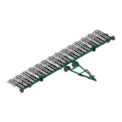
  9. Summers DT9530 User manual

Summers DT9530 User manual

®
Operator’s
Manual
DT9530 &
DK9630
DISK MODELS
SUMMERS MANUFACTURING CO., INC.
WEB SITE: www.summersmfg.com
DEVILS LAKE, NORTH DAKOTA 58301 (701) 662-5391
8Z1091 © Summers Mfg. Co., Inc. 2018 Printed in USA
IMPORTANT
THE OPERATOR IS RESPONSIBLE
FOR ADJUSTING THE MACHINE SINCE
MACHINE DOES NOT COME “FIELD
READY” FROM FACTORY.
CAUTION
READ & UNDERSTAND OPERATOR’S
MANUAL BEFORE USING MACHINE.
DIAMOND DISK & DT9530
See www.summersmfg.com for latest version of all Summers Operator’s Manuals.
Warranty
Summers warrants only products of its manufacture against operational failure caused by defective materials
or workmanship which occur during normal use within 36 months from the date of purchase by the end user from
Summers’ dealer.
Summers’ obligation is to replace free of charge any part of any product that Summers inspection shows to be
defective excluding transportation charges to Devils Lake, ND and return and also excluding all transportation costs
from Summers’ dealer to the dealer’s customer and all other costs such as removal and installation expense.
Summers shall not be liable for loss of time, manufacturing costs, labor, material, loss of prots, consequential
damages, direct or indirect, because of defective products whether due to rights arising under the contract of sale or
independently thereof, and whether or not such claim is based on contract, tort or warranty.
Written permission for any warranty claim return must be rst obtained from authorized Summers’ personnel.
All returns must be accompanied with a complete written explanation of claimed defects and the circumstances of
operational failure.
Written warranty for all component parts used in the manufacture of Summers products is available upon request.
Warranty of such component parts will be determined by said component manufacturer upon their inspection of the
claimed defective part.
This express warranty is the sole warranty of Summers. There are no warranties, which extend beyond the war-
ranty herein expressly set forth. The sales for products of Summers under any other warranty or guarantee express
or implied is not authorized. This warranty voids all previous issues.
SUMMERS MANUFACTURING CO. INC.
DEVILS LAKE, NORTH DAKOTA 58301
01/16
Publish Date: 8/27/2018
(located by the hitch piece)
GENERAL INFORMATION
This book is composed of four basic sections: Safety, Assembly, Operation and Maintenance, and Parts. The As-
sembly Section provides complete instructions for the proper assembly of your Summers DIAMOND DISK &
DT9530. The Operation Section provides information for the proper operation and maintenance of your Summers
DIAMOND DISK & DT9530. A complete parts breakdown is provided in the Parts Section.
Parts are referenced in each drawing with the Summers Manufacturing Part Number. Use this Part Number when ordering
replacement parts from your Summers dealer. See back section of manual for description of each Part Number.
Reference to “Right” and “Left” in this book is determined when the machine is viewed from the rear.
It is the policy of this company to improve its products whenever possible and practical to do so. We reserve the right to
make changes or improvements in the design or construction of parts at any time without incurring the obligation to install
such changes on products previously delivered.
Summers Manufacturing Company, Inc. strongly recommends that each DIAMOND DISK & DT9530 Operator
READ and UNDERSTAND the Operator’s Manual before using the machine. In addition, this Operator’s Manual
should be REVIEWED at least ANNUALLY thereafter.
Scan code to the right for the latest version of all Summers Operator’s Manuals.
SECTION CONTENTS
Section 1: SAFETY
Section 2: ASSEMBLY INSTRUCTIONS
Section 3: OPERATION, MAINTENANCE AND SPECIFICATIONS
Section 4: PARTS
Section 5: PART NUMBERS & DESCRIPTIONS
OWNER REGISTER
Name ________________________________ Size _____________________________________
Address ______________________________ Serial Number _____________________________
City __________________________________
State/Prov. ____________________________ Date Purchased____________________________
Mail Code _____________________________ Dealer ___________________________________
i
TABLE OF CONTENTS
SECTION 1 - SAFETY
Safety-Alert Symbol & General Safety Practices................................................................................................. 1-1
Safety Decals ..............................................................................................................................................1-2 - 1-8
SECTION 2 - ASSEMBLY
General Assembly Safety Practices .................................................................................................................... 2-1
General Assembly - All Units ...................................................................................................................... 2-2 – 2-3
16’ Units.................................................................................................................................................... 2-4 – 2-10
21’ Units.................................................................................................................................................. 2-11 – 2-19
25’-28.5’ Units......................................................................................................................................... 2-20 – 2-28
SECTION 3 - OPERATION & MAINTENANCE
Start-Up ............................................................................................................................................................... 3-1
Hydraulic Operation and Maintenance ................................................................................................................ 3-1
Field Operation .......................................................................................................................................... 3-2 – 3-3
Storage, Troubleshooting and Dimensions................................................................................................. 3-4 – 3-5
Bolt Torque Specications ................................................................................................................................... 3-6
SECTION 4 - PARTS
Depth Control Hydraulics............................................................................................................................ 4-1 – 4-2
Main Frame ........................................................................................................................................................ 4-3
25’ - 28.5’ Wing.................................................................................................................................................... 4-4
21’ Hydraulics Wing Lift ...................................................................................................................................... 4-5
25’ - 28.5 Hydraulics Wing Lift ............................................................................................................................ 4-6
Hydraulic Rear Coulter ........................................................................................................................................ 4-7
Gang Layouts ......................................................................................................................................... 4-8 -– 4-11
Rear Coulter Gang ................................................................................................................................. 4-12 – 4-13
Gang Components ............................................................................................................................................ 4-14
Mounted Rolling Basket.......................................................................................................................... 4-15 – 4-18
Mounted Harrow..................................................................................................................................... 4-19 – 4-22
8K9250 Wing Weight Package.......................................................................................................................... 4-23
Light Kit ............................................................................................................................................................. 4-24
Hub and Axle Components ............................................................................................................................... 4-25
Mounted Attachment Components ........................................................................................................ 4-26 – 4-28
8K1850 - Acre Meter.......................................................................................................................................... 4-29
SECTION 5 - PART NUMBERS & DESCRIPTIONS ................................................................................ 5-1 – 5-3
ii
SECTION 1 - SAFETY
1-1
SAFETY-ALERT SYMBOL
This symbol is used to denote possible danger and
care should be taken to prevent bodily injury.
This symbol means:
ATTENTION! BECOME ALERT!
YOUR SAFETY IS INVOLVED!
Denition of each Signal Word used in conjunction with the Safety-Alert symbol.
indicates an imminently hazardous situation which, if not avoided, will result in death or
serious injury. This signal word is to limited to the most extreme situations.
indicates a potentially hazardous situation which, if not avoided, could result in death or
serious injury.
indicates a potentially hazardous situation which, if not avoided, may result in minor
or moderate injury. It may also be used to alert against unsafe practices.
GENERAL SAFETY PRACTICES
1. READ AND UNDERSTAND Operator’s Manual before using machine. Review at least annually thereafter.
2. VERIFY all safety devices and shields are in place before using machine.
3. KEEP hands, feet, hair and clothing away from moving parts.
4. STOP engine, place all controls in neutral, set parking brake, remove ignition key and wait for all mov-
ing parts to stop before servicing, adjusting or maintaining.
5. BE CAREFUL when working around high pressure hydraulic system.
6. DO NOT ALLOW RIDERS.
SAFETY DURING TRANSPORT
1. ONLY TOW at a safe speed. Use caution when making corners and meeting trafc.
2. USE safety chain between tractor drawbar and implement hitch when transporting on public roads.
3. ALWAYS use transport locks when transporting on public roads.
4. COMPLY with local lighting, marking and oversize regulations when transporting on highways.
5. FREQUENTLY check for trafc from rear, especially during turns.
DANGER
WARNING
CAUTION
WARNING
REMOVE TRANSPORT LOCK(S) BEFORE LOWERING MACHINE.
IF LOCK(S) DO NOT REMOVE FREELY, INSURE THAT
CYLINDERS ARE COMPLETELY FILLED WITH HYDRAULIC
FLUID AND ARE SUPPORTING THE LOAD TO BE LOWERED.
8Z0075
CAUTION
1. Read and understand Operator’s Manual before using machine.
2. For Sprayers:
a. Read and follow chemical manufacturers’ WARNINGS, instructions and procedures before
using.
b. Use recommended personal protective equipment to reduce or eliminate chemical contact.
c. Never run pump dry.
3. Verify all safety devices and shields are in place before using machine.
4. Keep hands, feet, hair and clothing away from moving parts.
5. Stop engine, place all controls in neutral, set parking brakes, remove ignition key and wait for
all moving parts to stop before servicing, adjusting, maintaining or unplugging.
6. Be careful when working around high pressure hydraulic system.
7. Do not allow riders.
8. Check all wheel bolts DAILY for tightness.
9. Refer to Operator’s Manual for periodic and annual maintenance.
10. For Towed Implements, DO NOT EXCEED 20 MPH.
8Z0276
IMPORTANT
TO REPHASE CYLINDERS, RAISE
MACHINE AND MAINTAIN HYDRAULIC
PRESSURE TEN SECONDS AFTER
CYLINDERS ARE FULLY EXTENDED.
QUICKLY RETRACT CYLINDERS AT
LEAST 1/2”. REPHASING SHOULD BE
DONE EVERY HOUR OF OPERATION TO
MAINTAIN UNIFORM TILLAGE DEPTH.
8Z0340
SECTION 1 - SAFETY
1-2
SAFETY DECALS
A. KEEP SAFETY DECALS CLEAN.
B. REPLACE missing or unreadable decals. New decals are available from your Summers dealer by ordering
correct part number (PN) located on decal.
C. Locations shown on Page 1-6.
1. TRANSPORT LOCK WARNING DECAL (PN 8Z0075)
2. GENERAL CAUTION DECAL (PN 8Z0276)
3. REPHASING CYLINDERS DECAL (PN 8Z0340)
WARNING
TO AVOID INJURY
INSTALL CYLINDER
LOCKS BEFORE
TRANSPORTING OR
SERVICING MACHINE. 8Z0342
TO AVOID INJURY OR DEATH
STAND CLEAR OF MACHINE
WHEN WINGS ARE BEING
RAISED AND LOWERED.
MECHANICAL OR HYDRAU-
LIC FAILURE CAN ALLOW
WINGS TO FALL RAPIDLY.
8Z0344
DANGER
8Z0346
TO AVOID INJURY OR DEATH
DO NOT CONTACT
ELECTRICAL LINES.
DANGER
SECTION 1 - SAFETY
1-3
4. INSTALLING CYLINDER LOCKS DECAL (PN 8Z0342)
5. STAYING CLEAR OF WINGS DECAL (PN 8Z0344)
6. ELECTROCUTION DANGER DECAL (PN 8Z0346)
FRAME PINCH POINT HAZARD
KEEP AWAY
To prevent serious injury or death from crushing:
• Stay away from frame hinge area when folding
wings.
• Keep others away.
• Do not fold wings when bystanders are present.
DANGER
8Z0087
IMPORTANT
*GREASE GANG BEARINGS EVERY 20 HOURS.*
GREASE AT MID DAY OR END OF DAY WHEN
BEARINGS ARE AT OPERATING TEMPERATURE.
ADD 3 STROKES OF CHEVRON ULTRA-DUTY EP
NLGI 2 OR EQUIVALENT. ROTATE GANG 2 TO 3
REVOLUTIONS. ADD THREE MORE STROKES.
GREASE ALL ZERKS ON MACHINE BEFORE
EXTENDED STORAGE PERIOD. 8Z0350
®
SECTION 1 - SAFETY
1-4
7. PINCH POINT DECAL (PN 8Z0087)
8. SUMMERS DECAL (8Z0204)
9. GANG BEARING GREASE (PN 8Z0350)
10. AMBER REFLECTOR (PN 8Z0800)
SECTION 1 - SAFETY
1-5
11. RED-ORANGE REFLECTOR (PN 8Z0805)
12. RED REFLECTOR (PN 8Z0810)
13. DK9630 DECAL (8Z2255)
13. DT9530 DECAL (8Z2290)
SAFETY LIGHT OPERATION
The Summers Safety Light Kit is equipped with a 7 pin connector. To protect 7 pin connector, store
in dust cap (8K8067) when not attached to towing vehicle.
9/3/2013 DECAL LOCATIONS.iam
B
8Z0204
5.5" SUMMERS DECAL
8Z2290
DT9530 DECAL
8Z0202T
3.5" SUMMERS DECAL
8Z0344
8Z0075
8Z0344
8Z0100
FEMA DECAL
(NO PN)
8Z0276
8Z0055
SERIAL PLATE
8Z0346
8Z0087
8Z0800
8Z0805
8Z0810
8Z0344
8Z2290
DT9530 DECAL
SECTION 1 - SAFETY
1-6
SECTION 1 - SAFETY
1-7
Front Left Caster
Rear Lights
Rear Center
Rear
SECTION 1 - SAFETY
1-8
Front
Rear Coulter Gang Hyd. Valve
Side View
Rear View
SECTION 2 - ASSEMBLY
2-1
YOU ARE RESPONSIBLE
for the safe assembly of the
machine.
DO NOT ALLOW CHILDREN
or other unauthorized persons
within the assembly area.
WEAR PERSONAL
PROTECTIVE EQUIPMENT
which includes a hard hat,
eye protection, work gloves
and steel toed boots with slip
resistant soles.
DO NOT MODIFY the equipment
or substitute parts in any way.
Unauthorized modication may
impair the function and/or safety
of the machine.
USE SUITABLE LIFTING
DEVICE for components which
could cause personal injury.
BLOCK UP ANY RAISED PART
of the machine. Be sure machine
is stable after blocking.
ALWAYS INSPECT LIFTING
CHAINS AND SLINGS for
damage or wear.
BE SURE LIFTING DEVICE
IS RATED TO HANDLE THE
WEIGHT.
STOP ENGINE, place all
controls in neutral, set parking
brakes, remove ignition key and
wait for all moving parts to stop
before servicing or adjusting.
BE SURE PRESSURE IS
RELIEVED from hydraulic
circuits before servicing or
disconnecting from tractor.
USE EXTREME CARE when
assembling, servicing or
adjusting.
GENERAL ASSEMBLY SAFETY PRACTICES
SECTION 2 - ASSEMBLY
2-2
ASSEMBLY INSTRUCTIONS FOR 16 FT. - 28.5 FT.
Refer to illustrations and follow these steps when assembling.
The machine should be placed in an area that allows ample room for assembly in the eld position.
CAUTION: For safety purposes, always block equipment while working on it.
MAIN FRAME:
Refer to pages 2-4 thru 2-28 and Parts Section when assembling main frame.
Place left and right center frames on stable supports approximately 3 feet off oor. Bolt center frames together using
front splice tube and rear cross tube.
LIFT ARMS
Install lift arm assemblies on center and wings using 1-1/2” dia. x 15-1/2” pins and secure with 7/16” x 3-1/2” bolts and
locknuts.
WALKING TANDEM ASSEMBLIES (Rear Center Only)
Check inside surface of walking tandem assemblies (8T4132). A 3-3/4” diameter surface around the 1-1/2” dia. pivot hole
must be smooth and burr-free. Remove any welding spatter or roughness prior to further assembly. Install snap rings
(8K1920) past grooves of lower pivot tube on the rear center lift arm assemblies. Install V-seal over lower pivot tubes
until solid side is against snap ring. Protect lip of V-seal during assembly.
Install walking tandem assemblies to the bottom of rear center liftarms. Mount so axle closest to the center of machine
is towards rear. Insert pivot pin (8T3620) through walking tandem assembly and lift arm. Retain with 7/16” x 3-1/2” bolts
and locknuts. Push V-seal against walking tandem assembly and secure by placing snap ring into groove.
WHEELS
Insert axle and hub assemblies. Apply good quality anti-seize to axles before inserting into receiver tubes. Retain with
1/2 x 3-3/4” bolts and locknuts in outside position. Install wheel and tire assemblies, retain with 5/8” wheel nuts (torque
required: 240 ft-lbs).
A-FRAMES
Mount A-Frame assemblies above lift arm assemblies as shown.
Install the adjustable cylinder bolts next. Set nuts so bolts are in the middle of the adjustment. Insure that cylinder attach
holes are aligned when eye bolts are tightened. These will be readjusted later.
WING LOCKS
Install Locks on rear cross tube, slide as far away from center as possible, tighten hardware.
MAIN LIFT HYDRAULIC SYSTEM
Refer to page 4-1 or 4-2 when assembling the main lift hydraulic system.
Attach cylinders to adjustment bolts and lift arms as shown. Note the different sized cylinders. Cylinders must be in their
proper location. Install all ttings into cylinders. Route hoses as shown. Use clamps provided to secure hoses to frame.
Tighten hose hold-down clamps enough to retain hoses but loose enough that clamps can be turned by hand. Hydraulic
hoses will expand and shorten when pressurized. Tighten all ttings.
IMPORTANT: Allow enough hose at hinge points to avoid pinching or stretching the hose.
SECTION 2 - ASSEMBLY
2-3
WING LIFT HYDRAULIC SYSTEM
Refer to page 4-5 or 4-6 when assembling the wing lift system. Mount lift cylinders to adjustment bolts and route hoses
as shown. NOTE: CYLINDER PORTS MUST BE FACING DOWN. Fill lift cylinders with oil before attaching lift linkage.
Position adjustment bolts by starting end nuts so they are ush with bolt. Once lift cylinders have been lled with oil and
cycle smoothly, connect wing lift linkage. Adjust eye bolts after gangs have been mounted.
CAUTION: Stand clear whenever raising or lowering wings.
HITCH
Attach hitch using (2) 1-1/2” dia. x 10-5/8” pins and secure with 7/16” x 3-1/2” bolts and locknuts.
GANG MOUNTING
Refer to gang layout on page 4-8 through 4-11.
On Diamond Disk position gangs so notched blades are located at rear center of disk.
Start from the center and work towards the outside when hanging gangs. Lift gang up to the frame close to the correct
location.Secure with 7/8” x 3” bolts, lock washers and locknuts.
MOUNTING WEIGHT PACKAGE
Mount weight packages on outside of wings in location that will not interfere with disk gang or tire travel. Install 1/2 weight
packages (6 suitcase weights with mounting angles and hardware) by positioning mounting angles 8-1/2” apart. Secure
with 3/4” U-bolts, lockwashers and nuts. Fully tighten hardware on one mounting angle. Hand tighten mounting hardware
on second mounting angle, this must be free to slide. Insert one 1” x 10-1/2” bolt through both mounting angles, turn 1”
nut onto this bolt until threads are ush with outside of nut. Spread mounting angles as much as 1” bolt and nut will allow.
Lift suitcase weights (8K9230) into position, slide slotted hole of weight over 1” bolt. Continue to slide weight past corner
of slot until it reaches the end of the slot, at this location the hole without slot will line up with the second hole in the
mounting angles. Repeat procedure with remaining suitcase weights. Insert second 1” x 10-1/2” bolt through angles
and weights. Secure second 1” bolt with lockwasher and nut, fully tighten. When second 1” bolt is tight, remove the nut
from rst bolt and add the lockwasher. Fully tighten all remaining nuts.
Caution: Each suitcase weight (8K9230) weighs 70#, use extreme care when handling them.
SAFETY
Install SMV mounting bracket at machine center. Install remaining decals at locations shown on page 1-6. Install Safety
Light Kit, refer to breakdown on page 4-24.
MOUNT REAR ATTACHMENT (OPTIONAL)
See Page 4-15 or 4-22.
FRAME PKG 16' N-DSK3/10/2015 8K3516.iam/
37
13
128
119 119
128
106 95
51
124
125
121
129
3
154
58
34
118 117
96 97
104
103
71
19
103
50
117
94
41
109
121 129
40
35
38
109
109
129
121
39
52
53
104
59
113
88
137
137 88
113
SECTION 2 - ASSEMBLY
2-4
FRAME PKG 16' N-DSK3/10/2015 8K3516.iam/
59
58
34
104
123
131
12
47 48
118 74
72
72
74
1
120
55 2
107
100
133
126
113
134
136
117
98
96
103
108
44
111 19
71
93
45 124
125
122
130
110
128 119
11
10
92
29
29
51
43
46
43
42
SECTION 2 - ASSEMBLY
2-5
FRAME PKG 16' N-DSK3/10/2015 8K3516.iam/
14
112
18
130
122
116
64
16
132
105
17
136
54
36
49
117
103
99
SECTION 2 - ASSEMBLY
2-6
DETAIL B
SCALE 1 / 16
DETAIL C
SCALE 1 / 16
DETAIL D
SCALE 1 / 16
B
C
D
FRAME PKG 16' N-DSK3/10/2015 8K3516.iam/
114
62
266
265
67 68 5
259
261
254
257
85
87
86 70 115
5
102
114
255
264
255
264 253
256
66
64
99
263
63
115
62
67
73
61
114
60
115
4
73
67
70
70
67
SECTION 2 - ASSEMBLY
2-7
FRAME PKG 16' N-DSK3/10/2015 8T1060.iam/
DEPTH CONTROL HYDRAULICS
TO 94
TO TRACTOR
95
TOP VIEW
29
30
24
29
24 23
15
90
21
95
94
92
93
79 82
78
80
83
91
89
SECTION 2 - ASSEMBLY
2-8

This manual suits for next models

1

Other Summers Farm Equipment manuals

Summers SW4350 User manual

Summers

Summers SW4350 User manual

Summers SFX1630 User manual

Summers

Summers SFX1630 User manual

Summers VRT Renegade User manual

Summers

Summers VRT Renegade User manual

Summers RP6700 User manual

Summers

Summers RP6700 User manual

Popular Farm Equipment manuals by other brands

Unverferth Killbros SeedVeyor 102 manual

Unverferth

Unverferth Killbros SeedVeyor 102 manual

Buhler 480 Assembly instructions

Buhler

Buhler 480 Assembly instructions

Chore-Time TURBO-COOL 46963 instruction manual

Chore-Time

Chore-Time TURBO-COOL 46963 instruction manual

KMC Controls 56 Series manual

KMC Controls

KMC Controls 56 Series manual

Vicon EXTRA 632 T Assembly instructions

Vicon

Vicon EXTRA 632 T Assembly instructions

Producer's PRIDE PRAIRIE COOP Care Instructions

Producer's PRIDE

Producer's PRIDE PRAIRIE COOP Care Instructions

Hardi DEMOUNT Instruction book

Hardi

Hardi DEMOUNT Instruction book

MacDon M155 Unloading and assembly instructions

MacDon

MacDon M155 Unloading and assembly instructions

LYSON W010 manual

LYSON

LYSON W010 manual

Cumberland 6500 Series Operation and installation manual

Cumberland

Cumberland 6500 Series Operation and installation manual

SaMASZ P4-471 Operator's manual

SaMASZ

SaMASZ P4-471 Operator's manual

aivituvin AIR 24 instruction manual

aivituvin

aivituvin AIR 24 instruction manual

Vence Cattle Rider user manual

Vence

Vence Cattle Rider user manual

enorossi HAY TOP 300 Use and maintenance manual

enorossi

enorossi HAY TOP 300 Use and maintenance manual

Redexim OVERSEEDER 3D Series User manual and parts book

Redexim

Redexim OVERSEEDER 3D Series User manual and parts book

Kerbl 37122 Instructions for use

Kerbl

Kerbl 37122 Instructions for use

Farmet FANTOM 650 PRO operating manual

Farmet

Farmet FANTOM 650 PRO operating manual

Dion F67 Operator's manual

Dion

Dion F67 Operator's manual

manuals.online logo
manuals.online logoBrands
  • About & Mission
  • Contact us
  • Privacy Policy
  • Terms and Conditions

Copyright 2025 Manuals.Online. All Rights Reserved.