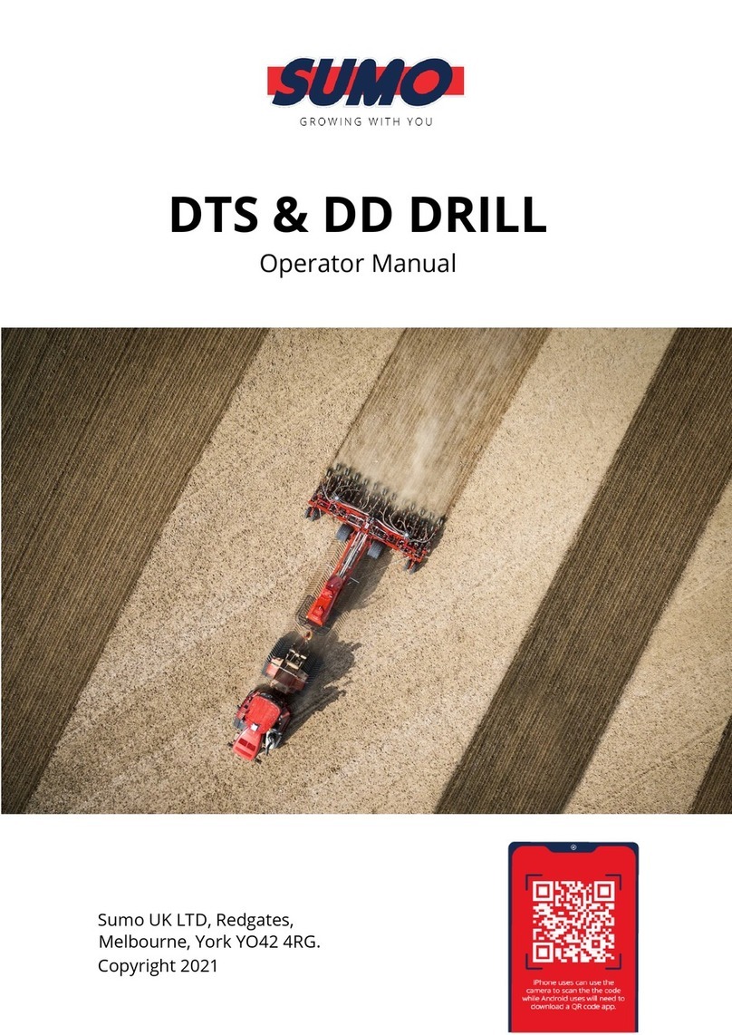
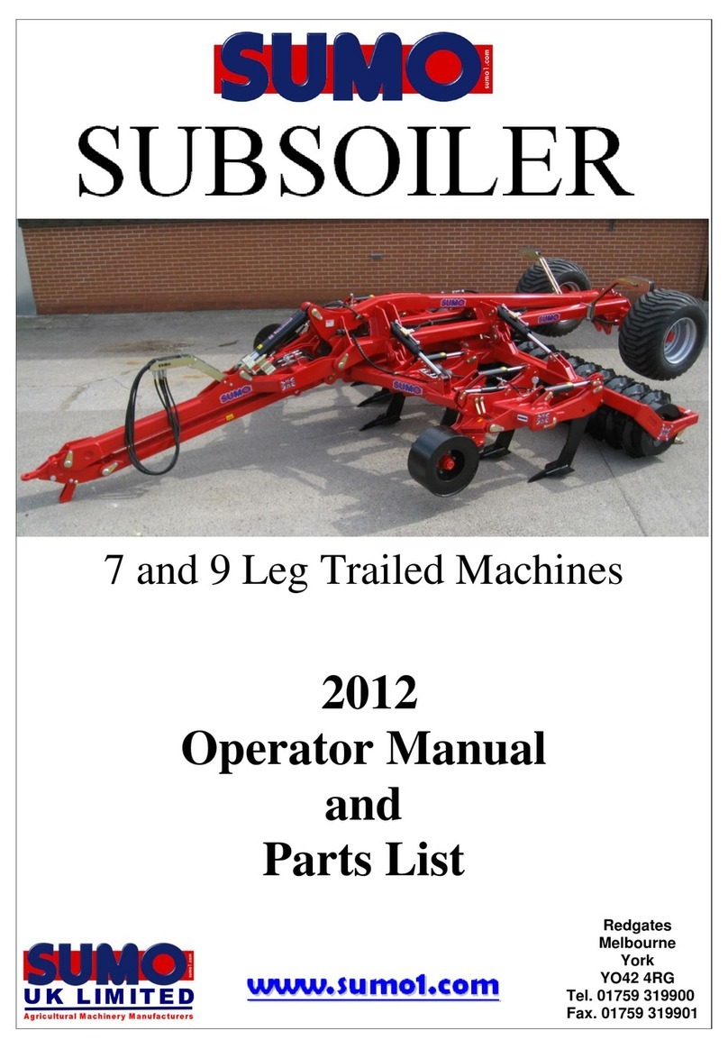
Sumo TRIO Installation and maintenance instructions

3m, 3.5m machines
2014
Operator Manual
and
Parts List
Redgates
Melbourne
York
YO42 4RG
Tel. 01759 319900
Fax. 01759 319901


1.0 Registration
To activate your SUMO Warranty, you must complete this page and send it
back to us at: Sumo UK Ltd
Redgates
Melbourne
York
YO42 4RG
Tel. 01759 319900
Fax. 01759 319901
(NO REGISTRATION = NO WARRANTY)
SUMO SERIAL No:
For your own records.
(Serial plate on side of headstock)
Sumo Trailed Trio Registration Document
NAME:
ADDRESS:
Telephone Number:
SUMO SERIAL No.
(Serial plate on
side of headstock)
DEALERSHIP
NAME AND
BRANCH:
COMMENTS:
Postcode:
DATE:

In order to obtain your free pair of Sumo overalls and baseball cap please
fill in this form and send back to us at:
Sumo UK Ltd
Redgates
Melbourne
York
YO42 4RG
Tel. 01759 319900
Fax. 01759 319901
SUMO SERIAL No:
Overall size:
tick where applicable
NAME:
ADDRESS:
Small (38 chest)
Medium (42 chest)
Large (46 chest)
Extra large (50 chest)
XX Large (54 chest)
XXX Large (58 chest)
Postcode:
Page 2

2.0 Summary
The SUMO Trio, a unique one pass soil conditioning machine designed and manufactured in Britain,
comprising as its name suggests of three parts, each of these tuned to comprehensively create the finish
required.
Firstly
The ultra low draught shear bar protected Subsoiler legs are mounted in a staggered pattern on a heavy
duty toolbar, adjusting to a maximum depth of 400mm (at the point) via pins. Due to the design of the
legs and their mounting, when an obstruction is encounterd, both the first and second rows of legs trip in
a fashion which allows the point to come clear of the ground and to pass by the obstacle. These legs
feature quick change points, shins and leg wear protectors.
Secondly
A double row of 500mm concave discs, mounted in pairs on independently suspended arms giving a
shock-proof durable system with quality low maintenance triple sealed taper roller bearings. Double
mounting gives unrivalled performance when working in adverse conditions.
Finally
The patented Multipacka is uniquely designed to fulfil a number of criteria, comprising, 609mm x 10mm
tube mounted on heavy duty quality bearings fitted with notched cutting/drive rings to keep turning in
arduous conditions, giving a total diameter of 800mm. The ring shoulders feature a convex shape adjacent
to the barrel, creating consolidation and cracking even on the top of the ridge. All these features make a
packer which presses and firms to a higher quality with a lower power requirement than any other packer
available.
Before using the SUMO Trio it is absolutely necessary that you read this Operators Manual and Safety
Instructions attentively.
Specifications, descriptions and illustrations in this brochure are accurate, as known, at the time of
publication but may be subject to change.

Table of Contents
1.0 Registration
2.0 Summary
3.0 Table of Contents
4.0 Safety
4.1 Qualification and Training
5.0 General safety
5.1 Special safety instructions
6.0 Operation and Adjustment
6.1 Operating
6.2Adjustment
6.3 Auto - Reset legs
7.0 Maintenance
7.1 Spares
7.2 Winter storage
8.0 Parts and Assembly
8.1 Drawbar
8.2 Leg assembly Auto-reset
8.3 Single Disc Unit Assembly
8.4 Twin Disc Unit Assembly
8.5 Axel Assembly
8.6 Leg Assembly Auto - Reset
8.7 Alternate leg Assembly
8.8 Active Soil retainer
8.9 Packer, Scraper and bearing Assembly
8.10 Light Assembly
8.11 Main frame
8.12 Packer depth
8.13 Front Disc cleaner
8.14 Ball Hitch
8.15 Front right disc assembly
8.16 Front left disc assembly
8.17 Axle hydraulics assembly
8.18 Auto- reset hydraulics
8.19 Stickers and paint

4.0 Safety
This manual contains basic advice which should be observed during setting-up, operation and
maintenance. Therefore, this operating manual must be read by the personnel concerned prior to starting
up, using the machine and be available at all times.
If safety instructions are not complied with, then this can lead to the risk of injury to yourself and others
as well as damage to the environment or the machine. Non-compliance to the safety instructions can also
lead to claims for damages becoming invalid.
4.1 Qualification and Training
Ensure that only reliable, authorized personnel work on or with the machine. Statutory minimum
age limits must be observed.
Employ only trained or instructed staff; the individual responsibilities of the personnel concerning
operation, setting up, maintenance and repair must be clearly established.
Define the machine operators’ responsibilities – also with regard to observing traffic regulations.
The operator must have the authority to refuse any instructions issued by third parties, which
contravene safety.
Persons undergoing training or instruction or taking part in a general training course should not be
allowed to work on or with the machine unless they are under the constant supervision of an
experienced person.
The use of spare parts, accessories and ancillary equipment not supplied and/or not approved by
SUMO could have detrimental effects to the construction of the SUMO machine or on its
functions and hence impair the active and/or passive driving and/or operational safety (accident
prevention).
SUMO shall not be responsible for any damage caused by the use of spare parts, accessories and
ancillary equipment not supplied and/or approved by SUMO.
Conversions of or modifications to the machine may only be carried out after consultation with
SUMO.

5.0 General safety
Warning signs and other notices on the machine provide important information for the safe
operation. Observing them will serve your safety.
Before starting work, make yourself familiar with all the equipment and controls as well as their
functions.
The user should wear close-fitting clothing.
Keep the machine and in particular the bearings clean to avoid risk of fire.
Check around the machine before moving off or starting up (watch out for children!). Make sure
you have adequate all-round visibility.
Always match your speed to the local conditions. Avoid sudden turning manoeuvres when driving
uphill or downhill or when travelling across a slope.
Observe the respective regulations when using public roads.
Take into account the length, the wide overhang, the folded height and the sideways force acting
on the machine when turning or negotiating curves.
5.1 Special safety instructions
Take extreme care when hitching up or unhitching machine to/from the tractor.
Never allow persons to stand between the tractor and the machine unless the tractor is secured
against rolling away by means of parking brake and/or wheel chocks.
During transport, secure the packer (using both pins) to prevent shock loading when encountering
road undulations.
It is forbidden to allow persons to ride on the machine at any time. A safe distance should be
maintained from the machine by observers when in work.
Never stand or work beneath suspended loads.
Ensure all persons are stood clear of the machine when folding or unfolding.
When making adjustments to the machines care should be taken not to trap any body parts in
moving or pivoting parts.
When making adjustments to the machine the tractor engine should be switched off to prevent the
hydraulics from operating.

6.0 Operation and Adjustment
6.1 Operating
Optimum soil conditioning will occur when the Trio wing frames are running horizontal (parallel with the
ground). The recommended method to set up the machine to run level requires the desired working depth
to be set via pin adjustment on the packer, and then to bring the wings level, add or remove slices from
the drawbar ram. The chassis should run slightly nose end down.
Forward working speed should be governed by the local conditions as well as the finish produced by the
Sumo Trio.
When uncoupling and parking the trio up, the linkage headstock stands should be set down but only to
carry the weight of the linkage. The weight of the rest of the machine should be spread over the soil
engaging elements (roller, discs, legs ect....)
6.2 Adjustments
Depth adjustment of the Subsoiler legs is achieved by firstly removing the R-clip and the shear pin on a
Shear pin machine or alternatively just the leg pin on a Auto reset. The leg can then be lifted or lowered
to the required position and then the shear pin and clip should be replaced. The maximum leg depth is 400
mm. The easiest and most accessible way to change the leg depths (if available) is to fold the wings up
and slide the legs in or out.
To adjust the disc working depth, the weight must first be taken off the packer arms before the lynch pins
and depth pins are removed. A new depth position can then be selected by replacing the pins in higher or
lower holes. The disc unit slices, mixes and cultivates the top 50 - 100mm of soil.
6.3 Auto-Reset Legs
The pressure in the hydraulic circuit controlling the auto-reset Subsoiler legs can be altered depending on
circumstances and preference up to a maximum of 120 bar. (Exceeding this pressure may result in
damage to the machine). The higher the hydraulic pressure, the more resistance the legs have to tripping.
To alter the pressure in the hydraulic circuit:
1. Fold wings down
2. Change line A of the Auto- Reset circuit.
3. The pressure is set according to the Auto-Reset valve block (mounted on the side of the chassis).
The large gold/silver knob with lock-off ring can be adjusted in & out.
Wind in for more resistance.
Try one at at a time.
4. Once a change has been made to the pressure setting, cycle the legs up and down again to set the
pressure in the circuit.
5. Even though the pressure is locked in the circuit, this system does remain active in that the legs
work position
DO NOT TIGHTEN POINTS UP WITH AIR RACHETS OR OVER TIGHTEN WITH
SPANNERS. EXCESSIVE TIGHTENING WILL RESULT IN POINTS CRACKING

7.0 Maintenance
The packer bearings should be greased with one pump once a week and after washing off.
The disc bearings should be greased until old grease is forced out once a week when in normal use and
after washing off.
The condition of the subsoiler legs, the points and the discs should be regularly monitored in order to
maintain the most efficient use of the machine.
Wheel studs should be checked that they tight after the first 10hrs operation and again regularly every
week when in use. They should be tightened to a torque setting of 270Nm.
Tyre pressures should be set to 20 PSI and regularly checked
The condition and position of the packer scrapers should also be observed in order to prevent soil
building up on the packer. Ensure the scrapers are not touching the packer though, as this will add rolling
resistance as well as causing premature wear of the packer.
Grease points requiring one pump every 50 hours are located on rams, exposed chrome ram rods should
also be greased weekly to prevent these valuable parts from rusting and causing costly oil leaks.
7.1 Spares
When ordering replacement parts please have your serial number, part numbers (listed in Section 6.0) and
quantities at hand.
7.2 Winter storage
When machines are to be parked up for the winter period, correct storage techniques are an important part
of protecting the machine to ensuring a hassle free season. When the machine has finished work it should
be cleaned down and washed off to remove all traces of soil.
Following washing off, the packer bearings should be greased with one pump and the disc bearings
should be greased until old grease is forced out. Other grease points are located on all rams, wing hinge
bushes and drawbar hinge bushes, and these should receive two or three pumps of grease.
Wheel studs should be checked that they are tight. Tyre pressures should also be checked to ensure there
is not a slow puncture before entering storage.
When the machine is parked up a note should be made of what wearing parts require replacing ready for
the next seasons work. The wearing parts can then be ordered in time ready for the next season’s work in
good time to avoid delays when the machine is required earlier than expected!

8.0 Parts and Assembly
8.1 draw bar Page 9
8.2 Leg assembly –Auto reset Page 10
8.3 Single disc unit Page 11
8.4 Twin disc unit Page 12
8.5 Axle Assembly Page 13
8.6 Leg assembly Auto-Reset Page 14
8.7 Alternative leg Assembly Page 15
8.8 Active Soil Retainer Page 16
8.9 Packer, scraper and bearing Assembly Page 17
8.10 Light Assembly Page 18
8.11 Main Frame Page 19
8.12 Packer depth Page 20
8.13 Front disc cleaner Page 21
8.14 Ball Hitch Page 22
8.15 Front right disc assembly Page 23
8.16 Front left disc assembly Page 24
8.17 Axle hydraulics Page 25
8.18 Auto - reset Hydraulics Page 26
8.19 Stickers and Paint Page 28

8.19 stickers and paint
Sticker
Description
Quantity
Part No.
Big Sumo horizontal sticker
450 x 125mm
2
SWB125
Big Trio sticker
320 x 125mm
2
SWB126
Big Union Jack sticker
150 x 100mm
2
SWB127
Vertical Sumo sticker
80 x 295mm
2
SWB128
Small Union Jack sticker
2
SWB129
Small Sumo Horizontal
Sticker
4
SWB130
Sumo touch - up paint
Sumo Red
1/2 Litre
SWB131
Sumo Black
1/2 Litre
SWB132

1 2 5
4
3
1 2
67
Sumo rigid trailed trio
Drawbar
MH
04/07/2013
8.1 Drawbar
ITEM:
PART NO:
DESCRIPTION:
1
SWM30200
M30 Flat washer
2
SWM30004
M30 Nylock
3
SWB186
hitch spoon
4
SWM3090
M30 X 90 Bolt
5
SW1315
Drag link
6
SWM30190
M30 X 190 Bolt
7
SW197
Front drawbar insert
TITLE:
DO NOT SCALE DRAWING
DATE:
INITIAL:
REVISION:
Drawings and design information found
herein remain the sole property of Sumo
UK Ltd. Reproductions may only be
made with the permission of the owner.
MACHINE/COMPONENT:

1
2
3
4
5 6
7
8
10
11
12
13
14
15
9
ITEM NO.
PART NO.
DESCRIPTION
1
SW1017
Cast Socket
2
SWH328
705/1 Ram
3
SWB374
Spring Tension
Bush 30x36x25
4
SWM30200
M30 x 200 Bolt
5
SWM30001
M30 Washer
6
SWM30004
M30 Nylock Nut
7
SW183
30mm x 170mm
Tabbed Pin
8
SW188
30x40x45mm PB1 Bush
9
SW1192
30mm x 120mm
Tabbed Pin c/w
Grease Nipple
(L/H & R/H)
10
SWM1240
M12 x 40 Bolt
11
SWM12130
M12 x 130 bolt
12
SWM12001
M12 Washer
13
SWM12004
M12 Nylock Nut
14
SWB105
Lynch Pin
15
SW451
Leg Depth Pin
TITLE:
DO NOT SCALE DRAWING
DATE:
INITIAL:
REVISION:
Drawings and design information found
herein remain the sole property of Sumo
UK Ltd. Reproductions may only be
made with the permission of the owner.
MACHINE/COMPONENT:
08/07/2013
Sumo rigid trailed trio
Auto Reset Assembly
MH
8.2 Leg assembly - Auto reset

1
2
3
4
5
6
7
8
9
10
11
12
13
16
15
14
17
18
ITEM
NO.
PART NO.
DESCRIPTION
1
SW390 (L/H) &
SW391 (R/H, Not
Shown)
Disc Arm
2
SW107
Clamp Plate
3
SWB103
Rubber
4
SWM1235CHSQ
M12 x 35 Cup
Head Square
5
SWM12005
M12 Flanged
Nut
6
SWB102
Bearing
7
SW109
Single Disc
Axle
8
SWB101
20" Scalloped
Disc
9
SWM30004
M30 Nylock
Nut
10
SWM30001
M30 Washer
11
SW103
Dust Cover
and Convexed
Disc
12
SW108
Disc Axle
Washer
13
SWM16006
M16
Locking
Nut
14
SWM16001
M16 Washer
15
SWM16120
M16 x 120 Bolt
16
SW1153
M16 Washer
(Thick)
17
SW646
Disc Scraper
18
SWM1240CHSQ
M12 x 40 Cup
Head Square
TITLE:
DO NOT SCALE DRAWING
DATE:
INITIAL:
REVISION:
Drawings and design information found
herein remain the sole property of Sumo
UK Ltd. Reproductions may only be
made with the permission of the owner.
MACHINE/COMPONENT:
MH
Single Disc Unit Assembly
8.3 Single Disc Unit Assembly
08/07/13
Sumo rigid trailed trio

1
2
3
4 5
6
7
8
910
12
11
13
14 17
15
16
1820
21
ITEM
NO.
PART NO.
DESCRIPTION
1
SW391 (R/H. Not
Shown) & SW390
(L/H)
Disc Arm
2
SW107
Clamp Plate
3
SWB103
Rubber
4
SWM1235CHSQ
M12 x 35 Cup
Head Square
5
SWM12005
M12 Flanged
Nut
6
SWB102
Bearing
7
SW101
Twin Disc Axle
8
SWB101
20" Scalloped
Disc
9
SWM3004
M30 Nylock
Nut
10
SWM30001
M30 Washer
11
SW103
Dust Cover
and Convexed
Disc
12
SW102
Dust Cover
and
Concaved
Disc
13
SW108
Disc Axle
Washer
14
SWM16006
M16
Locking
Nut
15
SWM16001
M16 Washer
16
SWM16120
M16 x 120 Bolt
17
SW1153
M16 Washer
(Thick)
18
SW646
Disc Scraper
19
SWB184
18" Scalloped
Disc (end of
disc row, Not
Shown)
20
SWM1240CHSQ
M12 x 40 Cup
Head Square
21
SWM12001
M12 Flat
washer
Twin disc unit Assembly
Sumo rigid trailed trio
TITLE:
DO NOT SCALE DRAWING
DATE:
INITIAL:
REVISION:
Drawings and design information found
herein remain the sole property of Sumo
UK Ltd. Reproductions may only be
made with the permission of the owner.
MACHINE/COMPONENT:
DATE:
08/07/13
MH
8.4 Twin Disc Unit

1
2
34
3 4 10 11 6
8
7
9
5
12
13
8.5 Axle Assembly
MH
09/07/2013
Axle Assembly
Sumo rigid trailed trio
ITEM:
PART NO:
DESCRIPTION:
1
SW235 50 X 190 Tabbed pin
2
SWM1240
M12 x 40 Bolt
3
SWM12001
M12 Flat washer
4
SWM12004
M12 Nylock nut
5
SWH125
705-2 Ram
6
SW1318
Ram stop bushes
7
SW1319
Large ram stop retainer
washer
8
SWM30180
M30 x 180 Bolt
9
SWM30004
M30 Nylock nut
10
SW661
Trailed trio ram stop
frame
11
SWB440
M12 X 35 Rubber bump
stop
12
SWB142
Oilite Bush
13
SW791
Spring tension bush
TITLE:
DO NOT SCALE DRAWING
DATE:
INITIAL:
REVISION:
Drawings and design information found
herein remain the sole property of Sumo
UK Ltd. Reproductions may only be
made with the permission of the owner.
MACHINE/COMPONENT:

1
2
3
4
7
89
5 6
12
10
DO NOT TIGHTEN POINTS UP WITH AIR RACHETS OR
OVER TIGHTEN WITH SPANNERS.
EXCESSIVE TIGHTENING WILL RESULT IN POINTS CRACKING
ITEM
NO.
PART NO.
DESCRIPTION
1
SW1046
Trio Leg
2
SW1048
Cast Shin
3
SWB183
M10 x 30 Roll Pin
4
SW1050
Concord Point
5
SWM1250
M12 x 50 Bolt
6
SWM12004
M12 Nylock Nut
7
SWB401/400
4" R/H Wing & L/H Wing (Not
Shown)
8
SWB366/367
8" L/H Wing & R/H Wing (Not
Shown)
9
SWM1235TN
M12 x 35 Twin Nibbed Bolt c/w
Plain Nut
10
SW1047
Trio Weld on Leg Bottom
TITLE:
DO NOT SCALE DRAWING
DATE:
INITIAL:
REVISION:
Drawings and design information found
herein remain the sole property of Sumo
UK Ltd. Reproductions may only be
made with the permission of the owner.
MACHINE/COMPONENT:
09/07/2013
Trio Leg Assembly
Sumo rigid trailed trio
MH
8.6 Leg Assembly Auto - Reset

1
56
4
7
9
8
DO NOT TIGHTEN POINTS UP WITH AIR RACHETS OR
OVER TIGHTEN WITH SPANNERS.
EXCESSIVE TIGHTENING WILL RESULT IN POINTS CRACKING
ITEM NO.
PART NO.
DESCRIPTION
1
SW777
Combi Trio Leg
2
SWM1660
M16 x 60 Bolt (not shown)
3
SWM16004
M16 Nylock Nut (not shown)
4
SW1100
Combi Trio Point
5
SW165/164
4" L/H Wing & R/H Wing (Not
Shown)
6
SW157/158
8" R/H Wing & L/H Wing (Not
Shown)
7
SWM1235TN
M12 x 35 Twin Nibbed Bolt
c/w Plain Nut
8
SW354
Trio Leg Weld on Bottom
9
SWM12004
M12 Nylock nut
SCALE 1:6
TITLE:
DO NOT SCALE DRAWING
DATE:
INITIAL:
REVISION:
Drawings and design information found
herein remain the sole property of Sumo
UK Ltd. Reproductions may only be
made with the permission of the owner.
MACHINE/COMPONENT:
MH
Alternate Trio Leg Assembly
Sumo Trio
8.7 Alternate Leg Assembly
15/05/2013

1234
56327
82
9
563
2
7
ITEM:
PART NO:
DESCRIPTION:
1
SWM2090
M20 X 90 bolt
2
SWM20001
M20 flat washer
3
SW123
12mm large
spacer
4
SW124
Crank arm
5
SW125
12mm spacer sm
6
SW126
10 MM spacer sm
7
SWM20004
M20 nylock nut
8
SWM2080
M20 X 80 bolt
9
SW418
Soil retainer left
SW419
Soil retainer right
(not shown)
TITLE:
DO NOT SCALE DRAWING
DATE:
INITIAL:
REVISION:
Drawings and design information found
herein remain the sole property of Sumo
UK Ltd. Reproductions may only be
made with the permission of the owner.
MACHINE/COMPONENT:
8.8 Active Soil Retainer
Sumo rigid Trailed Trio
Active soil retainer
09/07/2013
MH
Other manuals for TRIO
1
Table of contents
Other Sumo Farm Equipment manuals