SPECIFICATION : PB-300
PB-300P/N-12 PB-300P/N-24
MODEL
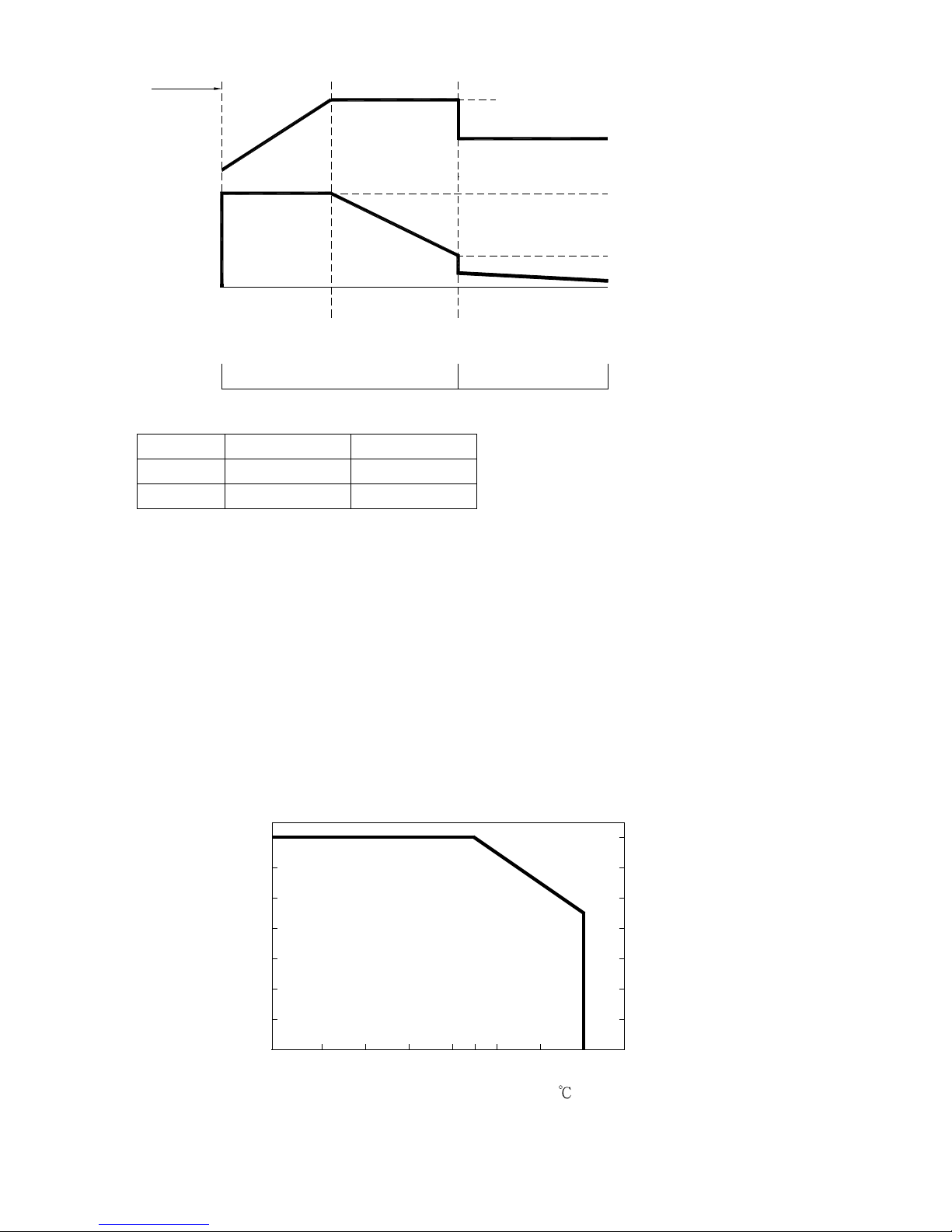
BOOST CHARGE VOLTAGE
FLOAT CHARGE VOLTAGE
OUTPUT CURRENT(max.)
CONTINUOUS OUTPUT
CURRENT (Typ.) (Note 6)
BATTERY TYPE
VOLTAGE ADJUSTABLE RANGE
RECOMMENDED BATTERY
CAPACITY(AMP HOURS)(Note 5)
OUTPUT
VOLTAGE RANGE
FREQUENCY RANGE
EFFICIENCY (Typ.)
POWER FACTOR (Typ.)
INPUT
FUNCTION
PROTE-
CTION
ENVIRO-
NMENT
INRUSH CURRENT (Typ.)
LEAKAGE CURRENT
OVER TEMPERATURE
REMOTE CONTROL (CN5)
SAFETY STANDARDS
HARMONIC CURRENT
EMI CONDUCTION & RADIATION
SAFETY &
EMS IMMUNITY
EMC
(Note 4)
WITHSTAND VOLTAGE
ISOLATION RESISTANCE
WORKING TEMP.
WORKING HUMIDITY
STORAGE TEMP., HUMIDITY
TEMP. COEFFICIENT
VIBRATION
OVER LOAD
OVER VOLTAGE
REVERSE POLARITY
AC CURRENT (Typ.)
14.4V 28.8V
13.6V
20.85A
12.5A
Open & Sealed Lead Acid
80 ~ 200Ah
13 ~ 14.7V
27.2V
26 ~ 28.8V
10.5A
6.25A
40 ~ 125Ah
90 ~ 132VAC / 180 ~ 264VAC selected by switch
47 ~ 63Hz
85%
>0.65 (with P type) at 230VAC
86%
6A/115VAC 3A/230VAC
COLD START 60A
<3.5mA / 240VAC
90 ~ 110% rated output current
15 ~ 17V
By internal fuse
30 ~ 35V
Protection type : Constant current limiting, recovers automatically after fault condition is removed
Protection type : Shut down o/p voltage, re-power on to recover
Protection type : Automatically derate charge current until zero
Open: Normal work Short: Stop Charging
EN60335-2-29 CB Approved by TUV
Compliance to EN55022 (CISPR22) Class B
Compliance to EN61000-3-2,-3 (only P type)
Compliance to EN61000-4-2,3,4,5,6,8,11; ENV50204, EN55024, Light industry level, criteria A
I/P-O/P:3KVAC I/P-FG:1.5KVAC O/P-FG:0.5KVAC
I/P-O/P, I/P-FG, O/P-FG:100M Ohms/500VDC
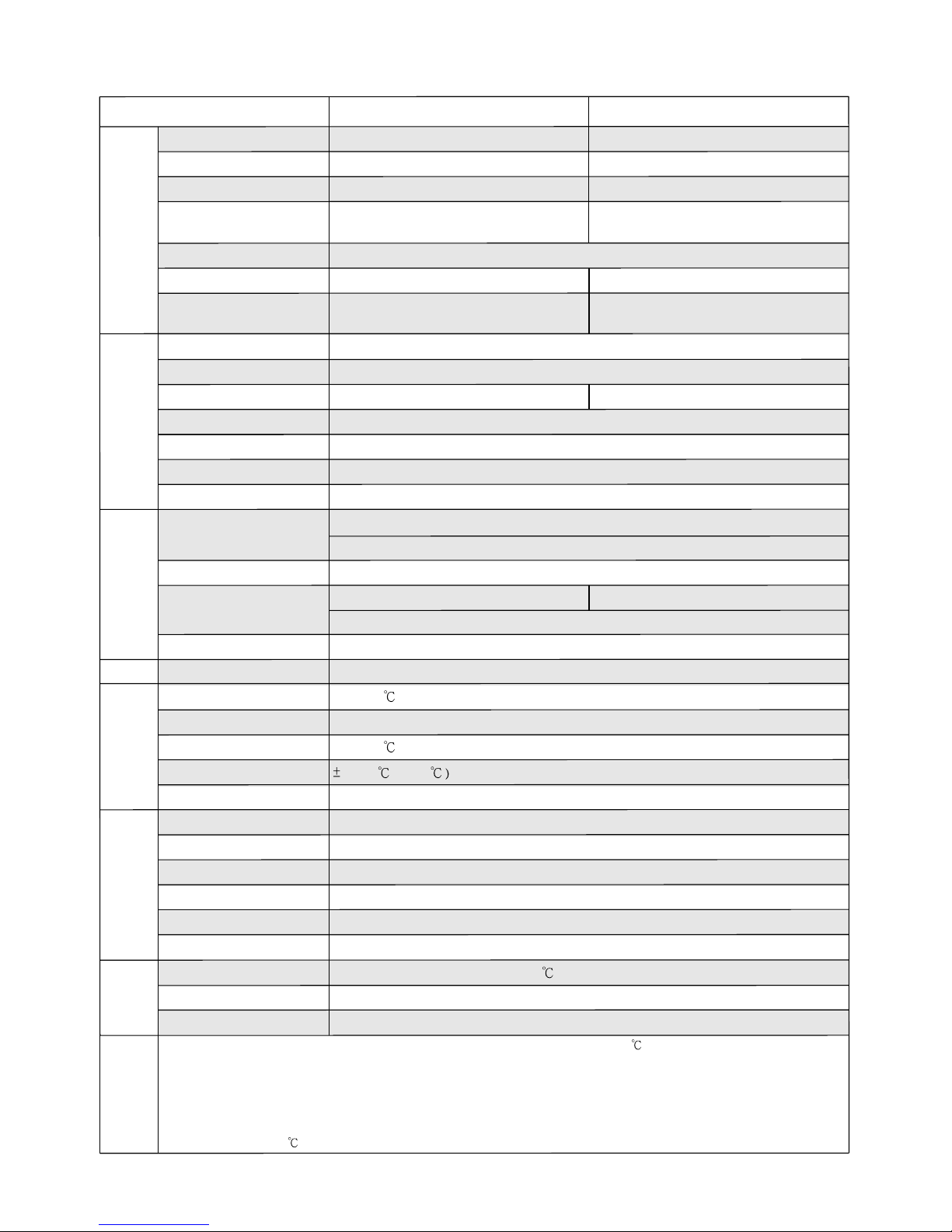
-10 ~ +40 (Refer to output load derating curve)
20 ~ 90% RH non-condensing
-40 ~ +85 , 10 ~ 95% RH
0.05%/ (0 ~ 45
10 ~ 500Hz, 2G 10min./1cycle, 60min. each along X, Y, Z axes
MTBF 115.8Khrs min. MIL-HDBK-217F (25 )
253*135*48.5mm(L*W*H)
DIMENSIONOTHERS
NOTE
PACKING 1.45Kg; 6pcs/9.7Kg/0.93CUFT
1. All parameters NOT specially mentioned are measured at 230VAC input, rated load and 25 of ambient temperature.
2. Ripple & noise are measured at 20MHz of bandwidth by using a 12" twisted pair-wire terminated with a 0.1uf & 47uf parallel capacitor.
3. Tolerance : includes set up tolerance, line regulation and load regulation.
4. The power supply is considered a component which will be installed into a final equipment. The final equipment must be re-confirmed
that it still meets EMC directives.
5. This is Mean Well's suggested range. Please consult your battery manufacturer for their suggestions about maximum charging current
limitation.
6. Test condition is at 25 , charging current will change under different temperature.