Sungrow AC007UK-01 L1 User manual

www.sungrowpower.com
AC Charger
Quick Installation Guide
AC007UK-01 L1

The contents of the document will be periodically updated or revised due to the product development. It is probably
that there are changes of document in the subsequent edition. Under no circumstances can this document replace
the user manual and the safety instructions on the product.
Please read the user manual and relevant standards and specifications carefully before performing any operation.
You can get the information by logging in Sungrow support platform via http://support.sungrowpower.com/ or
scanning the QR code on the side of the product or on the back cover of the quick installation instruction.
All operations shall only be performed by professional personnel. Professional personnel must be trained specially,
read this instruction thoroughly, master the safety instructions related to operation and be familiar with the local
standards and safety regulations of electrical system.
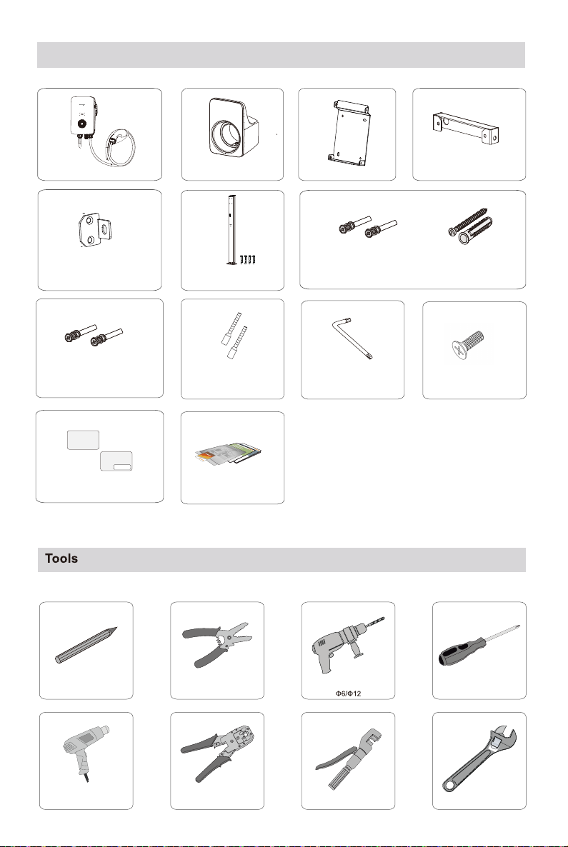
Before installing the equipment, check whether the goods are complete and consistent with the order, and whether
there is obvious damage according to the packing List. Contact the shipping company or SUNGROW directly in case
of any damage or incompleteness.
Cables used for the charger must be intact and well insulated. Use insulation tools and wear personal protective
equipment.
Violation of any of the above requirements may cause casualties or equipment damage.
Failure to comply with the requirements of this document and the user manual may cause casualties or equipment
damage, and Sungrow shall not assume any liability.
Tbgfuz!Tubufnfou
OPUJDF
During transport, the charger shall be securely packed and marked in the loading direction in a wooden box, and the charger
shall not be stored upside down.
During transport, tighten the equipment to avoid violent shaking and bumps that damage the package.
After the arrival of goods, check for transport damage and, if any, contact the shipping company or us.
Check if the devices inside the package are the same as that of the delivery list.
Keep the charger away from flammable and explosive substances. Store it in a dry, clean, and well-ventilated place, free from
harmful gases. Do not store it near the corrosive objects.
DBVUJPO
EBOHFS
High voltages are present during operation and could cause electrical shock, resulting in death, serious personal injury, or
property damage.
Non-professional personnel shall not disassemble the components.
FO!

Radio data
EU Declaration of Conformity
Radio Technology
*Technical parameters listed above apply to EU countries only.
within the scope of the EU directives:
Low Voltage Directive 2014/35/EU (LVD)
Electromagnetic compatibility Directive 2014/30/EU (EMC)
Radio Equipment Directive 2014/53/EU (RED)
The restriction of the use of certain hazardous substances (RoHS) in electrical and electronic equipment Directive 2011/65/EU
and Commission Delegated Directive (EU)2015/863
SUNGROW confi rms herewith that the products described in this document are in compliance with the fundamental
requirements and other relevant provisions of the above-mentioned directives. The entire EU Declaration of Conformity can be
found at support.sungrowpower.com.
Radio frequency band(s)
Maximum transmitted power
Function
Operating band/frequency
Maximum radiated H-fi eld
802.11b/g/n
2412~2472MHz
WIFI
19.5 dBm
13.56MHz
RFID
10 dBμA/m
The symbols on the charger body are as follows.
Disconnect the inverter from all the external
power sources before service!
There is a danger from a hot surface that may
exceed 60°C.
Danger to life due to high voltages!
Only qualified personnel can open and aintain the inverter.
Read the user manual before maintenance!
Do not dispose of the inverter together with
household waste.
RoHS labeling.
The product complies with the requirements of the
applicable EU directives.
UKCA mark of conformity.

Charger×1
Countersunk screw×6
Socket-out×1 Backplate ×1 Upper hanging plate×1
Lower hanging plate×2 Mounting pole×1
(optional)
Scope of delivery
L-shaped wrench×1
Marker Wire stripper Cross screwdriver
Hydraulic clamp:2.5-6mm2
Heat gun Crystal crimping pliers
Cable drilling tool:
Adjustable spanner
Wire end ferrule×1~2
RFID-Card×2
Card Number
Charger SN
Documents
Expansion screw×7Combination screw×4
(for wall-mounted installation)
Combination screw×11
(for pole-mounted installation)

Mounting place
125cm
Dimensions and weight
92.4mm205mm
310mm

Note: cable shall be connected before the charger is installed. Cable cross section: 3×6 mm
2
Cable connection
AC Cable connection
1
①Remove the back cover. ③Crimp the terminal. (OT2.5-5)②Thread.
M3
0.5±0.1N•m
3
2
5
④Connect the cable. ⑤Install the back cover.
M3
0.5±0.1N•m
M5
3±0.2N•m
4

RS485 Communication Connection
is about 45mm.The bearing capacity of the installation carrier shall be at least 4.5 times that of the charger!
Wall-mounted charger installation
Note: Crimp the blue wire and the blue-white wire to the crystal head.The blue line (PIN4) connects to 485B, and the
blue-white line (PIN5) connects to 485A.
①Install the backplate.
Backplate
Tapping screw
1
180°
GRID
CT
S4 85A
S4 85B
3 4
5624 25
D SU666
I*
(Whi te )
I
(Bl ue)
L N
LOAD
RS4 85A
RS 485 B
3 4
5624 25
D SU6 66
I* (Whi t e)
I(B lu e)
Connect to a Smart Energy Meter.
RJ45 terminal components (A) RJ45 terminal components (B)
1
2
3
2
1
1

②Install the socket-out .(It is recommended that the socket-out be installed at the lower right side of the charger, with a linear
distance of about 20cm from the charger. The actual situation on site shall prevail.)
2
4
1
3
③Charger installation.Wall-mounted installation effect
digram.
M4
1.2±0.1N•m
M4
1.2±0.1N•m

Pole-mounted charger installation (optional)
②Pile installation(after threading).③Install the backplate and the
socket-out.
M4
Φ12×70 mm
1.2±0.1N•m
2
3
4
1
①AC line installation
The drill size is Φ12 mm and the drilling depth is about 70 mm.
.
④Install the upper hanging plate and lower hanging
plate.
Pile installation effect digram.
M4
1.2±0.1N•m

Inspection before commissioning
Item
The charger is firmly and securely installed.
Location
Cables are correctly and firmly connected, and are adequately
protected from damage.
Charger
The AC input’s current leakage protection switch is reasonable.
Cable
Current leakage
protection
Description
Judgment
Yes No
The charger has sufficient cooling space and there is no other
stuff or components are left on the top of the charger.
Clearance
The charger is correctly mounted at a place that is convenient
for operation and maintenance.
Step 1 Ensure that all requirements are met before commissioning.
Step 2 Turn on the current leakage protection switch of the AC input.
Step 3 Power on the charger.
The blue LED blinks slowly which indicates the charger is in standby mode.
Commissioning
The status description of the LED indicators
Charger status
Blue indicator breathes, on for 1s and off for 1s; circulatingCharging
Blue indicator flashes slowly, on for 1s and off for 4s; circulatingStandby
Blue indicator is steady onCharging stops
Blue indicator flashes quickly, on for 0.5s and off for 0.5s; circulatingReady to charge
Swiping Card Blue light is on for 5 times with an interval of 0.2s
Blue indicator is on for 3s and red indicator is on for 3sCharging reservation
Blue indicator is on for 1s and red indicator is on for 1sPower-on self-test
Indicator
Blue indicator flashes quicklyCharger software upgrading

www.sungrowpower.com
Sungrow Power Supply Co., Ltd.
Npsf!jogpsnbujpo!jo!uif!RS!dpef!ps!
bu!iuuq;00tvqqpsu/tvohspxqpxfs/dpn
This manual suits for next models
1
Table of contents
Other Sungrow Batteries Charger manuals

Sungrow
Sungrow AC011E-01 User manual

Sungrow
Sungrow AC007E-01 User manual

Sungrow
Sungrow IDC30E User manual

Sungrow
Sungrow IDC30E User manual

Sungrow
Sungrow AC007UK-01 User manual

Sungrow
Sungrow AC011E-01 User manual

Sungrow
Sungrow AC011E-01 User manual

Sungrow
Sungrow AC011E-01 User manual

Sungrow
Sungrow AC011E-01 User manual

Sungrow
Sungrow AC011E-01 User manual