Sungrow AC011E-01 User manual

AC011E-
01AC ChargerUser ManualAC011E-
01-UEN-Ver13-202306
User Manual
AC Charger
AC011E-01
AC011E-01-UEN-Ver13-202306


I
All Rights Reserved
All Rights Reserved
No part of this document can be reproduced in any form or by any means without the prior
written permission of Sungrow Power Supply Co., Ltd (hereinafter "SUNGROW").
Trademarks
and other Sungrow trademarks used in this manual are owned by
SUNGROW.
All other trademarks or registered trademarks mentioned in this manual are owned by their
respective owners.
Software Licenses
• It is prohibited to use data contained in firmware or software developed by SUNGROW,
in part or in full, for commercial purposes by any means.
• It is prohibited to perform reverse engineering, cracking, or any other operations that
compromise the original program design of the software developed by SUNGROW.
Privacy Protection
• Information contained in this manual is the private property of Sungrow Power Supply
Co., Ltd. No part of this manual may be transmitted in any form without the prior written
permission of Sungrow Power Co., Ltd. Internal reproduction is allowed only for product
evaluation or other appropriate purposes.
• We declare that the network account and password data stored in the equipment system
are only used for remote control and monitoring of the equipment and will not be trans-
mitted to any third-party data platform without the user's permission.
Disposal
After the service life of the charger ends, please dispose of it in accordance with the applica-
ble electrical waste disposal act at the installation location. It can also be returned to Sun-
grow Power Supply Co., Ltd., but the relevant expenses shall be borne by your party.

II
About This Manual
The manual mainly contains product information, as well as guidelines for installation, opera-
tion, and maintenance.
Target Group
This manual is intended for qualified technicians who are responsible for the installation, op-
eration, and maintenance of the charger, and end users who need to check charger
parameters.
A qualified technician is required to meet the following requirements:
• Knowledge of electronics, electricity, and machinery, and be familiar with electrical and
mechanical schematic diagrams.
• Training in the installation and commissioning of electrical equipment.
• Be able to quickly respond to hazards or emergencies that occur during installation and
commissioning.
• Be familiar with local standards and relevant safety regulations of electrical systems.
• Read this manual thoroughly and understand the safety instructions related to
operations.
EMC
In some cases, even if the equipment is in accordance with the standard emission limits, it
can have an impact in certain application areas (some sensitive equipment is placed in the
same location; the equipment is installed close to a radio or TV receiver), and the operator is
obliged to take appropriate action to correct this situation.
How to Use This Manual
Please read this manual carefully before using the product and keep it properly in a place for
easy access.
All contents, pictures, marks, and symbols in this manual are owned by SUNGROW. No part
of this document may be reprinted by the non-internal staff of SUNGROW without written
authorization.
Contents of this manual may be periodically updated or revised, and the actual product pur-
chased shall prevail. Users can obtain the latest manual from support.sungrowpower.com
or sales channels.
Symbols
This manual contains important safety instructions, which are highlighted with the following
symbols, to ensure personal and property safety during usage, or to help optimize the prod-
uct performance efficiently.
Indicates high-risk potential hazards that, if not avoided, may lead to death or seri-
ous injury.

III
Indicates moderate-risk potential hazards that, if not avoided, may lead to death or
serious injury.
Indicates low-risk potential hazards that, if not avoided, may lead to minor or mod-
erate injury.
Indicates potential risks that, if not avoided, may lead to device malfunctions or fi-
nancial losses.
“NOTE” indicates additional information, emphasized contents, or tips that may be
helpful, e.g., to help you solve problems or save time.


V
Contents
All Rights Reserved .....................................................................................................I
About This Manual......................................................................................................II
1 Product Overview .............................................................................................1
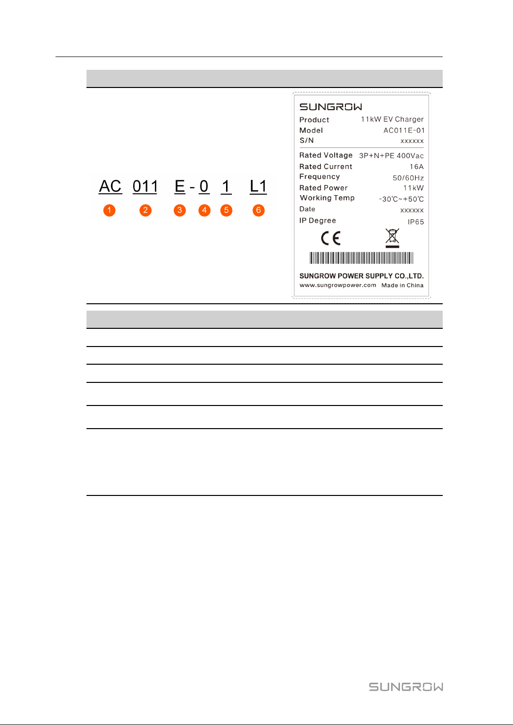
1.1 Introduction....................................................................................................1
1.2 Appearance and Dimensions...........................................................................1
1.3 LED Signals ...................................................................................................4
1.4 System Overview ...........................................................................................5
1.5 Load Management..........................................................................................7
2 Installation .........................................................................................................8
2.1 Installation Requirements................................................................................8
2.2 Unpacking and Inspection ...............................................................................9
2.3 Installation Tools........................................................................................... 11
2.4 Electrical Connection ....................................................................................12
2.4.1 Circuit Diagram ...................................................................................12
2.4.2 AC Cable Connection ..........................................................................13
2.4.3 RS485 Communication Connection ......................................................15
2.5 Wall-Mounted Installation ..............................................................................16
2.6 Pole-Mounted Installation..............................................................................19
2.6.1 Foundation Installation ........................................................................19
2.6.2 Pole Installation ..................................................................................20
3 Inspection before Commissioning ...............................................................23
4 Commissioning via iSolarCloud ...................................................................24
5 Commissioning via Web UI ...........................................................................25
5.1 Establish a Connection .................................................................................25
5.2 Configure Network........................................................................................26
5.3 Manage the Charger.....................................................................................27
5.3.1 Change the Charging Mode .................................................................27
5.3.2 Set Up Load Balancing ........................................................................27
5.3.3 Update the Firmware...........................................................................28
6 Commissioning via iEnergyCharge .............................................................30

VI
6.1 Access iEnergyCharge .................................................................................30
6.1.1 Download and Install ...........................................................................31
6.1.2 Sign up and Log in ..............................................................................31
6.2 Operation.....................................................................................................32
6.2.1 Establish a Connection........................................................................32
6.2.2 Add the Charger to Your Account .........................................................33
6.2.3 Scan the QR Code to Charge...............................................................34
6.2.4 Add RFID Charge Cards......................................................................34
6.2.5 Regulate Current During Charging........................................................35
6.2.6 Set Up Load Balancing ........................................................................35
6.2.7 Enable Offline Charging.......................................................................36
6.3 Configuration ...............................................................................................36
6.3.1 Configure Network ..............................................................................36
6.3.2 Update the Firmware...........................................................................37
7 Troubleshooting ..............................................................................................38
8 Appendix ..........................................................................................................42
8.1 Technical Data .............................................................................................42
8.2 Additional Information ...................................................................................43
8.3 Quality Assurance ........................................................................................43
8.4 EU Declaration of Conformity ........................................................................44
8.5 Contact Information ......................................................................................44

1
1 Product Overview
1.1 Introduction
The AC011E-01 charger (hereinafter referred as "charger" or "AC-Charger") is used for AC
charging of electric vehicles (BEV/PHEVs) and can be either wall-mounted or pole-mounted,
with the following advantages.
Ease of Use
EV drivers can start and stop charging via RFID charge card, iSolarCloud or iEnergyCharge.
When the vehicle is fully charged, the charging will stop. The charger also supports plug&-
play, which means the charging starts automatically as soon as the charging connector is
plugged into the vehicle.
Smart and Easy Management
In addition to the LED lights on the charger that indicate charging status, EV drivers can vis-
ualize and control the charging session remotely via iSolarCloud or iEnergyCharge.
Sustainability
With an IP65 rating, the charger is water and dust proof, allowing for outdoor use and
maintenance.
1.2 Appearance and Dimensions
Model and Nameplate
The charger comes with two versions to meet different energy-saving needs:
• AC011E-01 (hereinafter referred as "the advanced version")
• AC011E-01 L1 (hereinafter referred as "the standard version")

2
Model Nameplate
Position Description Note
1 AC Charger -
2 Nominal power (kW) -
3 European standard -
4 Screen configuration • 0: without screen
5M1 card configuration • 1: with card
6 Version (Optional) • Default: version for usage together with
SHRT for 3-phase combo-solution
• L1: version for usage as stand-alone AC
Charger
1 Product Overview User Manual

4
Dimensions
figure 1-2 Dimensions (in mm)
1.3 LED Signals
table 1-2 LED Signals
LED Signal Description
The blue LED blinks slowly (on for 1 s and off for 4 s) Standby mode
The blue LED blinks (on for 1 s and off for 1 s) Vehicle charging
The blue LED is glowing Charging ended
The blue LED blinks quickly (on for 0.5 s and off for 0.5 s) Vehicle plugged in
The blue LED blinks quickly for five times (on for 0.2 s and
off for 0.2 s) RFID charge card used
The blue LED blinks slowly (on for 2 s and off for 2 s) No RS485 communication in
standby mode under EMS
The blue LED is on for 1 s and the red LED is on for 1 s Power-on self-test
The blue indicator blinks quickly Firmware upgrading
1 Product Overview User Manual

5
1.4 System Overview
In both charging scenarios, with standard and advanced version, smart charging
visualization via App is possible. In addition to charging from the grid, the ad-
vanced versions support intelligent energy consumption usage in combination
with SUNGROW's 3-phase combo solution.
Stand-alone EV Charger
figure 1-3 System topology diagram of EV charger
Position Description Note
AUtility grid TT, TN-C, TN-S, TN-C-S.
BDTSU666 Smart En-
ergy Meter (optional)
A smart energy meter that monitors power usage
and helps to avoid power outages caused by
peak electricity during home charging.
CCharger • AC011E-01
• AC011E-01 L1
D Electric vehicle -
User Manual 1 Product Overview

6
Solar-Storage-Charging Solution
figure 1-4 System topology diagram of the solar-storage-charging solution
Position Description Note
APV strings Compatible with monocrystalline silicon, polycrystal-
line silicon, and thin-film modules without grounding.
B Inverter SH5.0RT / SH6.0RT / SH8.0RT / SH10RT
CEnergy meter
A smart energy meter that monitors power usage
and helps to avoid power outages caused by peak
electricity during home charging.
DUtility grid TT, TN, TN-C-S, TN-S, TN-C. The type of grid
grounding system depends on local regulations.
EBattery A Li-ion battery.
FBackup loads Protected house loads directly connected to the
inverter.
G Normal loads Non-protected house loads. They will be discon-
nected in case of grid failure.
HAC-Charger AC011E-01
For SUNGROW's solar-storage-EV charging solution, please refer to the user
manual of related inverter. See "8.2 Additional Information".
1 Product Overview User Manual

7
1.5 Load Management
Load management is supported by the AC-Charger. To enable load balancing
function, see "5.3.2 Set Up Load Balancing via Web UI"or "5.3.2 Set Up Load Bal-
ancing via iEnergyCharge".
figure 1-5 System topology diagram of Load Balancing
Position Description Note
ADTSU666 Smart En-
ergy Meter (optional)
A smart energy meter that monitors power usage
and helps to avoid power outages caused by
peak electricity during home charging.
BUtility grid TT, TN-C, TN-S, TN-C-S.
C House loads Energy consumed by home appliances.
DCharger • AC011E-01
• AC011E-01 L1
User Manual 1 Product Overview

8
2Installation
Respect all local standards and requirements during mechanical installation.
Any damage or malfunction with the charger caused by negligence or improper
use will not be eligible for service and replacement under the warranty.
2.1 Installation Requirements
Location Requirements
Select an optimal mounting location for safe operation, long service life and expected
performance.
• The charger with protection rating IP65 can be installed both indoors and outdoors.
• The charger should be installed at a place where the LED signals can be easily seen,
and is convenient for electrical connection, operation, and maintenance.
Environment Requirements
• There must be no flammable hazards or ignition risks.
• The mounting location must be inaccessible to children.
• The ambient temperature and relative humidity must meet the following requirements.
• Avoid exposure to direct sunlight, rainwater and snow.
• The charger should be well-ventilated for good air circulation.
• The mounting location must be away from living area. The charger will emit noises dur-
ing operation that might be perceived as disturbing.

9
Carrier Requirements
The mounting structure where the charger is installed must comply with local/na-
tional standards and guidelines.
• The carrier should be solid enough to bear 4.5 times the weight of the charger.
• The carrier should be suitable for the dimensions of the charger.
• The surface of the carrier must be fire-resistant.
Angle Requirements
• Install the charger vertically.
• Do not install the charger horizontally, tilted or upside down.
• Do not install the charger on a tilted surface.
2.2 Unpacking and Inspection
After receiving the product, check whether the appearance and structural parts of
the device are damaged, and check whether the packing list is consistent with the
actual ordered product. If there are problems, do not install the device and contact
your distributor first. If the problem persists, contact SUNGROW in time.
User Manual 2 Installation

11
Item Name Quantity
H L-shaped spanner 1
I Wire end ferrule 1~2
J RJ45 screw connector 1
K DTSU666 Smart Energy Meter
(optional) 1
L RFID charge card 2
MQuick Installation Guide, Warranty
Card, and Certificate of Conformity 1, 1, 1
The scope of delivery does not include the optional mounting pole (F) and energy
meter (K). These items must be ordered separately. Contact customer service for
details.
2.3 Installation Tools
table 2-2 Label Descriptions
Item Name Specification
A Marker -
B Wire stripper -
C Hammer drill Ø6, Ø12
D Screwdriver M3, M4
E Heat gun -
User Manual 2 Installation

12
Item Name Specification
F RJ45 crimping tool -
G Hydraulic plier 2.5-6 mm2
H Adjustable spanner -
2.4 Electrical Connection
2.4.1 Circuit Diagram
figure 2-1 Circuit diagram
table 2-3 Label Descriptions
Label Description
A The LED lights that indicates the status of the charger
B RS485, reserved for external communication
C ESP32 module for Wi-Fi communication
D CT for leakage current detection
E Charging cable output (connected to the vehicle)
F CCU internal relay
G Type A residual-current device (Parameter: 25 A/400 V with a rated residual
current of 30 mA; input cable cross-section: 2.5 mm2)
H The charger
The charger already integrates a DC residual-current device with a rated residual
current of 6 mA. However, the charger also requires a type A RCD of 30 mA. Each
charger in the system must be individually connected to the utility grid through an
RCD and a miniature circuit breaker.
2 Installation User Manual
Other manuals for AC011E-01
5
Table of contents
Other Sungrow Batteries Charger manuals

Sungrow
Sungrow AC011E-01 User manual

Sungrow
Sungrow AC011E-01 User manual

Sungrow
Sungrow AC011E-01 User manual

Sungrow
Sungrow AC011E-01 User manual

Sungrow
Sungrow AC007UK-01 L1 User manual

Sungrow
Sungrow IDC30E User manual

Sungrow
Sungrow AC007E-01 User manual

Sungrow
Sungrow IDC30E User manual

Sungrow
Sungrow AC007UK-01 User manual

Sungrow
Sungrow AC011E-01 User manual