manuals.online logo
Brands
  1. Home
  2. •
  3. Brands
  4. •
  5. Leviton
  6. •
  7. Controllers
  8. •
  9. Leviton CN221 User manual

Leviton CN221 User manual

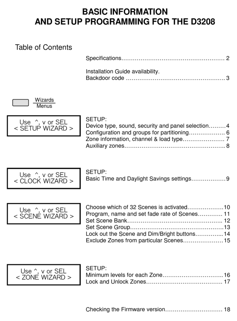
FEATURES
• Leviton's Decora® Style design • Separate Bright, Dim, On and Off Buttons
• Enables settings of Controller • Color conversion available
• Low-Voltage for easy installation • Fits standard wall box
INTRODUCTION
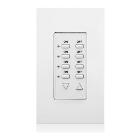
The Dimming Controller, Cat No. CN221, allows easy to use manual control of a Centura Lighting Control System. The Controller has separate ON, OFF, BRIGHTand DIM buttons to provide
simple control of your Power Pack. The Controller allows manual control of your lights and programming of the Power Pack from a standard wall box in an easy to reach location. In using the
Controller, you may override the automatic operation of the Power Pack to give the most convenience to your lighting needs.
DESCRIPTION
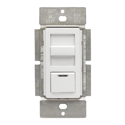
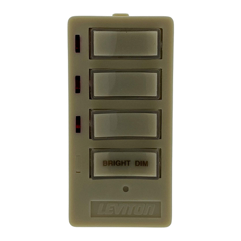
The Controller has a user friendly rocker within the rocker design (refer to Figure 1). There are four functions on the face; from top down they are ON (large upper rocker), BRIGHT (small
upper rocker), DIM (small lower rocker) and OFF (large lower rocker). The Brightness Level Display on the left indicates the current light level. The Controller has a removable face so that the
colors can be changed (refer to Figure 2).
The Controller is a component of the Lighting System. It is used to provide local user control of the lights and allows programming of the Power Pack. The Controller provides the ability to
program the MAX, MIN, UnOccupied and Light Maintain light levels, in addition to Manual Time-out and the Power Pack address for multiple Power Pack installations.The programming
sequence is described under the “TO OPERATE” section.
FCC COMPLIANCE STATEMENT
This device complies with part 15 of the FCC Rules. Operation is subject to the following two conditions: (1) This device must not cause harmful interference, and (2) This device must accept
any interference received, including interference that may cause undesired operation.
INSTALLATION INSTRUCTIONS
WARNING: TO BE INSTALLEDAND/OR USED IN ACCORDANCE WITHAPPROPRIATE ELECTRICAL CODESAND REGULATIONS.
WARNING: IF YOU ARE NOT SURE ABOUTANY PART OF THESE INSTRUCTIONS, CONSULT A QUALIFIED ELECTRICIAN.
CAUTION: DISCONNECT POWER WHEN SERVICING FIXTURE OR CHANGING LAMPS.
CAUTION: The Controller operates off of low-voltage (24VDC), so care must be taken when replacing a light switch. CONSULT LOCAL BUILDING CODES AND REGULATIONS FOR
PROPER LOW-VOLTAGE INSTALLATION.
TO INSTALL:
1. WARNING: TO AVOID FIRE, SHOCK, OR DEATH; TURN OFF POWER AT CIRCUIT BREAKER OR FUSE AND TEST THAT POWER IS OFF BEFORE WIRING!
2. Remove existing wallplate and switch or dimmer, if applicable
CAUTION: IF APPLICABLE, ENSURE THAT CIRCUIT CONDUCTORS ARE PROPERLY CAPPED OFF WITH WIRE CONNECTORS AND REMOVED FROM WALL BOX.
3. Connect lead wires per appropriate WIRING DIAGRAM as follows: Twist strands of each lead tightly and, with low-voltage wires, push firmly into appropriate wire connector. Screw
connectors on clockwise making sure that no bare conductor shows below the wire connectors. Secure each connector with electrical tape.
4. Carefully position all wires to provide room in outlet box for Controller. Mount Controller into box with mounting screws supplied.
5. Restore power at circuit breaker or fuse. Turn the Controller ON by pressing the upper half of the rocker. The GREEN ON/OFF LED will turn OFF to indicate the Controller is ON (when the
Controller is OFF, the LED is ON).
NOTE: If programming is desired proceed to “PROGRAMMING” section, otherwise continue with Step 6.
6. Attach Decora®Screwless wallplate. INSTALLATION IS COMPLETE.
PROGRAMMING
NOTE: Use large rockers to cycle programming steps and small rockers for selection of level or setting.
1. Pull off the Decora®Screwless Wallplate. Reverse wallplate and adhere Programming Label to the inside so that label is facing out(refer to
Figure 4). This label is to be used as a programming guide.
2. Using a small screwdriver or pen-point, press the program button (refer to Figure 3).LED #1 will flash to indicate the Manual Time-out
selection. NOTE: When any of the LED’s 1-5 flash, the Controller is in the program mode. Place wallplate over frame of the Controller. For
multi-gang installations, refer to Figure 4.
3. LED #5 will be lit indicating the Manual Time-out default Enabled (YES). To program Manual Time-out Disabled (NO), press the small lower
rocker. LED #6 will be lit indicating Time-out NO. To return to default YES, press the small upper rocker.
4. To program Maximum Light Level, press the large lower rocker (refer to Figure 4). LED #2 will flash indicating the Maximum Light Level selection.
Press the small upper or lower rocker to adjust lights to the desired maximum level. NOTE: The Brightness Level Display will not show the light level when the Controller is in Program mode.
5. To program the Light Maintain Level, press the large lower rocker (refer to Figure 4). LED #3 will flash indicating the (Daylight) selection. Press the small upper or lower rocker to adjust
lights to the desired level maintained by the photocell.
6. To program the UnOccupied mode, press the large lower rocker (refer to Figure 4). LED #4 will flash indicating the UnOccupied mode selection. LED #6 will be lit indicating the default
Lights OFF. To program UnOccupied mode Min., press the small upper rocker. LED #5 will be lit indicating the UnOccupied mode Min.To return to default Lights OFF, press the small
lower rocker.
7. To program the Minimum Light Level, press the large lower rocker (refer to Figure 4). LED #5 will flash indicating the Minimum Light Level selection. Press the small upper or lower rocker
to adjust lights to the desired minimum level.
8. To exit Program Mode, press the large lower rocker (refer to Figure 4). LED #7 will flash indicating the Controller will exit the program mode in 3 seconds.
NOTES:
• To return to any previous programming step, press the large upper or lower rocker until satisfied.
• If there is no activity for 2 minutes during any of the steps, the Controller will exit the program mode.
For Technical Assistance Call:
1-800-824-3005 (U.S.A. Only)
www.leviton.com
LIMITED 2 YEAR WARRANTY AND EXCLUSIONS
Leviton warrants to the original consumer purchaser and not
for the benefit of anyone else that this product at the time of
its sale by Leviton is free of defects in materials and
workmanship under normal and proper use for two years
from the purchase date. Leviton’s only obligation is to correct
such defects by repair or replacement, at its option, if within
such two year period the product is returned prepaid, with
proof of purchase date, and a description of the problem to
Leviton Manufacturing Co., Inc., Att: QualityAssurance
Department, 59-25 Little Neck Parkway, Little Neck, New
York 11362-2591. This warranty excludes and there is
disclaimed liability for labor for removal of this product or
reinstallation. This warranty is void if this product is installed
improperly or in an improper environment, overloaded,
misused, opened, abused, or altered in any manner, or is
not used under normal operating conditions or not in
accordancewithanylabelsorinstructions.Therearenoother
or implied warranties of any kind, including merchantability
and fitness for a particular purpose, but if any implied
warranty is required by the applicable jurisdiction, the
duration of any such implied warranty, including
merchantability and fitness for a particular purpose, is limited
to two years. Leviton is not liable for incidental, indirect,
special, or consequential damages, including without
limitation, damage to, or loss of use of, any equipment, lost
sales or profits or delay or failure to perform this warranty
obligation. The remedies provided herein are the exclusive
remedies under this warranty, whether based on contract,
tort or otherwise.
DI-000-CN221-00A-Pilot
C O L L E C T I O N B Y L E V I T O N
Dimming Controller
(Multi-location)
Cat. No. CN221
24VDC
24mA, 1W
For use w/Dimming Power Pack
and other LCnet products
For more information go to
www.leviton.com/centura
INSTALLATION INSTRUCTIONS
DI-000-CN221-00A-Pilot
Frame
Strap
Service
Switch
Snaps
Push in 2 Locations
ON/OFF
LED
Brightness Level Display
Large
Upper
Rocker Small
Upper
Rocker
Small
Lower
Rocker
Service
Switch ON/OFF
LED
Large
Lower
Rocker
Figure 1 - Controller Functions
Figure 2 - Color Conversion
Defaults
Manual Time-out Enabled YES
MAX 100%
Light Maitain 100%
UnOcc OFF
Min 0%
Address 0
DI-000-CN221-00A-Pilot 9/21/01, 4:35 PM1
Controller
Twisted Pair
to Power Pack
Power (24VDC) (Green/White)
CAN_H (Blue)
CAN_L (Blue/White)
DC Gnd (Green)
Twisted Pair
to Power Pack
Controller
Power (24VDC)
CAN_H
CAN_L
DC Gnd
Controller
Power (24VDC) (Green/White)
CAN_H (Blue)
CAN_L (Blue/White)
DC Gnd (Green)
To enter Program Mode, push the program button
(use a small screwdriver or pen). In Program Mode,
use the large rocker to cycle programming steps.
Use the small rocker for selection of level or setting.
Press program button to exit Program Mode.
Time
NO Off
Time
YES Min
UnOcc
Daylight
Manual
Timeout
Comm.
LED
Address
Wheel
(under frame)
Program
Button
(under
wallplate)
ON - Lights OFF
OFF - Lights ON
MAX
CONTROL
Large Rocker - ON/OFF
Small Rocker - BRIGHT/DIM
Manual Timeout - SelectionYES or NO
OFF LED
Service Switch
(pull to engage
- lights remain
OFF while
switch is out)
UnOcc - Selection Min or Off
Large Rocker
Notch
Small Rocker
This side UP when Programming
Brightness Level
Display LED's
Communication
LED
Program
Button
Address
Wheel
Service Switch ON/OFF LED
1
2
3
4
5
6
7
Figure 3 - Settings Figure 4 - Program Label
Wiring Diagram 2 - Two Location Application
Wiring Diagram 1 - Single Station Application
DI-000-CN221-00A-Pilot
NOTE: Both Controllers must have
the same address for multiple
location control of 1 Power Pack.
TO OPERATE:
ON: Press the upper half of the large rocker. The lights will fade ON.
OFF: Press the lower half of the large rocker. The lights will fade to OFF (ON/OFF LED lit).
BRIGHTEN: Press and hold the upper half of the small rocker to the desired light level.
FULL BRIGHT: If the lights ON, pressing the upper half of the large rocker will turn lights ON to the maximum level.
DIM: sPress and hold the lower half of the small rocker to the desired level.
SERVICE SWITCH: On the lower left corner of the switch plate, there is a Service Switch (refer to Figure 1). When servicing a controlled fixture, pull lever out (OFF
position). This will send a message to the Power Pack to keep the lights OFF. After servicing is complete, push the lever in (ON position) to restore power. The lever must
be pushed in all the way (ON position) for normal operation.
BRIGHTNESS LEVEL DISPLAY: Indicates the level of brightness when the lights are ON. Indicates the previous level of brightness when the lights are OFF (refer to
Figure 2). When lights are OFF, the brightness level of lights can be changed before turning lights ON by pressing the small rocker UP/DOWN.
COMMUNICATION LED: The communication LED will flash when the Controller transmits a message, and when it receives a valid message. It is located under the
wallplate (under the screwless wallplate adapter, not shown) (refer to Figure 3). It is visible in the space between the frame and the wallplate adapter.
LIGHT LEVELS:
MAX: The maximum light level is adjustable between 60%-100%.
MIN: The minimum light level is adjustable between 0%-40%.
UnOccupied: The UnOccupied level is the selection between OFF and MIN. Therefore, when the occupancy sensor detects an absence of motion, the lights will be either
OFF or at MIN, depending on the setting.
Light Maintain: The Light Maintain level is the amount of light that the Power Pack will maintain in the room. The Power Pack maintains a programmed light level by
adjusting the lights automatically to compensate for the ambient light present in the room. If the room is very bright (mid-day), the lights will be set to a dim level. If the
room is dark (evening and morning), the lights will be set to a bright level. This desired level of light is programmed by the Controller.
MANUAL TIME-OUT:
The Power Pack adjusts the lights in order to automatically maintain a programmed light level (as described above). There are times when this light level needs to be
manually overridden. However, some local building codes (such as California Title 24) do not allow lights to be permanently raised above the Light Maintain level. The
time-out is 30 minutes.
NOTE: The time-out can be disabled for installations that do not need to conform to these building codes. The Manual Time-out is a selection between enable (Time YES) and
disable (Time NO).
Power Pack ADDRESS:
The Controller and the Power Pack must have the same address in order to communicate to each other.The default address is the same, but when installing multiple Power Packs,
each must have a different address.
The Controller has an address wheel for addressing (refer to Figure 3). If there is only one Power Pack on the bus, the address wheel DOES NOT have to be adjusted. For
installations where there are multiple Power Packs, the raddress wheel is used to set the Power Pack’s address (refer to the Dimming Power Pack’s Instruction Sheet for
further details).
To set the Power Pack’saddress, proceed as follows:
1. Remove wallplate and the frame (may have to remove screwless wallplate adapter also).
2. Using a small screwdriver, rotate the address wheel to the next unused address.
3. Pull out Service Switch.
4. Press theAddress Selection button on the Power Pack.
5. Return Service Switch to the IN position.
6. Address is now selected.
NOTE: Only one Power Pack can be programmed at a time.
MULTI-LOCATION:
Up to 4 Controllers can be connected in parallel. All Controllers MUST be on the same address.
COLOR CONVERSION PROCEDURE
The color of this device can be changed to suit your interior design requirements. Simply obtain a color conversion kit of the appropriate color from your Leviton distributor
and proceed as follows (please note that wallplate must be removed).
1. Select the color of the face you desire.
2. The frame has snaps on its sides. Using a small screwdriver, gently remove the frame from the strap (refer to Figure 2).
3. Take the new frame and position it properly to the strap. Notice that the frame has a cut-out for the safety switch lever. Line up the plastic snaps with the square holes
in the strap. Insert the snaps on one side of the frame into the strap.
4. Firmly press sideways and down to slip the other snaps into place. The frame snaps in with a audible click. Ensure that all four snaps are secure. Replace Decora®
wallplate. The color conversion is complete.
TROUBLESHOOTING
•If NO LED’s are lit; there is no power
- Check wiring.
•If none of the Brightness Level Display LED’s are lit, but OFF LED is lit; there is no communication to the Power Pack
- check communication wiring.
- check that Power Pack is operating.
•Communication LED does NOT light when the button is pressed
- Check power wiring connections.
For Multiple Power Packs on the Bus:
•The Controller has power (at least the OFF led is ON) but pressing the buttons have no effect on the lights; there is no communication between the Controller and the
Power Pack
- If the communication LED does NOT flash when a button is pressed, see above.
- If the communication LED does flash, check the address of the Power Pack and Controller (refer to Dimming Power Pack Instructions).
To enter Program Mode, push the program button
(use a small screwdriver or pen). In Program Mode,
use the large rocker to cycle programming steps.
Use the small rocker for selection of level or setting.
Press program button to exit Program Mode.
Time
NO Off
Time
YES Min
UnOcc
Daylight
Manual
Timeout
Comm.
LED
Address
Wheel
(under frame)
Program
Button
(under
wallplate)
ON - Lights OFF
OFF - Lights ON
MAX
CONTROL
Large Rocker - ON/ OFF
Small Rocker - BRIGHT/DIM
Manual Timeout - SelectionYES or NO
OFF LED
Service Switch
(pull to engage
- lights remain
OFF while
switch is out)
UnOcc - Selection Min or Off
This side UP for Programming
Notch
Back of Multi-Gang
Wallplate
DI-000-CN221-00A-Pilot 9/21/01, 4:35 PM2

Other Leviton Controllers manuals

Leviton DECORA NE515 User manual

Leviton

Leviton DECORA NE515 User manual

Leviton D3208 User guide

Leviton

Leviton D3208 User guide

Leviton HXC4D-1TW Installation instructions

Leviton

Leviton HXC4D-1TW Installation instructions

Leviton GreenMAX DRC User manual

Leviton

Leviton GreenMAX DRC User manual

Leviton DRKDN-U Series User manual

Leviton

Leviton DRKDN-U Series User manual

Leviton Acenti ACF01-1L User manual

Leviton

Leviton Acenti ACF01-1L User manual

Leviton Intellect ZL07S-N00 User manual

Leviton

Leviton Intellect ZL07S-N00 User manual

Leviton Lumina LURPC-01W User manual

Leviton

Leviton Lumina LURPC-01W User manual

Leviton N1000-006 User manual

Leviton

Leviton N1000-006 User manual

Leviton Decora NE515 User manual

Leviton

Leviton Decora NE515 User manual

Leviton decora smart D24SF User manual

Leviton

Leviton decora smart D24SF User manual

Leviton vizia rf+ User manual

Leviton

Leviton vizia rf+ User manual

Leviton D8000 User manual

Leviton

Leviton D8000 User manual

Leviton CN220 User manual

Leviton

Leviton CN220 User manual

Leviton MC7008 User manual

Leviton

Leviton MC7008 User manual

Leviton DECORA 661F Series User manual

Leviton

Leviton DECORA 661F Series User manual

Leviton miniZ mZn20-102 User manual

Leviton

Leviton miniZ mZn20-102 User manual

Leviton 6616 User manual

Leviton

Leviton 6616 User manual

Leviton Decora Smart DW4BC User manual

Leviton

Leviton Decora Smart DW4BC User manual

Leviton ILLUMATECH INF05-1L User manual

Leviton

Leviton ILLUMATECH INF05-1L User manual

Leviton 4200 User manual

Leviton

Leviton 4200 User manual

Leviton Lumina RF Decora DL057-D0Z User manual

Leviton

Leviton Lumina RF Decora DL057-D0Z User manual

Leviton RZCZ4 User manual

Leviton

Leviton RZCZ4 User manual

Leviton Decora HCC2D User manual

Leviton

Leviton Decora HCC2D User manual

Popular Controllers manuals by other brands

ModelCraft 51 77 50 operating instructions

ModelCraft

ModelCraft 51 77 50 operating instructions

HDL M/R4.16.1 manual

HDL

HDL M/R4.16.1 manual

Axeon S-150 user manual

Axeon

Axeon S-150 user manual

Sentry BPRV Installation, operation & maintenance manual

Sentry

Sentry BPRV Installation, operation & maintenance manual

Balboa Mach 2.1 EL Series Installation and configuration guide

Balboa

Balboa Mach 2.1 EL Series Installation and configuration guide

Sunricher SR-2830RGB manual

Sunricher

Sunricher SR-2830RGB manual

Siemens SKP Series Technical instructions

Siemens

Siemens SKP Series Technical instructions

WiebeTech USBDv4 user manual

WiebeTech

WiebeTech USBDv4 user manual

AirCom HP300 operating manual

AirCom

AirCom HP300 operating manual

Lattice Semiconductor MachXO2 Series Usage Guide

Lattice Semiconductor

Lattice Semiconductor MachXO2 Series Usage Guide

Panasonic FP7 Series user manual

Panasonic

Panasonic FP7 Series user manual

Projecta SC420/ND manual

Projecta

Projecta SC420/ND manual

BAGRAM RGB STX-1796 manual

BAGRAM

BAGRAM RGB STX-1796 manual

REACIONA AVR-A-OPT-07 Installation and operation manual

REACIONA

REACIONA AVR-A-OPT-07 Installation and operation manual

Danfoss Link Hydronic Controller Installation

Danfoss

Danfoss Link Hydronic Controller Installation

Lumel re72 series quick start

Lumel

Lumel re72 series quick start

cashco 8310HP Installation, operation & maintenance manual

cashco

cashco 8310HP Installation, operation & maintenance manual

Festo DFPD-HD-...-HW series operating instructions

Festo

Festo DFPD-HD-...-HW series operating instructions

manuals.online logo
manuals.online logoBrands
  • About & Mission
  • Contact us
  • Privacy Policy
  • Terms and Conditions

Copyright 2025 Manuals.Online. All Rights Reserved.