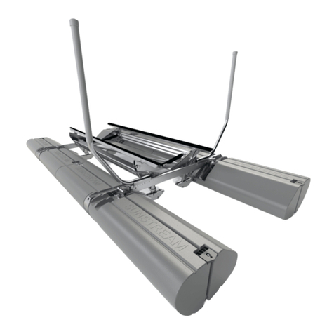
Sunstream BOAT LIFTS FL6012 Setup guide

FORM NO.
PAGE 1 OF 28
REV.
690187
G-01
READ CAREFULLY.
KEEP THESE INSTRUCTIONS.
™
ASSEMBLY, USE AND INSTALLATION MANUAL
FL
6012
COPYRIGHT SUNSTREAM CORPORATION 2006 - ALL RIGHTS RESERVED

Disclaimer of Liability
These assembly and installation instructions have been provided by Sunstream Corporation at
the request of the potential installer and/or assembler. If you are not an authorized Sunstream
Dealer and are not a reasonably skilled mechanic, please contact Sunstream so that we can
refer you to a local dealer who can skillfully and safely perform the assembly and installat
i
on
of your Sunstream boatlift.
It is the potential installer's and/or assembler’s responsibility to determine whether he or she has
the necessary skills, knowledge, and tools to properly and safely assemble and/or install the
Sunstream Lift described herein. Improper assembly and/or installation may cause the lift to
function improperly or not to function. Improper assembly and/or installation may additionally
cause a risk to personal safety or property. If the assembler and/or installer is confused or has
questions or concerns about a particular assembly or installation, he or she should contact
Sunstream by telephone at (888)-786-5438 before proceeding further. The information
contained in these instructions does not constitute a warranty or guarantee of any kind.
An assembler’s and/or installer’s failure to correctly follow these assembly and installation
instructions constitutes a waiver of the assembler and/or installer’s rights against Sunstream
regarding any subsequent damages to property or personal injury caused by the assembler’s
and/or installer’s improper assembly and/or installation
.
Table of Contents
Disclaimer of Liability……………………………………………..………..………………..
Tools Needed/recommended…………………………………………...…………….....
Assembly Instructions for FL6012A-D/FL6012S-D………………………...………….
Zinc Information & Installation…………………………………………………..............
Prior to Launch............................................................................................................
Installation Instructions/Mooring the FloatLift…………………….………………..
Operating Instructions………………………………………………………………...
Important Safety Instructions…………………………………………………....…...
Use and Maintenance Tips (programming remote control)……...………...….....
Battery Tips..................................................................................................................
Troubleshooting Tips...................................................................................................
Warranty…………………………………………………………………………….……….
3
4
4-14
15
16
17-20
21-22
23-24
25
26
27
28
FORM NO.
PAGE 2 OF 28
REV.
690187
G-01


ASSEMBLY, FRAME, FL6012, PREASSEMBLED
941095
1X
1X
AS., LEFT FLOAT, PREASSEMBLED, FL0612
941105
941108
ASSEMBLY, RIGHT FLOAT, PREASSEMBLED, FL6
1X
WITH STRAP
941106
ASSEMBLY, RIGHT FLOAT, PREASSEMBLED, FL6
1X
1X
ASSEMBLY, LEFT FLOAT, PREASSEMBLED, FL6
WITH STRAP
941107
1X
AS., HARDWARE KIT, PREASSEMBLED, FL6012
FORM NO.
PAGE 3 OF 28
REV.
690187
G-01

1
ASSEMBLY
If you have
any questions during the assembly process, please call your local dealer
or Sunstream as (888) 786-5438.
Before beginning assembly, find a flat area with room to work to set up your lift.
Read ahead to the Installation Procedure to determine the best location to start.
Assembly will require the following tools:
1. 9/16 wrenches
2. Marine Grease - (stainless pivot pins)
3. Needle nose pliers - (cotter pins)
4. Hammer
5. Measuring Tape
6. Torque Wrench
Antiseize all bolts/threaded rods.
•
Grease all pins with Marine Grease.
•
FORM NO.
PAGE 4 OF 28
REV.
690187
G-01

NUT, .375-16, NYLOCK, SS
BOLT, .375-16 X 3.00, HEX, SS
2
FORM NO.
PAGE 5 OF 28
REV.
690187
G-01

2X
NUT, .500-13, NYLOCK, SS
50 Ft-lbs
68 N-m
3
FORM NO.
PAGE 6 OF 28
REV.
690187
G-01

WASHER, .750, SS
OUTSIDE
WASHER, .750, PLASTIC
(INSIDE)
PIN, COTTER, .125 X 1.50, SS
PIN, .750 X 4.25, SS, HIGH STRENGTH
PIN HERE
4
FORM NO.
PAGE 7 OF 28
REV.
690187
G-01

WASHER, .750, PLASTIC
WASHER, .750, SS
PIN, COTTER, .125 X 1.50, SS
PIN HERE
PIN, .750 X 4.25, SS, HIGH STRENGTH
5
FORM NO.
PAGE 8 OF 28
REV.
690187
G-01

PIN HERE
WASHER, .750, SS
PIN, COTTER, .125 X 1.50, SS
PIN, .750 X 4.25, SS, HIGH STRENGTH
6
FORM NO.
PAGE 9 OF 28
REV.
690187
G-01

7
8X
FORM NO.
PAGE 10 OF 28
REV.
690187
G-01

8
PAGE INTENTIONALLY
LEFT BLANK
FORM NO.
PAGE 11 OF 28
REV.
690187
G-01

NUT, .375-16, NYLOCK, SS
BOLT, .375-16 X 3.50, HEX, SS
9
FORM NO.
PAGE 12 OF 28
REV.
690187
G-01

BOLT, .375-16 X 3, BUTTON, SS
NUT, .375-16, NYLOCK, SS
10
BOTH
SIDES
FORM NO.
PAGE 13 OF 28
REV.
690187
G-01

RED
GREEN
RED
GREEN
11
FORM NO.
PAGE 14 OF 28
REV.
690187
G-01

TO MINIMIZING GALVANIC CORROSION, IT IS ESSENTIAL THAT SACRIFICIAL ZINCS ARE INSTALLED AND
MAINTAINED ON YOUR LIFT. ZINC IS USED AS IT HAS A HIGHER VOLTAGE IN WATER SO THE CURRENT
WILL BE MORE INCLINDED TO FLOW FROM IT. THE ZINC BECOMES THE CORRODING ANODE, WHILE THE
LIFT SERVES AS THE CATHODE AND IS PROTECTED FROM CORROSION.
IT IS IMPERATIVE THAT YOU REPLACE THE ZINC ON YOUR LIFT REGULARLY.
BECAUSE MANY EXTERNAL FACTORS AFFECT THE RATE AT WHICH A ZINC DETERIORATES, SUNSTREAM
RECOMMENDS THAT YOU CHECK IT'S CONDITION FREQUENTLY, AND CHANGE THE ZINC EVERY SIX
MONTHS OR MORE OFTEN IF NEEDED. ZINCS ON LIFTS IN COASTAL AREAS NEAR THE OCEAN
DETERRIORATE MORE RAPIDLY AND NEED TO BE CHANGED MORE FREQUENTLY.
EFFECTS OF
GALVANIC CORROSION ARE NOT COVERED BY YOUR SUNSTREAM WARRANTY. NOT MAINTAINING
ZINCS ON THE LIFT CONSTITUTES ABUSE AND VOIDS THE SUNSTREAM WARRANTY.
PROTECT YOUR INVESTMENT WITH THE PROPER STEPS.
TO COMPLETE THE ELECTRICAL CIRCUIT, THE
ZINCS MUST BE CONNECTED TO THE LIFT TIGHTLY AS SHOWN BELOW. SUNSTREAM RECOMMENDS
USING HIGH-QUALITY ZINCS THAT ARE AVAILABLE THROUGH SUNSTREAM SERVICE DEPARTMENT.
4X
NUT, .250 - 20, SS
SOCKET HEAD CAP SCREW, 1/4"-20 X 1.125
ZINC, 5.25" LONG, CMT 21, FLOATLIFT
12
FORM NO.
PAGE 15 OF 28
REV.
690187
G-01

FOR FL6012, USE POWER PACK SHELF FA-PS6.
ASSEMBLY INSTRUCTIONS INCLUDED WITH POWERPACK SHELF KIT.
PRIOR TO LAUNCH
CHECK:
ALL COTTER PINS ARE BENT AND SECURE.
1.
ALL NUTS ARE TIGHT.
2.
HYDRAULIC HOSES ARE CLEAR FROMPINCH POINTS.
3.
BATTERY TERMINALS AND QUICK DISCONNECTS ARE TIGHT ARE FULLY
4.
SEATED.
RED RESERVOIR CAP IS REMOVED (UNDER BREATHER CAP).
5.
13
14
FORM NO.
PAGE 16 OF 28
REV.
690187
G-01

INSTALLATION INSTRUCTIONS
If you have any questions, please call your dealer, or Sunstream at (253)-395-0500
Installation instructions and diagrams follow. These instructions and diagrams provide
basic information about how to securely and safely install the FloatLift. Adhering to these
instructions and diagrams, however, provides no guarantee that the installation will be
safe and secure. The FloatLift user must also consider site-specific facts such as wave,
wind, and current action and storm potential in his/her analysis of the installation site and
method.
!
WARNING
•
The Maximum Buoyancy Capacity for the Lift is 6,000 lbs. Total boat weight should not
exceed 5,500 lbs. to allow for a safety margin. Operating the lift with a greater amount
of total weight may cause the lift and boat to become unstable and/or capsize, possibly
causing property damage and/or and severe injury or death to individuals situated nearby.
One important indication of overloading is when the lift’s “MAXIMUM WATERLINE” marking
is submerged.
•
The installer must be aware of the conditions the Lift will/may be subjected to at the
proposed location. Waves and wind may affect stability. Excessive wave action or wind
may require that the boat be secured to the lift, or that the lift be moved to a secure site.
•
Treat your lift like a boat for moorage purposes. Check docklines and other moorage
connections frequently, especially if connections will be subject to stresses such as those
caused by water fluctuation or currents.
•
Ensure that your boat is situated on the lift in a manner that will avoid damage to your
boat or other property. Confirm that no part of the lift except the rubber covered portion
of the bunks contacts your boat. Confirm that your boat or the lift will not strike any nearby
object in the case of wave action. Install fendering or other padding as required.
•
Verify engine intakes are not blocked by the lift.
•
To avoid unwarranted product wear and tear, secure the lift so that the floats or other
parts of the lift do not strike or rub against the dock or other structures and/or adequately
pad points where such contact may occur.
Refer to the safety instructions, maintenance tips, and other sections of this manual for
additional information.
•
Use caution to prevent hydraulic hoses from being pinched or worn.
FORM NO.
PAGE 17 OF 28
REV.
690187
G-01

A.)
Floating Dock with a height less than 3’ above water
and with a Dock Length Greater than Floatlift
FORM NO.
PAGE 18 OF 28
REV.
690187
G-01

B.)
Floating dock with height less than 3’ above water, Single Overhang
C.)
Floating Dock with a height less than 3’above water, Double Overhang
FORM NO.
PAGE 19 OF 28
REV.
690187
G-01

Tide Fluctuations
D.)
Floating dock with a height less than 3’above water, Standard Slip
FORM NO.
PAGE 20 OF 28
REV.
690187
G-01
Table of contents
Other Sunstream Boating Equipment manuals

Sunstream
Sunstream FL-24020D User manual

Sunstream
Sunstream FL10 Instruction manual

Sunstream
Sunstream FL15023 User manual

Sunstream
Sunstream FL6 HOVERCOVER User manual

Sunstream
Sunstream SunLift SLX 5010 User manual

Sunstream
Sunstream FL10 Setup guide

Sunstream
Sunstream FL15023 Specification sheet

Sunstream
Sunstream FL10014 Technical specifications

Sunstream
Sunstream BOAT LIFTS FL13018 Setup guide